FPGA Implementation of Boolean Neural Networks using UML Roman Kohut, Bernd Steinbach, Dominik Fröhlich Freiberg University of Mining and Technology Institute of Computer Science D-09596 Freiberg, Germany email:{kohut, steinb}@informatik.tu-freiberg.de
[email protected]
Abstract This paper suggests a new approach for modeling of Boolean neural networks on fieldprogrammable gate arrays (FPGAs) using UML. The presented Boolean neural networks (BNN) allow a decreasing of the required number of configurable logic blocks (CLB) for the realizing of Boolean neuron. The element of BNN, called Boolean neuron, may be mapped directly to lookup table (LUT) and configurable logic block (CLB) of FPGAs. Our approach solves digital design problems especially with respect of the performance and gate count. In the examples through paper we describe the UML model of the BNN, its transformation, and the mapping to FPGAs.
1 Introduction Field programmable gate arrays (FPGAs) are becoming increasingly popular for prototyping and design of complex hardware systems. The flexibility, capacity, and performance of FPGA devices have opened up completely new direction in high-performance computation, forming the basis of run-time reconfigurable computing (RTR). Run-time reconfigurable computer systems typically combine a classical microprocessor with programmable logic resources, like FPGAs [1]. The structure of a FPGA is an “array of logic blocks” connected together via programmable interconnections. The basic elements of FPGAs are configurable logic blocks (CLB) that typically contains n lookup tables (LUT), an optional D-Flip-Flop (DFF) and additional control logic. In our case 4 LUTs are included into CLB. A LUT is a 4 input logic block that can implement any Boolean function of four variables. Since Boolean neural networks are intended to represent Boolean functions, FPGA-based reconfigurable architectures seems suitable to implement Boolean neural networks completely. However, the FPGA realization of BNN with a large number of neurons is still a challenging task because BNN algorithms require many multiplications and it is relatively expensive to implement multipliers on fine-grained FPGAs. Moreover, FPGAs still implement a limited number of logic gates and interconnections [3,16]. Connectivity problems are not solved even by using reconfigurable FPGAs [6, 7]. For the realization of one usual neuron tens or hundreds of LUTs and CLBs are required [3,9,12]. In order to decrease of CLBs number for modelling of neural networks, we suggested functional changes of the usual neural element and described this new type of neuron in our previous papers [10 12]. The presented Boolean neuron can be implemented directly into a single LUT.
2 Boolean Neural Networks In this paper we do not consider the Boolean neuron and the synthesis methodology of Boolean neural network structure on the base of Boolean neuron because it has been described in our previous papers. We only briefly view structure of Boolean neuron and neural network and explain details of a very promising approach of FPGA implementation of Boolean neural networks using UML models. Both the earlier suggested Boolean neuron and the whole BNN apply Boolean operations to Boolean signals. The output signal of the Boolean neuron is defined as y = fB (xB, wB), where the index
B indicates Boolean values, xB ={x1, x2,…, xNx}, wB ={w1, w2,…, wNx}, fB is a Boolean transfer function and xi, wi, fB, y ∈{0,1}. The change to Boolean values and Boolean transfer function fB reduces time for converting input signal vector into output signal significantly. An additional advantage of the Boolean neuron is reduction of necessary memory size. LUT1
BN1
LUT2 LUT3
BN3
LUT4
BN4 BN5
Interconnections
BN2
LUT5
LUT6
BN6
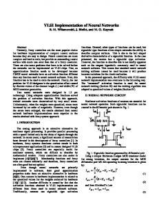
Figure 1. Mapping of BNN to FPGA. The structure of the Boolean neuron with 4 inputs has same logic structure as lookup table. Consequently the limitation of a Boolean neuron to 4-inputs in the Boolean neural network allows a direct representation of BNN to the FPGA structure that can be presented as a network of LUTs (see Figure 1). A result of the training of a BNN is a network of neurons with defined transfer functions and weight coefficients for all neurons on the hidden and output layers. We take a trained BNN and exemplify the transformation of this network to FPGAs. Example 1. The trained BNN represents a set of Boolean functions y0, y1,…, y9. each of them is defined on 3 variables x1, x2 and x3. Let the transfer functions of hidden neurons be Boolean dependences, which are expressed in figure 2a. On the output layer a disjunctions of k-functions are used. The corresponding connections of k-functions are presented through the weight coefficients that are shown in figure 2b. For example the function y1 is a disjunction of the k1 and k2 (grayed). The structure of BNN is shown in figure 2c. By a training of BNN the number of inputs for neurons was restricted to the number of inputs of the LUT of the FPGA [12]. x1
x2
x3
k1
k2
k3
k4
0 0 0 0 1 1 1 1
0 0 1 1 0 0 1 1
0 1 0 1 0 1 0 1
0 1 0 1 0 1 1 0
0 0 0 0 1 0 0 0
1 1 0 0 0 0 0 0
0 0 1 0 0 1 0 1
y0 k1
x1 y1 k2
x2 a)
k3 k1 k2 k3 k4
y0
y1
y2
y3
y4
y5
y6
y7
y8
y9
1
1
0
1
0
1
1
0
0
0
0
1
0
0
1
0
1
1
1
0
0
0
1
1
0
0
1
1
1
0
0
0
1
0
1
1
0
0
1
1
…
x3 y9 k4 b)
c)
Figure 2. a) Transfer functions of hidden neurons of BNN; b) Weight coefficients for output neurons; c) Structure of BNN Obviously the BNN of the example shown in Figure 2 c) can be simplified such that all four Boolean neurons k1, …, k4 are removed. This is possible because each of the output function y0,…, y9 depends on 3 variables only. We take this restricted example for a complete representation by small function tables in Figure 2.
In order to automatically map the trained BNN to circuitry, the MOCCA compiler tool [1, 14] is used. For this we need to describe the network as a UML (Unified Modeling Language) model. Fig. 3 illustrates a respective system-level design of a BNN using UML. Example 2. The Boolean neural network, which was cited in example 1, is presented as UML-model in figure 3. The class Main instantiates a number of Bnn objects, which present the set of the Boolean functions y0, y1,…, y9, whereas -app run_bnn -bnn each function is dependent on the Main Bnn 1 0..* 3 Boolean variables x1, x2 and x3. +a : boolean +create() : Main +b : boolean +destroy() : void Concurrently all Boolean +c : boolean +main() : int functions from initially set can return (!a&&!c || a&&!b&&c || a&&b&&!c); +y00 : boolean +y01 : boolean be built on 4 k-functions that ... boolean[] x=new boolean[Nx]; were found in the training phase. +create() : Bnn boolean[] y=new boolean[Ny]; return k01 || k02; +destroy() : void The class Bnn has for each +k1() : boolean Bnn net = new Bnn(); transfer function of neurons on +k2() : boolean ... k01=k1(); +...() net.init_x(x); the hidden and output layers of k02=k2(); +y0() : boolean if(net.calculate()) { ... a=inputs[0]; +y1() : boolean y=net.get_y(); Boolean neural network a y00=y0(); b=inputs[1]; +...() ... y01=y1(); c=inputs[2]; y[0]=y00; method, which should be +calculate() : boolean } ... y[1]=y01; +init_x( x : boolean[] ) : void destroy net; mapped into one LUT. The y09=y9(); ... +get_y() : boolean[] destroy y; y[9]=y09; ... destroy x; complete BNN will be evaluated return true; return y; return 0; in the FPGA by the single invocation calculate() in Figure 3. Design model the main() method. Though the specification of Boolean neural network is a very straightforward UML model, in result of the intensive optimising on the MOCCA level an optimal hardware mapping of BNN is obtained.
3 Compilation of UML-Models The model in Fig. 3 is independent from the particular implementation. That is, the very same model may be implemented using software, hardware, or a mixture of both. Different implementations will expose different implementation characteristics. Which implementation is chosen is subject to the mapping of the design to the particular hardware platform. For the purpose of this paper we assume that the class Main is being mapped to software while the class Bnn is realized using an FPGA. The translation of UML models to partial software implementations, using C/C++ or Java as implementation language, is state-of-the-art. MOCCA extends this approach by the introducing the notion of UML hardware synthesis [1, 14]. The implementations synthesized by this tool are highly optimized and support object-orientation in both, software and hardware. The tool is adapted to different target implementation platforms by means of a UML model describing the resources and resource services available on the platform. For each resource service this model describes the implementation characteristics, and how to utilize the service in implementations. This approach is called model-driven compilation. Using this information this compiler automatically maps UML designs, such as shown in Fig. 3, to the respective implementation platform. For each implemented model element of the design a suitable implementation on the target platform is used. Since common designs are not directly implementable with logic circuits, MOCCA transforms the designs respectively. For instance, the BNN in Fig. 3 makes use of method invocations. While the transfer of control is rather direct in software implementations, the implementation using logic circuitry is not as straightforward. To overcome this challenge MOCCA inlines the called method of such invocations into the calling method. This has the additional advantage, that both methods can be optimized in conjunction. The mixed control- and dataflow being used in UML models is implemented in hardware as FSMD (finite state machine with attached datapath). The mere implementation of the user logic in circuitry is not sufficient. In order to be useful it must be accessible by system parts that execute on external processing elements. This communication interface generally comprises a bridge and a register file. The bridge adapts the physical communication interface of the FPGA, e.g. PCI-bus, Ethernet, serial line, to a standardized, proprietary bus. The register file stores all input and output data of the user logic, and supports the synchronization between different processing elements. Both, the communication interface and the register file are generated automatically by MOCCA using predefined hardware components that have been described in the platform model.
4. Experiment results The design model of BNN from our permanent example was automatically implemented with the MOCCA compiler using C++ and VHDL-RTL implementations platforms. The overall compilation/synthesis time of the design model into the final hardware/software modules takes approximately 3 to 5 minutes, depending on the degree of optimisation. The Boolean neural network was tested on a hardware platform comprising a Pentium IV processor running at 2.4 GHz and a Xilinx Virtex-II FPGA with approximately 3 million gate equivalents running at 100 MHz. Example 3. The FPGA implementation of the BNN, including the communication interface and register file, of our permanent example requires about 64 slices (see table 1), which corresponds to less 4% of the available area. Additionally 92 Flip Flops are used to store the input and output data, and the FSM states. The resources being required just by the BNNs user logic, that is without the communication interface and register file, are shown in brackets. Table 1. Device Utilization Summary Logic Utilization Number of Slices: Number of Flip Flops: Number of 4 input LUTs: Number of bonded IOBs: Number of GCLKs:
Used for Bnn 64 (49) 92 (79) 91 (56) 102 1
Available 1536 3072 3072 172 16
Utilization 4% 2% 2% 59% 6%
Table 2 shows the utilization of the individual methods of Bnn. It is important to emphasize that the implementation of the datapath of method Bnn::calculate is optimum, since it requires the minimum amount of 4-input LUTs that are necessary to implement its functionality. This is particularly noticeable since the rather sequential, software-oriented design style being used in the UML model does not support optimum implementation directly. The implementation can be attributed to the following optimizations: method inlining, elimination of common sub-expressions, replacement of variables whose value is used only one by the defining expression, operation chaining and multicycling over multiple FSM states, replacement of variables by signals (wire variables), avoiding the implementation of unused methods/attributes. These optimizations are applied to the model until no more improvement is made. Table 2. Detailed Resource Utilization and FSM States Method Bnn::calculate Bnn::create Bnn::destroy Bnn::k1 Bnn::k2 Bnn::k3 Bnn::k4 Bnn::y0 Bnn::y1 Bnn::y2 Bnn::y3 Bnn::y4 Bnn::y5 Bnn::y6 Bnn::y7 Bnn::y8 Bnn::y9
# Slices 18 1 1 4 3 2 3 2 2 2 2 2 2 2 2 2 2
#Flip Flops 27 1 1 5 4 4 5 3 3 3 3 3 3 4 3 4 3
#4-input LUTs 21 0 0 7 5 3 4 2 3 3 3 3 3 3 3 3 2
#FSM States 22 2 2 7 5 4 6 3 3 3 3 3 3 4 3 4 3
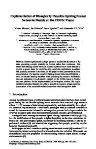
The majority of the resources is consumed by the Bnn::calculate method, which represents the full structure of the BNN after inlining all methods representing k- and y-functions. For its realization 21 LUTs are used. Thereof only 14 LUTs are required for realization of logic structure of the BNN. Other LUTs are used by the controller for the next-state and output logic. The execution time of Bnn::calculate takes 0.200 µs. The methods implementing the k- and y- functions are optionally integrated into the final hardware. Table 2 shows their individual resource utilization and the required FSM states. Although Bnn::calculate integrates all k- and y-functions, whereas the k-functions are inlined multiple times each, the overall utilization is far less than the sum of the utilizations of these functions. This shows the positive effect of the optimizations applied to the fully inlined BNN. The flip-flops are mostly used by the state vector of the FSM, whereas states are one-hot encoded. Example 4. Figure 4 shows the technology schematic for the function k4. In the result of lack of space, it is impossible to show the full circuit of Boolean neural network. The function is realized by 1 LUT_3_98, which Karnaugh Map is presented in 4a. All others circuit elements are part of a sequential control. Only one LUT was required for FPGA implementation of Boolean neuron that means for a representation of the Boolean function with Boolean neural network. a)
b)
Figure 4. a) Karnaugh Map of LUT_3_98; b) Technology schematic of k4()
5 Conclusion and Future Work The Boolean neural networks are used for presentation of Boolean functions. Using proposed Boolean neural networks and Boolean neurons we could decrease the calculation time for both training and using the BNN. It reduces also the necessary memory size significantly. As shown in [11] the Boolean neural networks allow a determining a special decomposition of Boolean functions sets into a small number of unique basic functions. The training of a BNN solves the very difficult decomposition task for a set of Boolean functions [11]. The representation of Boolean function sets by Boolean neural networks extends the possible approaches in circuit design significantly. FPGA-based reconfigurable architectures are well appropriated to implement Boolean neural networks. Moreover, the using of Boolean neurons in the structure of BNN makes possible an optimal implementation of BNN on FPGAs. Only one LUT is required for the hardware implementation of a 4-input Boolean neuron. The complete logic of a Boolean neuron is mapped directly into a lookup tables. A single slice can realize a 5 input Boolean neuron, a CLB – a 6 input Boolean neuron or even 4 Boolean neurons with 4 inputs. This is huge win compared to existing FPGAs implementation of the classical neural networks [3, 8, 9, 16].
In the future, we continue our research for optimal FPGA implementation of Boolean neural networks and the automated hardware/software synthesis with MOCCA and UML. A design and develop a mapping methodology for Boolean neural networks with on-chip learning should be also very interesting task.
References [1] Beierlein, T; Fröhlich, D.; Steinbach, B.: UML-Based Co-Design for Run-Time Reconfigurable Architectures. in: Proceedings of the FORUM on Specification and Design Languages, September 23 - 26, 2003, Frankfurt, Germany, pp 285 - 296. [2] Blake J.J., Maguire L.P., Mc Ginnity T.M., Roche B., and Mc Daid L.J., "The Implementation of Fuzzy Systems, Neural Networks and Fuzzy Neural Networks using FPGAs", Information Sciences: An International Journal, Elsevier, 112 (1998), pp151-168. [3] Charles E.Cox and W.Ekkehard Blanz, GANGLION – a fast field-programmable gate array implementation of a connectionist classifier. IEEE Journal of Solid-State Circuits, 27(3):288-299, March 1992. [4] Cloutier J., Cosatto E., Pigeon S., Boyer F. and Simard P.: VIP:an FPGA-based processor for image processing and neural networks. In Proc. MicroNeuro, pp. 330-336, 1996. [5] Compton K. and Hauck S.: An Introduction to Reconfigurable Computing, Invited Paper, IEEE Computer, April, 2000 [6] Eldredge J. G. and Hutchings B. L.: RRANN: a hardware implementation of the backpropagation algorithm using reconfigurable FPGAs. Proceeding of the IEEE World Conference on Computational Intelligence, 1994. [7] Girau B. and LORIA, Dependencies of composite connections in Field Programmable Neural Arrays, NeuroCOLT2 Technical Report Series NC-TR-99-001, June, 1999 [8] Gschwind M., Salapura V. and Maischberger O.: A Generic Building Block for Hopfield Neural Networks with On-Chip Learning. IEEE International Symposium on Circuits and Systems, Atlanta, GA, May 1996. [9] Gschwind M., Salapura V. and Maischberger O.: Space efficien neural net implementation. Proc. of the Second International ACM/SIGDA workshop on Field-Programmable Gate Arrays, Berkeley, CA, February 1994.ACM. [10] Kohut, R.; Steinbach, B.: Decomposition of Boolean Function Sets for Boolean Neural Networks. Proceedings of the 5th International Workshops on Boolean Problems, 23. - 24. September 2004, Freiberg, 2004, pp. 191 – 206. [11] Kohut, R.; Steinbach, B.: Boolean Neural Networks. Transactions on Systems, Issue 2, Volume 3, April 2004, pp. 420 – 425. [12] Kohut, R.; Steinbach, B.: The Structure of Boolean Neuron for the Optimal Mapping to FPGAs. Proceedings of the VIII-th International Conference CADSM 2005. Lviv – Polyana, Ukraine, 2005, pp. 469 – 473. [13] Salapura V., Gschwind M. and Maischberger O.: A Fast FPGA Implementation of a General Purpose Neuron. Lecture Notes in Computer Science 849, Springer Verlag, Berlin, 1994. [14] Steinbach, B., Fröhlich, D., Beierlein, T.: Hardware/Software Codesign of Reconfigurable Architectures Using UML. in: Grant, M.; Müller, W.: UML for SOC Design, Springer, Dordrecht, Printed in The Netherlands, 2005, pp. 89 – 117. [15] Xilinx. The Programmable Logic Data Book. Xilinx, Inc., San Jose, CA, 1993. [16] Zhu J. and Sutton P.: FPGA Implementations of Neural Networks – a Survey of a Decade of Progress. In Proceedings of 13th International Conference on Field Programmable Logic and Applications (FPL 2003), Lisbon, Sep 2003.