Proceedings of the 6th WSEAS International Conference on Microelectronics, Nanoelectronics, Optoelectronics, Istanbul, Turkey, May 27-29, 2007
A Simple Realization of Negative Type Differential Difference Current Conveyor (DDCC) MUHAMMED A. IBRAHIM Department of Electrical Engineering, College of Engineering University of Salahaddin Kerkuk Street, Erbil IRAQ
[email protected] Abstract: - A simple topology for the realization of negative type differential difference current conveyor (DDCC-) is presented. The proposed topology is based on floating output transconductor (FOT) circuits. A CMOS realization of this type current conveyor, which is made up from floating current sources (FCS), is given. Design details and simulation results using PSPICE are given to verify predictions. Key-Words: - DDCC, Current Conveyor, FOT, CMOS, FCS.
1 Introduction
2 Proposed Circuit
Many new types of current conveyors have been presented since the first introduction in 1968 (CCI) [1]. They have been the second-, the thirdgeneration current conveyors (CCII, CCIII) [2,3] and the inverting second-generation current conveyor (ICCII) [4]. These building blocks have found applications in many fields. The most successful type is CCII. Although the CCII can be used to implement many high performance analog circuits, it has an apparent disadvantage of having only one high input voltage (the Y terminal). This disadvantage becomes evident when the CCII is required to handle differential signals, as in the case of an instrumentation amplifier. Moreover, in continuous-time analog signal processing, conventional CCII cannot be used in applications demanding differential or floating inputs like impedance converter circuits. Then the design of such an amplifier requires two or more CCIIs. This problem has been solved with the help of special current conveyors, named differential difference current conveyor (DDCC) and differential voltage current conveyor (DVCC) [5,6]. In this paper, a simple topology based on floating output transconductor (FOT) blocks and a CMOS realization of the negative differential difference current conveyor (DDCC-) based on floating current sources (FCSs) [7] are presented. Unlike the previous CMOS structures of the DDCC and DVCC [5,6], in the proposed circuit the negative output current is produced directly, i.e., without using inverting current mirror stages.
The proposed circuit implementation of the DDCCis based on the block diagram shown in Fig. 1. Blocks gm1 and gm2 form the input stage, while the output stage is formed by block gm3. All of the three blocks are FOT stages. Since the input current of the third FOT is zero the output currents of the first and the second FOT must be equal, i.e., I o1 = − I o 2 → (VY 3 − VY 2 ) gm1 = −(VY 1 − V X ) gm2
(1)
The gain between Y and X terminals depends on the transconductances gm1 and gm2 which must be equal in order to have the voltage property of DDCC which is V X = VY 1 − VY 2 + VY 3
(2)
A negative feedback is used in order to minimize the input impedance at the X terminal. It is worth noting that the negative type of the current conveyor isn’t adapted from the positive type one as in [5,6]. In contrast, the DDCC+ can be adapted from the DDCC- by adding another FOT as shown in the block diagram of Fig. 2. Many DDCC- realizations with different performance can be obtained according to the basic FOT circuit used. Fig. 3 shows the proposed DDCC- CMOS realization based on two balanced output currents structure named floating current source (FCS) [7] which requires no transistor matching constraint unlike the current mirrors structure. Essentially, this structure is just two matched CMOS inverters biased by two current sources and operates as an analogue transconductor stage. The transistors of the output stage provide two balanced output currents; one of
59
Proceedings of the 6th WSEAS International Conference on Microelectronics, Nanoelectronics, Optoelectronics, Istanbul, Turkey, May 27-29, 2007
them is fed back into the X terminal and the other is the Z terminal. The advantages of the proposed structure are that it is simple since it is made up from three stages of same type building block (FCS) and it does not contain any current mirror circuits, i.e., there is no accuracy problem in current transferring. The accuracy between IX and IZ is determined by the matching of the transistors that provide the biasing currents.
VY3
+ gm1
VY2
-
I o1
+ -
+ gm3 VY1
+ gm2
VX
-
+ -
Iz
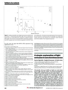
3 Simulation Results The proposed DDCC- realization has been simulated using PSPICE with model parameters of 0.5µm MIETEC CMOS process. The supply voltages used have been selected as ±2.5V for all stages, while the biasing currents have been chosen as 20µA for the input stages and 200µA for the output stage. The aspect ratios of the CMOS realization are given in Table 1. The simulated DC characteristics between the Y and X terminals voltages (VX=f(VY1,VY2,VY3)) is shown in Fig. 4. The simulated DC transfer characteristic between the currents IX and IZ is shown in Fig. 5. The X terminal input resistance and the Z terminal output resistance are approximately 16Ω and 2.8MΩ, respectively. A detailed simulation results are tabulated in Table 2.
I o2
+ -
VDD VC1
Fig. 1:The block diagram of DDCC- implementation
MB1
M1
M2
M3
M4
VY3
VY2
+
VY2
-
gm1
+ -
VC1
MB2
VC2
VY3
VDD MB5
M9
VSS
+ gm3 -
+ -
VDD
I z2
VC1
M11
VY1
gm4
+ gm2
VX
-
+ -
-
+ -
I z1
M12
MB3 VC2
+
M10 Z
M5
M6
M7
M8
VY1
MB6 VSS
VX
VC2
MB4 VSS
Fig. 2:The block diagram of DDCC+ implementation
Fig. 3: Proposed CMOS implementation of DDCC-
Fig. 4: VX=f(VY1,VY2,VY3) characteristic of the proposed CMOS DDCC-
60
Proceedings of the 6th WSEAS International Conference on Microelectronics, Nanoelectronics, Optoelectronics, Istanbul, Turkey, May 27-29, 2007
Fig. 5: DC characteristics between the currents IX and IZ of the proposed CMOS DDCCwide bandwidths both in voltage and current operations.
4 Conclusion A simple topology for the realization of negative type differential difference current conveyor is presented. The implementation of the current conveyor is based on floating output transconductor stages. The proposed CMOS structure of the negative type of the current conveyor (DDCC-) is realized using FCS circuits without using current mirrors. PSPICE simulation results with small transistor sizes have been carried out showing the high performance of the proposed circuit in terms of high linearity, good input and output resistances and
Table 1: Transistor dimensions of the proposed CMOS DDCC- circuit TRANSISTOR W (µm) L (µm) M1,M2,M5, M6 2.5 2 M3,M4,M7,M8 1.2 2 M9,M10 8 0.5 M11,M12 3 0.5
Table 2: Simulation results for the proposed DDCCParameter
Simulation result
DC offset voltage
30µV
DC voltage swing
±1.25V
DC current swing for 150µA biasing
±130µA
X-terminal parasitic input resistance (rx)
16Ω
Z-terminal output resistance
2.8MΩ
Voltage follower stage band width
161MHz
Current follower stage band width
201MHz
THD for 1MHz and 1VP-P (voltage follower stage)
0.05%
THD for 1MHz and 260 µAP-P (current follower stage)
0.45%
Total DC power dissipation
2.2mW
61
Proceedings of the 6th WSEAS International Conference on Microelectronics, Nanoelectronics, Optoelectronics, Istanbul, Turkey, May 27-29, 2007
References: [1] SEDRA, A., and SMITH, K.C.: “The current conveyor: A new circuit building block”, Proc. IEEE, Vol. 56, 1968, pp. 1368-1369. [2] SEDRA, A.S., and SMITH, K.C.: “A second generation current conveyor and its application”, IEEE Trans., CT-17, 1970, pp. 132-134. [3] FABRE, A.: “Third-generation current conveyor: A new helpful active element”, Elec. Letters, Vol. 31, 1995,pp. 338-339. [4] AWAD, I.A. and SOLIMAN, A.M.: “Inverting second generation current conveyors: the missing building blocks, CMOS realizations and applications”, Int.J.Electronics, Vol. 86, 1999, pp. 413-432.
[5] CHIU, W., LIU, S.I, TSAO, H.-W and CHEN, J.-J.: “CMOS differential difference current conveyors and their applications”, IEE Proc.Circuit Devices Syst., Vol. 143, 1996, pp.91-96. [6] ELWAN, H.O. and SOLIMAN, A.M.: “Novel CMOS differential voltage current conveyor and its applications”, IEE Proc.-Circuits Devices Syst., Vol. 144, 1997, pp. 195-200. [7] ARBEL, A. F. and GOLDMINZ, L.: “Output stage for current-mode feedback amplifiers, theory and applications”, Analog Integrated Circuits and Signal Processing, Vol. 2, 1992, pp. 243-255.
62