computing application designer. Indeed, physical mobility is an environment feature that is generally out of the control of the designer; in other words, it is.
A UML Profile to Model Mobile Systems Vincenzo Grassi, Raffaela Mirandola, Antonino Sabetta Universit` a di Roma “Tor Vergata”, Italy
Abstract. The introduction of adaptation features in the design of applications that operate in a mobile computing environment has been suggested as a viable solution to cope with the high heterogeneity and variability of this environment. Mobile code paradigms can be used to this purpose, since they allow to dynamically modify the load of the hosting nodes and the internode traffic, to adapt to the resources available in the nodes and to the condition of the (often wireless) network link. In this paper we propose a UML profile to deal with all the relevant issues of a mobile system, concerning the mobility of both physical (e.g. computing nodes) and logical (e.g. software components) entities. The profile is defined as a lightweight customization of the UML 2.0 metamodel, so remaining fully compliant with it. In the definition of this profile, the underlying idea has been to model mobility (in both physical and logical sense) as a feature that can be “plugged” into a pre-existing architecture, to ease the modelling of both different physical mobility scenarios, and of different adaptation strategies based on code mobility. Besides defining the profile, we give some examples of use of its features.
Keywords: mobile computing, code mobility, UML profile.
1
Introduction
Mobile computing applications have generally to cope with a highly heterogeneous environment, characterized by a large variance in both the computing capacity of the hosting nodes (that span portable devices and powerful fixed hosts) and in the available communication bandwidth, that can range from tens of Kbps to tens of Mbps, depending on the type of wireless or wired network [12]. Moreover, these environment conditions can also rapidly change because of the physical mobility, that can cause a mobile node to connect to different nodes, or to enter zones covered by different wireless networks, or not covered at all. As a consequence, mobile computing applications should be designed so that they are able to adapt to their execution environment, to successfully cope with the problems caused by its high heterogeneity and variability. In this respect, mobile code paradigms and technologies can be exploited to devise possible adaptation strategies [7], for instance by dynamically modifying the current deployment of the application components, to better exploit the new communication and computing features that have become available.
The main goal of this paper is to provide a modeling framework for mobile computing applications, where both the physical mobility of the computing nodes and the logical mobility of software elements are taken into account, since both kinds of mobility deserve consideration, for the reasons explained above. However we would like to remark that, even though our focus is on mobile computing where both physical and logical mobility are present, logical mobility is a valuable design paradigm also in other fields (e.g. wide area distributed applications [7]). To enhance the usability of our framework, we have defined it as a UML 2.0 lightweight extension, exploiting the Profile mechanisms, so remaining fully compliant with the UML 2.0 metamodel [3]. For what concerns the modeling of the physical and logical mobility, we would like to point out that they play different roles from the viewpoint of a mobile computing application designer. Indeed, physical mobility is an environment feature that is generally out of the control of the designer; in other words, it is a sort of constraint he has to deal with, to meet the application requirements. On the other hand, logical mobility is really a tool in his hands, that he can exploit to better adapt the application to the environment where it will be deployed. Despite this basic difference, we have adopted a common approach in modeling them, based on a clear separation of concerns between, on one hand, the models of the application logic and of the platform where the application will be eventually deployed and, on the other hand, the models of the logical and physical mobility. The underlying motivation has been to look at mobility (both physical and logical) as a feature that can be “plugged” into the system model, to support, for example, “what if” experiments concerning a mobile computing environment: for a given application logic and deployment environment (with possible physical mobility), what happens if different mobile code based adaptation strategies are plugged into the application? what if the physical mobility does change? Note that, of course, “what happens” should be defined in terms of some observable application property (e.g. some performance measure). In this respect, we would like to remark that we have adopted a minimal approach in our modeling framework, including in it only aspects strictly related to mobility. We do not have included in it the modeling of other aspects that could be relevant in a given analysis domain (for example, resource features and utilization to be used for performance analysis). Depending on the type of analysis one is interested in, our modeling framework should be integrated with other modeling frameworks (e.g. the UML “Profile for Schedulability, Performance and Time Specification” in the case of performance analysis [2]). The representation of mobility in computer systems has been treated in a number of work in the past. Some of them tackled this issue using UML based approaches [9, 4], while others have adopted more formal and rigorously defined frameworks [10, 11, 6, 5]. For what concerns the former approaches, the proposal in [9] requires a nonstandard extension of UML sequence diagrams; on the other hand the proposal in [4] extends the UML class and activity diagrams allowing the representation of mobile objects and locations as well as basic primitives such as moving or cloning.
In this work both the mobility model (how objects move) and the computational model (which kind of computation they perform) are represented within the same activity diagram. For what concerns the latter approaches, they in general provide useful insights for mobility related modeling problems, but the non widespread diffusion of the formal notations they are based on limits their direct use in real modeling problems. The paper is organized as follows: in the next section we start identifying the key aspects that deserve to be modeled in mobile systems, introducing some conceptual schemata and a reference framework. In section 3 we define the profile modeling elements while in section 4 we give some examples to show how the profile and the conceptual guidelines sketched in section 2 can be used. Moreover in section 5 we use the profile to model some basic mobile code paradigms. Finally, in section 6 we draw some conclusions and outline a few interesting issues that could be the subject for further investigation and future works.
2
Modeling Mobile Systems
We are interested in devising a framework that gives the application designer the possibility of extending a basic model of a computer (software) system by adding or removing mobility at will, in order to experiment with different environment characteristics and design solutions since the earliest phases of the design process. In order to do so, we have to clearly define the following issues: – how to model the movement of an entity; – which entities move; – what causes the movement of an entity. Note that the above issues apply to both physical and logical mobility; hence, as far as possible, we will adopt a common approach to model them. For what concerns the first issue, we believe that any attempt to represent movements requires that an underlying concept of location be defined. In our framework we model this concept as a relationship that binds two entities so that one acts as a container for the other, thus we will say that the latter is located in the former. We have derived from [5] the basic idea of modeling locations as nesting relationships among entities. However, with respect to the simple (and elegant) unifying model of [5], we have implemented in two different ways this idea for physical and logical mobility as shown in section 3, to remain compliant with the UML metamodel, trading off simplicity and elegance with usability. Given this basic model of location, a movement is modeled as a change in the relationship between a mobile entity and its container. With regard to the second issue, both logical and physical mobile entities must be considered. A logical mobile entity can be, in principle, any kind of software artifact (run time entity), intended as the manifestation of a software component (design time entity) whose location can be an execution environment or a computing node.
On the other hand, the physical mobile entities can be computing nodes (and the execution environments inside them) whose location is a place (such as a building, a room or a vehicle). Places themselves can be mobile and can be located in other places (e.g. a car, which can be considered as a place on its own right, can be located inside a building) so that possibly complex hierarchical topologies can be conceived. Any movement, either of a physical or a logical entity, should be constrained by a simple principle: it can happen only if the location where the moving entity currently is and the destination location are connected by a channel. Since this concept is so generic and abstract, the idea of a channel can be easily mapped, in a very intuitive way, onto different types of mobility. For instance a network link between two workstations can be described as a channel interconnecting two execution environments so that, under certain conditions, the software components located in one of the two workstations can flow across the channel and migrate towards the other workstation thus realizing software mobility. Similarly a corridor between two rooms can be thought of as a channel that allows a mobile device, such as a PDA (i.e. an execution environment) to move from one room to the other. It is important to observe that in this latter example the mobility of an execution environment, which is rendered explicitly, implies that all the software elements contained by the migrating entity move together with it. Up to now, we have discussed issues concerning the phenomenology of mobility (how we can model the manifestation of a mobile behavior), but we have not tackled the description of what causes and triggers mobility. Our idea is to model this latter issue by means of the mobility manager concept whose main purpose is to encapsulate all the logic of mobility, separating it from the application logic. A mobility manager is characterized by the ability to perceive changes in its “environment” (which can be composed of both physical and software elements) and reacts to them by firing mobility activities, whose effect is to cause a movement (location change) of some mobile entity. We adopt this same concept for both physical and logical mobility. Note that, in principle, a mobility manager should be mainly intended as a modeling facility, that could not directly correspond to some specific entity in a real implementation of the system we are modeling, or whose responsibilities may be shared by several different entities; its modeling utility actually consists in providing an easily identifiable entity where we encapsulate the logic that drives mobility. This separation of concerns implies that different mobility managers, each modeling a different mobility policy, can be modularly plugged into some physical environment or software application model so that different environment dynamics and/or adaptation policies can be experimented. The fundamental difference between mobility managers modeling physical and logical mobility is that the former are models of some existing physically observable behavior which is not modifiable by the software designer, whereas the latter are meant to model behaviors which are completely under the control of the designer, and that can be devised to realize some mobility based adaptation strategy.
3
The Profile
After the domain oriented survey of architectural and mobile code concepts provided in the previous section, we turn now to the very UML viewpoint focusing on the mapping of those concepts onto the UML metamodel. Here we define the semantics of the proposed extensions that build up the profile. 3.1
Place
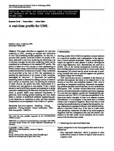
Semantics and rationale. The Place stereotype extends the metaclass Node and represents both the concept of location as delimited by concrete or administrative boundaries and the physical entities located in it (see figure 1). Examples of places are computing nodes, buildings, vehicles, rooms, persons and so on. Places can be nested (e.g. a building can contain rooms, which in turn can contain PCs).
Class
(from StructuredClasses...)
+nestedNode
Node
Place
*
1 +location {subsets nestedNode} +nestedNode
Device ExecutionEnvironment
Dependancy
Association DeploymentTarget +location
Node
+location
*
Deployment
NodeLocation
+nestedNode
Place
AllowedDeployment
CurrentDeployment
Fig. 1. UML metamodel fragment and some of the stereotypes introduced with the profile
3.2
NodeLocation
Semantics and rationale. This stereotype is applied to associations that are defined between Nodes and Places, and it is used to express the location of Nodes (see figure 1). The Place that is attached to the location end of a NodeLocation association represents the location of the Node at the opposite end (nestedNode). The profile supports the specification of activities that modify the value of the location of a given Node (see MoveActivity below).
3.3
MobileElement
Semantics and rationale. This stereotype is used to mark an element as mobile. In particular a Place can be a MobileElement. The location of MobileElements can be changed by means of MoveActivities. 3.4
MobileCode
Semantics and rationale. This stereotype is a specialization of MobileElement. It can be applied to components, classifiers, artifacts or other software level elements to specify that they can be treated as a piece of mobile code and as such can be copied and/or moved and possibly executed in different execution environments. 3.5
CurrentDeployment
Semantics and rationale. This stereotype extends the semantics of the Deployment metaclass and specifies the deployment target where an artifact is currently deployed to. The profile supports the specification of activities that modify the value of the CurrentDeployment of a given entity (see MoveActivity below). 3.6
AllowedDeployment
Semantics and rationale. This stereotype extends the semantics of the Deployment metaclass and specifies which deployment targets are allowed for a MobileCode element. Such multiple specification is used to declare which locations a mobile component can be deployed to. This stereotype can be used to introduce additional constraints on the mobility of a mobile software artifact, to reflect, for example, administrative or security related policies, besides those defined by the physical existence of channels between the execution environments that are the origin and the destination of a movement. 3.7
MobilityManager
Semantics and rationale. The stereotype MobilityManager can be applied to state machines which are meant to control physical or logical mobility. The initial state of the state machine is entered as soon as the system is started. Transitions are labeled with a guard condition (in square brackets) and with the name of an event (e.g. the execution of an activity). A transition is fired when the event specified by the label occurs, provided that the guard condition is satisfied. An activity that operates on one or more MobileElements can be associated to each state or transition of a mobility manager. Such an activity can be defined, in general, as a suitable composition of the activities listed below (3.8 - 3.13).
3.8
MoveActivity
Semantics and rationale. The MoveActivity stereotype can be applied to activities whose execution results in a migration (i.e. change of location) of a MobileElement. Typically a MoveActivity receives in input the MobileElement and its destination location; when the activity is performed, the MobileElement is located in the specified location. The concept of “being located” is represented differently for logical entities (i.e. Artifacts that manifest a software component or a class) and physical entities (i.e. hardware nodes or physical ambients), so the low level effect of the application of a MoveActivity is different according to the type of MobileElement it is invoked for (we call such element the subject of the migration). For physical mobile elements (i.e. Nodes) this is done by changing the association (stereotyped as NodeLocation) with their container Place, whereas for logical elements it is realized updating the CurrentDeployment dependency. Constraints 1. Only MobileElements can be the subject of a MoveActivity 2. If the subject is a MobileCode element, the destination must be an allowed ExecutionEnvironment for it, i.e. an AllowedDeployment dependency must exist between the logical (mobile) element and the destination location. 3. A MoveActivity cannot act on MobileElements if a proper CommunicationPath (what is called a “channel” in section 2) does not connect the starting and the destination locations. 3.9
BeforeMoveActivity
Semantics and rationale. The stereotype BeforeMoveActivity is used to define activities that are performed in order to prepare a MobileCode element to be copied or moved. Examples of BeforeMoveActivites are the serialization of a component in a form that is suitable for transfer, the handling of bindings to resources or local data, encryption of confidential data that must cross untrusted channels and other preliminary tasks. 3.10
AfterMoveActivity
Semantics and rationale. This stereotype is used for activities that operate on a MobileCode element right after its migration to a new execution environment. An AfterMoveActivity must follow a MoveActivity. Examples of operations that are good candidates to be stereotyped as AfterMoveActivities are those related to regenerate out of a serialized transferrable form a component that is capable to be run again. Other tasks that can be classified as AfterMoveActivities encompass handling of bindings to resources needed for proper operation of the migrated component in its new execution environment, recreating data structures and execution context that the component expects to find upon resuming, and so on.
3.11
AbortMoveActivity
Semantics and rationale. The stereotype AbortMoveActivity is used to specify an activity whose execution aborts a migration that was formerly prepared by the invocation of a BeforeMoveActivity. 3.12
AllowDeploymentActivity
Semantics and rationale. An AllowDeploymentActivity is a CreateLinkActivity that adds a deployment to the set of allowed deployments for a given DeployedArtifact. 3.13
DenyDeploymentActivity
Semantics and rationale. This stereotype is complementary to AllowDeploymentActivity and can be used to mark activities that remove a deployment from the set of allowed deployments for a given DeployedArtifact (which means that any former AllowedDeployment of the same Artifact to the specified target is removed).
4
The Profile in Practice: Some Examples
In the following we give some simple examples to clarify the practical aspects of using the proposed profile, showing how to realize models of both structural and behavioral aspects of systems characterized by different forms of mobility. Anyway we remark that, since the profile is not supposed to force practitioners to follow a particular modeling methodology, these examples are only meant to give a few hints, not normative prescriptions.
Home
Office
Server
PDA
Comp_A
ServLoc
Comp_B
Comp_C
Fig. 2. Static system model
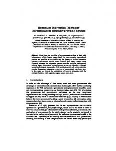
In the provided examples we refer to a basic system model depicted in figure 2; this model represents a “static” system where components deployment and nodes location are fixed. Then, we separately show how to use the profile to plug physical and logical mobility into this static model. 4.1
Modeling Physical Mobility
First of all we introduce in the basic example the provision for physical mobility. Dynamic topological models can be valuable in studying the software application behavior when the physical environment, e.g. the placement of locations and consequently the connectivity conditions, are subject to change. If we want to allow the representation of physical mobility we need to enable hosts themselves and places to be contained in other places in a dynamically changing hierarchical structure composed of elements that are possibly nested and where the hosts are considered as contained entities themselves and not only as containers for software entities.
Home
Office
ServLoc
t> >
Server
PDA
PDA_MM move(PDA,Office)
state A
sleep(uniform(6hours))
state B sleep(uniform(4hours))
Comp_A
Comp_B
Comp_C
(a) Mobile system structure
move(PDA,Home)
(b) Physical mobility manager
Fig. 3. Mobile system model
For the example of figure 2, figure 3 shows how we can plug into it physical mobility. Note that figure 3 also shows profile elements related to logical mobility, but we ignore them in this section. As we can see, the PDA execution environment has been stereotyped as a MobileElement; since a link (modeling the channel concept of section 2) connects the Home and Office places, the PDA is enabled to move between them. Its actual mobility pattern is modeled by the mobility manager PDA MM depicted in figure 3-b.
Note that, with respect to figure 2, figure 3 actually depicts a snapshot of one of the numerous allowed configurations. In the case of physical entities the only constraints to such configurations are enforced by the links that connect the nodes. 4.2
Modeling Code Mobility
As defined in the profile, the formal specification of a mobility manager modeling logical mobility does not basically differ from the definition of a mobility manager modeling physical mobility: also in this case, it consists of a state machine, whose state transitions are triggered by the occurrence of events, possibly conditioned by some guard condition. In the case of logical mobility, typical events triggering a transition are “internal” events of the software application (e.g. sending a message, completing an activity) or “external” events such as a modification of the application execution environment (e.g. a physical movement of a mobile host that causes a change in the available communication bandwidth).
[loc(PDA)==Home] Event1 /
state A
state B entry/SomeMobilityActivity()
[some_condition] Event2 / [loc(PDA)==Office] Event2 /
state D entry/SomeMobilityActivity()
state C entry/SomeMobilityActivity()
[batterylevel(PDA)