past, worst-case design techniques were used to circumvent this problem. .... is correct and thus represents the weight of this particular vote. The variable node ...
A Reliability-Aware LDPC Code Decoding Algorithm Matthias Alles, Torben Brack, Norbert Wehn Microelectronic Systems Design Research Group University of Kaiserslautern 67663 Kaiserslautern, Germany Email: {alles, brack, wehn}@eit.uni-kl.de
Abstract— With the continuing downscaling of microelectronic technology, chip reliability becomes a great threat to the design of future complex microelectronic systems. Hence increasing the robustness of chip implementations in terms of tolerating errors becomes mandatory. In this paper we present reliability-aware extensions of the LDPC decoding algorithm. We exploit application specific fault tolerance of the decoding algorithm combined with modifications on the algorithmic level to increase the reliability of a decoder implementation. These modifications lead to a LDPC decoder implementation which tolerates sporadic errors that occur in critical components. To the best of our knowledge this is the first investigation of the LDPC decoding algorithm in terms of implementation reliability.
I. I NTRODUCTION With further downscaling of CMOS technology, variability in transistor and circuit performance continues to increase. Process variations induced by, e.g., random dopant fluctuations and time-dependant dynamic variations in voltage, temperature, power density, crosstalk and soft-errors make microelectronic circuits and systems less and less reliable. In the past, worst-case design techniques were used to circumvent this problem. At design time the chip was dimensioned in a way that it works correctly for all variations under worst case scenarios. However this approach has the drawback of oversizing the implementation for the typical case (the worst case scenario typically occurs infrequently) which costs area, energy and performance. In addition all worst case scenarios and parameter variations have to be known at design time. Furthermore, the market continues to demand higher reliability levels. As a result reliability becomes a great threat to the design of complex digital systems-on-chips. Hence it is imperative to consider reliability as a cross-cutting problem concerning not only technology and test engineers but also system designers [1] [2]. Moreover market needs require more and more low power/energy systems. Voltage scaling is the most efficient technique to reduce the energy. In conventional practice, voltage scaling is lower bounded. Decreasing the voltage below this bound (voltage overscaling) further decreases the energy, but induces timing errors and, thus, further degrades the reliability of the circuit. Obviously, energy can be traded off versus reliability. In the literature, it has been shown that voltage
overscaling is very efficient as long as appropriate techniques are provided to increase the reliability. For example, Shanbhag [3] proposed a design methodology called arithmetic noisetolerance to enable the use of voltage overscaling. The basic idea is to use a simple error control block by exploiting special signal processing properties of the application, i.e. provide system-level tolerance to counterbalance the errors induced by voltage overscaling [4][5]. In [6] a similar technique was applied to reduce the energy in Turbo-Code decoders by voltage overscaling. A worst case design technique is applied, but the area overhead is reduced by focusing only on the important signals in the decoder. These signals are identified using system knowledge. An important-aware clock skew scheduling technique is presented that assigns at design time circuit paths associated with important bits a longer timing slack. This makes the important signals more robust with respect to timing errors. Some small degradation of the communications performance results due to the focus on important signals only. Nevertheless, all worst case scenarios have to be known at design time what becomes impossible in the future due to the aforementioned dynamic variations which are induced by the process technology, the environment and the operation modes. In this paper we present reliability-aware extensions to the LDPC decoding algorithm. LDPC codes show like TurboCodes an outstanding communications performance and are part, e.g., of the WiFi [7], WiMAX [8], and DVB-S2 [9] standards. We exploit application specific fault tolerance of the decoding algorithm combined with modifications on the algorithmic level to increase the reliability of a decoder implementation. The paper is structured as follows. In Section II we introduce LDPC codes and the corresponding decoding algorithms. Section III addresses the problems of LDPC decoder implementations. In Section IV we present our approach to increase the reliability of the decoding algorithm. Concrete results are given in Section V. Finally Section VI concludes the paper. II. LDPC C ODES LDPC codes are linear block codes defined by a sparse binary matrix H, called the parity check matrix. The set of
valid codewords C satisfies HxT = 0,
∀x ∈ C.
(1)
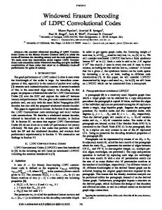
A column in H is associated to a codeword bit, and each row corresponds to a parity check. A nonzero element in a row means that the corresponding bit contributes to this parity check. The complete code can best be described by a Tanner graph, a graphical representation of the associations between code bits and parity checks. Codeword bits are shown as so called variable nodes (VN) drawn as circles, parity checks as check nodes (CN) represented by squares, with the edges connecting them according to the parity check matrix. Figure 1 shows a Tanner graph for a generic irregular LDPC code with N variable and M check nodes with a resulting code rate of R = (N − M )/N . The number of edges connected to a node is called the node degree. If the node degree is constant for all check nodes and variable nodes, the corresponding LDPC code is called regular, otherwise it is called irregular. Note that the communications performance of irregular LDPC codes is known to be generally superior to which of regular LDPC codes. The degree distribution of the variable nodes f[dmax ,...,3,2] gives the v the fraction of variable nodes with a certain degree, with dmax v maximum variable node degree. The degree distribution of the max check nodes can be expressed as g[dmax the ,dmax −1] with dc c c maximum check node degree, meaning that only check nodes with two different degrees occur [10]. A. Decoding Algorithm LDPC codes can be decoded using the message passing algorithm [11]. Iteratively messages between both kind of nodes in the Tanner graph are exchanged, for a hard decision decoder they consist of one bit only. Soft decision algorithms use several bits to represent the received symbols and the messages. This yields a much better decoding performance. The additional bits correspond to the belief whether a made decision is correct or not. We will show later on that this algorithm has some inherent fault tolerance which can be efficiently exploited. Updating the nodes can be done with a canonical, twophased scheduling: In the first phase all variable nodes are updated, in the second phase all check nodes respectively. For our soft decision decoder the exchanged messages are assumed to be log-likelihood ratios (LLRs). The decoding algorithm can be understood as some kind of a vote. Each check node decides for the connected variable nodes and thus codeword bits whether it votes for a received 1 or whether it votes for a received 0. Thus, when the parity check in a check node was satisfied, all edges will preserve their signs. On the other hand, when the parity check failed, the signs of all edges are changed. The magnitude of the outgoing messages corresponds to the belief whether the made decision is correct and thus represents the weight of this particular vote. The variable node then adds the opinions of all connected check nodes and the received channel value to form an opinion on the decoded bit.
Fig. 1.
Tanner graph of an irregular LDPC code
The exact algorithm is as follows: The variable node j of degree dv calculates an a posteriori information according to: X λj = λch λi,j , (2) j + i,hi,j =1
with λch the channel LLR of the codeword bit associated j with variable node j, λi,j the LLR of the connected check node i and hi,j the entry of H in the i-th row and the jth column. For the first iteration all λi,j are set to zero. The sign of λj can be used as a hard decision for the decoded bit. For the outgoing message λj,i to check node i the incoming message λi,j from check node i has to be subtracted from the a posteriori information: λj,i = λj − λi,j .
(3)
Check node i then performs a parity check and computes new messages that are sent back to the variable nodes again: � � Y λj,i . (4) λi,j = 2 tanh−1 tanh 2 j,hi,j =1,i6=j
When all parity checks are satisfied or a defined number of iterations was processed the decoding algorithm is stopped. B. Suboptimal Decoding Due to the implementation complexity of Equation 4 it is usually implemented in a suboptimal way, trading off implementation complexity against communications performance. The simplest suboptimal check node algorithm is the wellknown Min-Sum algorithm [12], where the incident message with the smallest magnitude determines the output of all other messages: λi,j =
Y
j,hi,j =1,i6=j
sign(λj,i ) ·
min
j,hi,j =1,i6=j
(|λj,i |).
(5)
We can see that the signs and the magnitudes are processed independently. The communications performance of the MinSum algorithm can be further optimized by multiplying each outgoing message with a message scaling factor (MSF) of 0.75. The resulting performance comes close to the optimal
algorithm only for high rate LDPC codes (R ≥ 3/4) with a relatively high check node degree. For lower code rates, however, the communications performance strongly degrades. Thus a more sophisticated suboptimal algorithm has to be used for low code rates. The λ-Min algorithm [12] uses the λ smallest absolute input values and applies a correction term to counter the introduced approximation: � � � � λ′x = λx + ln 1 + e−|λy +λz | − ln 1 + e−|λy −λz | , (6)
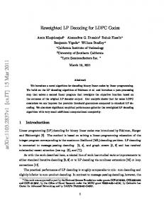
where λx , λy and λz are the three smallest magnitudes. While increasing implementation complexity, this decoding scheme almost approaches the performance of the optimal algorithm for λ = 3 at any given code rate. Therefore it is the best choice if a wide range of codes has to be supported. III. LDPC D ECODER I MPLEMENTATION The implementation of LDPC decoders is a challenging task. High throughput decoders require parallel or partly parallel architectures. These architectures are interconnectcentric due to the large amount of messages which have to be exchanged between the variable and check nodes. It is a well known fact that interconnect is a source of reliability decrease in deep submicron technology [2]. For instance, routing congestion and crosstalk yield severe timing-closure problems during placement and routing of the chip. In [13] it is reported that the routing congestion problem was the biggest challenge in the presented full parallel decoder design which was based on a 160nm technology. Nowadays 65nm technology is state-of-the-art, making the reliability problem even worse. Hence we address the reliability of the connectivity network in this paper, i.e. we consider sporadic timing errors which are induced in the connectivity network e.g. by crosstalk or soft errors. In partly parallel architectures only a subset of nodes is instantiated and the variable and check nodes are time multiplexed processed on these instantiated nodes. Hence, the number of messages transmitted per clock cycle is reduced. However, due to high throughput requirements and large block sizes, the number of instantiated nodes can be very large, e.g. 360 [14]. Figure 2 shows the partly parallel two-phase decoder architecture template that is examined in this paper. Only a subset P of variable nodes and check nodes is instantiated as variable node functional units (VFU) and check node functional units (CFU) respectively. Hence each VFU has to process N/P variable nodes and each CFU has to process M/P check nodes in a time multiplexed way. The functional units are realized in a serial manner, i.e. incoming information is processed sequentially. This provides flexibility when different node degrees have to be supported as requested by many standards. The connectivity network Π realizes the connectivity between VFUs and CFUs while the connectivity network Π−1 connects the CFUs with the VFUs inversely. Usually these networks are realized by logarithmic barrel shifters.
Fig. 2.
Partly parallel two-phase LDPC decoder architecture
IV. R ELIABILITY-AWARE D ECODING A LGORITHM In this section we describe the extensions of the LDPC decoding algorithm to make it more reliable. As mentioned in the previous section we focus on timing errors that can be induced in the connectivity networks Π and Π−1 during transmission of the messages between the functional units (see shadowed regions in Figure 2). To minimize the additional hardware overhead we exploit application knowledge to focus only on critical signals, i.e. signals which have a large impact on the system performance. Moreover we use the inherent fault tolerance behavior of the decoding algorithm. To make the decoder robust with respect to sporadic errors, 1) critical signals in the decoding algorithm have to be identified; 2) errors on a critical signal occurred during transmission have to be detected; 3) if an error is detected, some error handling has to be performed. A. Identification of Critical Signals For the check node operation sign and magnitude have to be processed independently. It can be proven that transmitting sign-magnitude values via the networks results in less power consumption. Therefore using a sign-magnitude representation for the exchanged messages in the networks is suitable. The used 3-Min decoding algorithm has some fault tolerance with respect to the magnitudes. Only the three smallest incoming magnitudes are used to calculate the outgoing magnitudes of the check nodes. Hence, depending on the check node degree, the most of the magnitudes of the incoming messages and thus potential sporadic errors in these values have no impact. In case a magnitude that is used for the
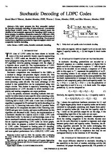
Wimax Code FER (Block Length 2304, R=1/2, 30 iterations, 3−Min algorithm)
0
10
−1
10
−2
FER
10
−3
10
Correct iBER 10−3 iBER 10−4
−4
iBER 10−3 of magnitudes
10
iBER 10−4 of magnitudes iBER 10−3 with error handling −4
iBER 10
with error handling
−5
10
1
1.2
1.4
1.6 Eb/N0 [dB]
1.8
2
2.2
Fig. 4. Communications Performance for R= 1/2 and 30 iterations depending on the induced bit error rate (iBER) in the networks Fig. 3.
Reliability-Aware modifications of the LDPC decoding algorithm
calculation of the outgoing magnitudes is affected the votes of the check node remain unaffected. Only the beliefs of the votes are distorted. In contrast a swapped sign bit results in swapped votes for all variable nodes connected to the check node. As a consequence the a posteriori information in the affected variable nodes will strongly diverge. These huge mistakes will then further propagate through the Tanner graph and probably lead to a failure of the decoding process. Therefore sign bits are by far the most important bits in the decoding algorithm. As shown in Section V the two-phase decoder approximates the communications performance of the error free architectures if we can guarantee an error free transmission of the sign bits. Design time techniques like buffering, shielding or importance-aware clock skew scheduling for the sign bits can be used to protect them. However these techniques are limited as discussed in the introduction. B. Detection of Timing Errors In [15] the authors introduced the Razor technique. The so called Razor Flip-Flop (FF) is used to detect timing errors that occur due to voltage overscaling. An additional correction mechanism afterwards even allows to restore the affected signal. However the correction tends to fail in some cases. Therefore we use the Razor FF only for timing errors detection. Since we only focus on critical signals the additional hardware overhead is expected to be fairly small. C. Error Handling In our approach we propose to handle timing errors on the algorithmic level. The LDPC decoding algorithm is therefore extended by two changes, see Figure 3. As mentioned above the sign bits are by far the most important bits of the messages. Hence only these have to be taken into account when detecting timing errors. Our first extension of the algorithm addresses the connectivity network Π between variable nodes and check nodes. It is necessary to
suppress that a check node propagates messages with wrong signs through the Tanner graph as soon as it received an erroneous sign. This can be achieved by forcing the affected check node to output only zeros for this particular iteration. Due to the transmission of LLR values this corresponds to an undecided check node that does not vote at all. The check node is thus removed from the Tanner graph for one iteration but it can take part in the decoding process in the next iteration again. Figure 3a) shows this modification for a check node of degree three. The detection of timing errors (DET) can be performed with the Razor FF. The second extension addresses the connectivity network Π−1 between check nodes and variable nodes. Since we do not want any wrong signed message to take part in the voting, i.e. the a posteriori calculation, these messages are set to zero when a timing violation was detected. In Figure 3b) the modification is depicted. This corresponds to the removal of a single edge in the Tanner graph for one iteration. Thus each single message sent to the variable nodes has to be processed separately. V. R ESULTS The results presented in this section are based on a bit true C model of the decoder using the 3-Min algorithm and 30 iterations. We assume a message quantization of 6 bits while the a posteriori information is quantized with 9 bits. Furthermore we assume that the error probability for each transmitted bit in the network is constant. Simulations have proven that there are no fundamental differences when using different error models. We investigated two different WiMAX codes [8]. The codes differ in the code rate of R = 1/2 and R = 5/6 and the degree distribution with g[7,6] = { 1/3, 2/3} for R = 1/2 and g[20] = {1} for R = 5/6. Both codes have a block length of N = 2304. The parallelism degree of the architecture is 96. For R = 1/2 we have to process 7296 edges per iteration, while for R = 5/6 the Tanner graph consists of 7680 edges.
Wimax Code FER (Block Length 2304, R=5/6, 30 iterations, 3−Min algorithm)
0
process. Our simulations have proven that these extensions result in a working decoder even when timing errors occur. The additional hardware overhead is expected to be fairly small by combining application knowledge with some modifications on the architectural level. To the best of our knowledge this is the first publication investigating the LDPC decoding algorithm in terms of implementation reliability. So far we considered timing errors injected in the connectivity networks. Further work will address reliability improvements of the check node and variable node processing as well as different error sources such as soft errors.
10
−1
10
−2
FER
10
−3
10
Correct iBER 10−3 iBER 10−4
−4
iBER 10−3 of magnitudes
10
iBER 10−4 of magnitudes
ACKNOWLEDGEMENT
iBER 10−3 with error handling −4
iBER 10
with error handling
−5
10
3
3.2
3.4
3.6 Eb/N0 [dB]
3.8
4
4.2
Fig. 5. Communications Performance for R= 5/6 and 30 iterations depending on the induced bit error rate (iBER) in the networks
Figure 4 and Figure 5 show the frame error rate (FER) for these codes under different scenarios. The FER when no errors occur at all is depicted as a reference. If we induce errors in the connectivity networks without any detection and correction mechanisms we can see an enormous impact on the decoding performance. For both codes with an induced bit error rate (iBER) in the networks of 10−3 the decoder practically refuses to work. Even an iBER of 10−4 for R = 1/2 results in a high error floor above a FER of 10−3 . Obviously error handling becomes mandatory. Furthermore we can see that errors only in the magnitudes have a very small impact on the communications performance due to the usage of the 3Min algorithm. Because of statistical imprecisions the decoder seems to even outperform the error free decoder in that case. Results when using the modified decoding algorithm presented in the previous section are shown in the same graph. We already have a great enhancement of the communications performance for a high iBER of 10−3 in the networks (code rate R = 1/2). But an error floor still exists. However for an iBER of 10−4 we can approach the performance of the error free decoder. The decoding performance for R = 5/6 behaves quite similar. For a high iBER of 10−3 the communications performance is noticeably enhanced, although there is still some error floor. For an iBER of 10−4 the decoding performance approaches the error free decoder again. VI. C ONCLUSION
AND
F UTURE W ORK
In this paper we have presented extensions of the LDPC decoding algorithm with respect to reliability issues of decoder implementations. These modifications can be used to make state-of-the-art LDPC decoder architectures more robust against timing errors in the connectivity networks. We exploited the inherent fault tolerance of the decoding algorithm and identified the most important signals of the decoding
The work presented in this paper was partially supported by the BMBF initiative EkompaSS for “Autonome Integrierte Systeme (AIS)”. R EFERENCES [1] “Reliability-Aware Microarchitecture,” IEEE micro, Nov./Dec. 2005. [2] Giovanni De Micheli, “Designing Robust Systems with Uncertain Information,” ASP-DAC 2003 Keynote Speech. [3] B. Shim and N. R. Shanbhag, “Energy-Efficient Soft Error-Tolerant Digital Signal Processing,” IEEE Transactions on Very Large Scale Integration (VLSI) Systems, vol. 14, no. 4, Apr. 2006. [4] R. Hegde and N. R. Shanbhag, “A voltage overscaled low-power digital filter IC,” IEEE Journal of Solid-State Circuits, vol. 39, pp. 388–391, Feb. 2004. [5] B. Shim, S. R. Sridhara, and N. R. Shanbhag, “Reliable low-power digital signal processing via reduced precision redundancy,” IEEE Transactions on Very Large Scale Integration (VLSI) Systems, vol. 12, pp. 497–510, May 2004. [6] Y. Liu, T. Zhang, and J. Hu, “Low Power Trellis Decoder with Overscaled Supply Voltage,” in Proc. 2006 Workshop on Signal Processing Systems (SiPS ’06), Banff, Canada, Oct. 2006, pp. 205–208. [7] IEEE 802.11n, “Wireless LAN Medium Access Control and Physical Layer specifications: Enhancements for Higher Throughput,” IEEE P802.16n/D1.0, Mar 2006. [8] IEEE 802.16e, “Air Interface for Fixed and Mobile Broadband Wireless Access Systems,” IEEE P802.16e/D12 Draft, oct 2005. [9] European Telecommunications Standards Institude (ETSI), “Digital Video Broadcasting (DVB) Second generation framing structure,channel coding and modulation systems for Broadcasting, Interactive Services, News Gathering and other broadband satellite applications; EN 302 307 V1.1.1,” www.dvb.org. [10] T. Richardson, M. Shokrollahi, and R. Urbanke, “Design of CapacityApproaching irregular Low-Density Parity-Check Codes,” IEEE Transaction on Information Theory, vol. 47, no. 2, pp. 619–637, Feb. 2001. [11] R. G. Gallager, Low-Density Parity-Check Codes. Cambridge, Massachusetts: M.I.T. Press, 1963. [12] F. Guilloud, E. Boutillon, and J. Danger, “λ-Min Decoding Algorithm of Regular and Irregular LDPC Codes,” in Proc. 3nd International Symposium on Turbo Codes & Related Topics, Brest, France, Sept. 2003, pp. 451–454. [13] A. Blanksby and C. J. Howland, “A 690-mW 1-Gb/s, Rate-1/2 LowDensity Parity-Check Code Decoder,” IEEE Journal of Solid-State Circuits, vol. 37, no. 3, pp. 404–412, Mar. 2002. [14] F. Kienle, T. Brack, and N. Wehn, “A Synthesizable IP Core for DVBS2 LDPC Code Decoding,” in Proc. 2005 Design, Automation and Test in Europe (DATE ’05), Munich, Germany, Mar. 2005. [15] D. Ernst, N. S. Kim, S. Das, S. Pant, R. Rao, T. Pham, C. Ziesler, D. Blaauw, T. Austin, K. Flautner, and T. Mudge, “Razor: A LowPower Pipeline Based on Circuit-Level Timing Speculation,” in Proc. 36th International Symposium on Microarchitecture, Dec. 2003, pp. 7– 18.