A Tool for Formal Feature Modeling Based on BDDs and Product Families Algebra Fadil Alturki and Ridha Khedri Department of Computing and Software McMaster University Hamilton, Ontario, Canada L8S 4K1 Email: turkifs,
[email protected]
Abstract—Feature models are commonly used to capture the commonality and the variability of product families. There are several feature model notations that correspondingly depict the concepts of feature modeling techniques. Therefore, the tools based on them reflect this diversity in the notations used and the fuzziness of the concepts adopted. We propose a tool based on Product Families Algebra (PFA) and on Binary Decision Diagrams (BDD). The first brings the mathematical formalism to the specifications of product families and the mathematical theory that enables calculations on featuremodels. The second brings efficient algorithms in time and in space. Hence, the tool allows several algebraic manipulations of feature models algebraically specified. The paper discusses the architecture of the tool, and the process through which a term in PFA is translated into a term formed by BDD symbols and operations. A case study is presented to illustrate the tool’s key functionalities.
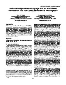
I. I NTRODUCTION In a product family, products share a group of features called commonality, but they are extended by other features called variability. Feature Modeling [1] emerged as a means to capture the commonality and the variability of the members of product families. In Feature Modeling, products are formed by aggregating features, which are, intuitively, taken as atomic characteristics or artefacts of a system. The relationships between the features in a product family are usually captured in graphs called feature models. The feature modeling step is usually an intermediate step between the requirements and the implementation of software product lines and componentbased systems. It involves finding out prominent and distinctive user visible characteristics - referred to as features - of a system as well as their structural relationships. There are several feature modeling notations that correspondingly depict the definitions and concepts of feature modeling techniques. Some of these are FODA [1], FORM [2], FeatuRSEB [3], Generative Programming [4], and PLUSS [5]. It is reported in [6] that the above feature modeling techniques are mostly extensions of the first technique FODA. Figure 1 illustrates the evolution of feature modeling techniques starting from FODA. Some of the feature modeling techniques are widely used and investigated by researchers, and several tools have been This research is supported by Natural Sciences and Engineering Research Council of Canada (NSERC) through the project 2009R00030.
Fig. 1.
Extension Hierarchy of Feature Modeling Techniques
developed to support them. According to the evaluation of the feature modeling tools discussed in the survey presented in [7], the most prominent feature modeling tools are: RequiLine, Pure::Variants, XFeature, and DOORS TREK. The survey [7] points also to other tools such as AmmiEddi, Captain Feature, DecisionKing, Feature Plugin, FMP, FORM/ASADAL, Gears, SSEP Toolset, and VarMod. According to [7], none of the tools reviewed implement the classical feature modeling concepts except for XFeature and some tools implement other concepts such as the separation between feature models and family models as for Pure::Variants and Requiline. Even though they share some common background, they do not produce the same feature models. We have found other tools in the literature that provide some support for feature modeling. The tool 001 [8] is essentially an integrated family of utilities used for rapid development of systems. One of its utilities supports feature modeling. The feature model in 001 is based on FODA and uses a representation called 001 TMap with more capabilities to capture information and enhance the FODA technique [8]. Each of these tools support a specific feature modeling technique and is limited to its specific notation. It cannot allow specifiers to overcome the limitations of one technique by adopting another technique without switching to the corresponding tools of the latter. In addition to the differences in the semantics of the feature models adopted, there is no standard language via which these tools can exchange feature models. All the tools are based on informal understanding of the notions of products, and families. The lack of formal definitions of concepts such as “family”, and “product” as
well as the relationship between features and products lead to ambiguities and to conflicting terminology. We find in the work on product families algebra [9]–[11] the mathematical background for proposing a tool that uses the language of this algebra as a common language for several feature modeling techniques. A feature model produced by a modeling technique can be translated (syntax-based translation) into terms of the language of the algebra. On the obtained terms, one can perform mathematical transformations such as simplification, factorisation, combination with, or comparison to other terms. The terms can also be translated into other feature models that use a different graphical notation from the original. For instance, a FODA feature model can be translated into an algebraic term, then it can be displayed as a PLUSS feature model. We would like to stress the fact that once a feature model is expressed with terms within the language of PFA, it can then be subject to algebraic manipulations. In other words, we can do calculus on models, because calculus is algebra (for the relationship between calculus and algebra, we refer the reader to [12]). Therefore, the proposed tool would help in doing calculus on feature models through their translation into terms of the product families algebra that we introduce in Section II-A. The graphical feature modeling techniques presented above do not facilitate any calculational means. It would be hard for users to do any kind of predictions, or inquiries. There is no direct way to get, for example, a list of fault products, or products that are mutually exclusive. These techniques do not allow to calculate the number of unique products possible with certain constraints. To do so, an exhaustive traversal of graphs has to be done without any sort of formalism. One more problem comes with one of the major benefits of feature models. As much the visualization is beneficial, it could be an obstacle when we handle large systems. The complete picture is incomprehensible even though there are some techniques to zoom in and navigate the graph or represent the feature model as a tree that is collapsible and expandable. A. Main Contribution The presented work proposes a tool that we coined Jory, which bases the automation of feature modeling activities on Product Families Algebra and on Binary Decision Diagrams. The first brings the mathematical formalism to the specifications of product families as well as the mathematical theory that enables calculations on feature-models. The second brings efficient algorithms in time and in space, which allow the handling of feature models involving large number of features. To provide automated support to users engaged in featuremodeling, the tool architecture contains an architectural layer capable of translating between feature models of different notations. Moreover, the tool allows several algebraic manipulations of feature models presented as algebraic terms. A feature model can be, for instance, simplified, factorised, and mathematically analysed. Also, feature models can be combined, linked, extracted and enumerated. We conjecture
that this should provide more functionality that can be applied to feature models and can extend their benefits. Instead of being ”yet another tool”, the proposed tool provides in addition to its algebraic flavour an environment that recognises other feature modeling notations and allows them to exchange models through translation. The translation is done through an algebraic setting that has a wide literature and can inherit a wealth of theories from classic algebra. B. Organisation of the paper We start by laying the theoretical background on which the construction of the proposed tool stands. We briefly introduce PFA and BDDs. We also give two models of PFA that the tool use in validating formulas within the language of PFA. In Section III, we give the highlights of Jory’s design and describe the functionalities of its architectural layers. We put more emphasis on explaining the mathematics behind the detailed design of the Term Evaluation Layer and the BDD Layer. In Section IV, we present and discuss a simple case study to illustrate the use of the tool and its main functionalities. In Section V, we conclude and point to further extensions and improvements to the tool. II. M ATHEMATICAL BACKGROUND The tool that we present in this paper is based on two mathematical paradigms: product families algebra (PFA) and binary decision diagrams (BDDs). The language of the first is used to specify product families and its theory enables calculations on product families. BDDs are for the purpose of the implementation of two specific models for product families algebra: the set model and the bag (multiset) model. We briefly introduce PFA and BDDs in the rest of this section. A. A Brief Overview of Product Families Algebra The adoption of product families aims at recognising a reality in software development industry noticed decades ago [13]: economical constraints impose a concurrent approach to software development replacing the early sequential one. A review of the literature reveals a wide set of notions and terms used without formal definitions. Terms like product, family and subfamily lack rigourous definitions. In [9], [14], we find the algebraic definitions for these terms that we adopt for the rest of this paper. Also, within specific models (such as setbased model and bag-based model), the above papers provide the corresponding definitions of these notions in terms of these particular models. The work presented in [9]–[11] shows through several examples, the simplicity with which product families algebra can contribute towards the establishment of a solid mathematical background for a formal product families specification. It is based on a classical mathematical structure, which is the idempotent commutative semiring. Therefore, it inherits all the mathematical theory of idempotent semirings and provides us with a calculational power that can be applied to feature models. It also inherits the mathematical properties of sets and bags when we use their corresponding models for our algebra.
Definition 2.1: A semiring is a quintuple F = (S, +, 0, ·, 1) such that (S, +, 0) is a commutative monoid and (S, ·, 1) is a monoid such that · distributes over + and 0 is an annihilator, i.e., 0 · a = 0 = a · 0. The semiring is commutative if · is commutative and it is idempotent if + is idempotent, i.e., a + def a = a. In the latter case the relation a ≤ b ⇐⇒ a + b = b is a partial order, i.e., a reflexive, antisymmetric and transitive relation, called the natural order on S. It has 0 as its least element. Moreover, + and · are isotone with respect to ≤. In the context of software family specification, + can be interpreted as a choice between options of products and features, and · as their composition or mandatory presence. In [9]–[11], [14], an idempotent commutative semiring is called a product families algebra or a feature algebra. Its elements are termed product families and can be considered abstractly as representing sets of products, each of which is composed of a number of features. Definition 2.2: A product family algebra (PFA) is an idempotent and commutative semiring. Its elements are called product families or briefly families. A family g is a subfamily of family f iff g ≤ f , where ≤ is the natural semiring order. The language of PFA is used for feature modeling. A special family is 1 = {∅} consisting just of the empty product that has no features. The term 1 + a denotes a family which consists of all products of a and the empty product; it expresses optionality of a. As a simple example we assume a company which produces computers. It builds machines with a hard disk and a screen. Moreover, clients might request a second screen, a printer or a scanner. Of course, it is possible to have more than one extension for the basic computer. Using the abbreviations hd, scr, prn, and scn, this yields the following product family in PFA: hw = hd · scr · (1 + scn) · (1 + prn) · (1 + scr) Note that according to this general definition, the members of a product family need not have common features. In [9]– [11], a product family that share a common feature f is called f -carrying family. In [9]–[11], two models for the Product Families algebra are explicitly given: the set-based model and the bag-based model. We also note that Boolean algebras and lattices can also be models for the product families algebra. The proposed tool implements the set-based model and the bag-based model. In the following, we briefly present them as given in [9]–[11]. 1) The Set-based Model: Let IF be a set of arbitrary elements or the so-called features. Often, features can be seen as basic properties of products. The set of all possible products def is denoted by IP = P(IF). A collection (set) of features is a product. A collection of products (an element of P(IP)) is called product family. On product families we define an operation · which is a composition or a merging operator for all features:
The second operation + offers a choice between products of different product families: + : P(IP) × P(IP) → P +Q
P ·Q
=
P(IP) {p ∪ q : p ∈ P, q ∈ Q} .
P(IP) P ∪ Q.
It is straight forward to see that the structure (IP, +, ∅, ·, {∅}) is a model for the product families algebra, where · and + are the operation defined on sets as given above. 2) The Bag-based Model: The set-based model does not allow multiple occurrences of the same feature in a product. For example, the above hw family cannot be fully captured within a set-based model because we need products with two occurrences of the feature scr. If the number of occurrences of a feature can be higher than 1, one can use an analogous model that employs multisets (also called bags) of features. In a similar way to set-based model, on product families we define an operation · which is a composition or a merging operator for all features: · : P(IP) × P(IP) → P ·Q
=
P(IP) {p t q : p ∈ P, q ∈ Q}
where t denotes bag union that takes into account the number of occurrences of an element of a bag. The second operation + is the same as that defined for the set-model. 3) Further Notions: For the mathematical background of the rest of the paper, we need to recall other notions already presented in [9]–[11]. Definition 2.3: An element a is said to be a product, if a 6= 0 and ∀(b |: b ≤ a =⇒ b = 0 ∨ b = a ) ∧ ∀(b, c |: a ≤ b + c =⇒ (a ≤ b ∨ a ≤ c) ) .
(1)
We say that a is a proper product if a 6= 0. Intuitively, this means that a product cannot be divided using the choice operator +. Or in other terms, it does not offer optional or alternative features. In this case, a is also a product if a = 1. Analogously to Definition 2.3, indivisibility is required, but this time w.r.t. multiplication rather than addition. Definition 2.4: An element a is called feature if it is a proper product and it is different from 1 and ∀(b |: b | a =⇒ b = 0 ∨ b = a ) ∧ ∀(b, c |: a | (b · c) =⇒ (a | b ∨ a | c) ) ,
(2) def
where the divisibility relation | is given by x | y ⇐⇒ ∃(z |: x = y · z ). On every product families algebra, we can define a relation that expresses that one product family refines another in a certain sense. Definition 2.5: [ [9], [14]] The refinement relation v on a product families algebra is defined as def
· : P(IP) × P(IP) →
=
a v b ⇐⇒
∃(c | c ∈ S : a ≤ b · c ) ,
where ≤ is the natural order on S.
Roughly speaking, a v b means that every product in a has at least all the features of some product in b, but possibly additional ones. For example, in the above hw family, the product given by the term hd · scr · scn · prn refines the product given by the term hd · scr · prn, since the first has scn in addition to all the features of the second. p We write a → b to denote that a requires b in the family p. Definition 2.6: [ [10], [11]] Assume a feature-generated algebra. For elements a, b, c, d and product p we define, in a family-induction style, a→b
p
def
⇔
(p v a ⇒ p v b) ,
c+d
def
a→b ∧ a→b.
a → b
⇔
c
d
In [10], [11], the reader finds the mathematical properties of this operator. For further discussions on these notions, we refer the reader to [9]–[11] from where the above definitions are adapted. In the latter references, the reader can find as well more properties of the product families algebra concerning finding common features, building up product families, finding new products and excluding special feature combinations. To give the reader an idea about the expressiveness of the language of the product families algebra, we provide in Table I the algebraic term(s) that correspond(s) to the primitive expressions used in FODA, FORM, FOPLE, FeatuRSEB, GP, van Gurp, Reibisch, and PLUSS. For example in Table I, the forth row, is the expression of a product a that is composed of b, c and d. The expression is given in the various feature models as well as in PFA. B. Binary Decision Diagrams A Binary Decision Diagram (BDD) is a finite directed acyclic graph with a unique initial node, where all terminal nodes are labelled with 0 or 1 and all non-terminal nodes are labelled with a node names. Each non-terminal node has exactly two edges: one labelled false and one labelled true and represented as a dashed line and a solid line, respectively. For more details on BDDs, we refer the reader to [15, Chapter 6], [16]–[19]. Binary Decision Diagrams were first used in digital circuits before they are adapted in Model Checking and many other applications. BDDs are used to represent boolean functions. If we take the boolean function f (x, y, z) = x · y ∨ z defined on the Boolean variables x, y, and z, then the BDD that represents f is given in Figure 2. We use ·, ∨, and to denote respectively the Boolean operators and, or, and the complement, respectively. When a boolean function evaluates to true, then its corresponding combination of nodes on a path starting from the root ends in a true terminal node. In this case, we say that the boolean function is satisfied. We are using Reduced Ordered Binary Decision Diagrams, where nodes are ordered and any sort of duplication is removed.
Fig. 2.
The BDD representing the Boolean function f (x, y, z) = x · y ∨ z
III. T OOL D ESIGN A. Architecture Design In designing the proposed tool, that we coined Jory, we opted for a layered architecture. This architectural style is suitable for our need for the following reasons: • It enables incremental development of the tool based on increased levels of abstractions. For instance, each layer in our system (other than the user interface layer) corresponds to a level of abstraction. • It enhances independence among layers: no impact from the changes of lower services as long as their interface to the other layers is preserved. • It is suitable for plug-and-play of new components. Indeed, we intend to make use of other models for features other than BDDs to enable feature interaction problems. Several feature interaction detection tools such as [20] have been developed and we intend to enable our tool to seek some of their services. B. Main Tool functionalities The main services provided by the tool are related to feature models transformations, PFA calculation and rewriting, merging, translation into PFA algebraic specification, or to several other graphical feature models. Each layer of the tool (see Figure 3) specialises in a set of related activities. We discuss the architectural layers in the remaining of this section. We put more emphasis on Term Evaluation Layer and on BDD Layer. These two layer are special due to mathematics involved in their design. The other layers are either simple switching system (e.g., Concrete Models Layer), or involve direct syntactical translation (e.g., Translation Layer). 1) User Interface Layer: The User Interface Layer supports the display and the input of graphical and textual feature models. In Section IV, the reader finds several figures showing the user interface. Its design is simple and straightforward.
textual
textual
Requires
Excludes textual
textual
textual
textual
textual
textual
UML Multiplicities
not supported
not supported
OR - Choice not supported
UML Multiplicities
XOR - Alternative
a = (1 + b) · (1 + c) · (1 + d) ∧ ¬(a 6 1) Let p be a family, we p have a → b. Let p be a family, a · b = 0
a=b+c+d
a=b·c·d UML Multiplicities
Product Families Algebra Term
AND Composed-of
PLUSS
Let p be a family, p = a+1
Reibisch
, & multiplicities
van Gurp
Optional
GP
Let p be a family, p = a
FeatuRSEB
, and multiplicities
FOPLE
Mandatory
FORM
a
FODA
Feature
Expression
TABLE I F EATURE M ODELLING N OTATIONS AND THE C ORRESPONDING A LGEBRAIC T ERMS
h 1 is the identity for · i (scr + scr · scn) · (1 + prn) · (1 + scr) = h Distributivity of · over +, and the fact that 1c is the identity for · i (scr + scr · prn + scr · scn + scr · scn · prn) ·(1 + scr) = h Distributivity of · over +, and the fact that 1c is the identity for · i scr (1) +scr · prn (2) +scr · scn (3) +scr · scn · prn (4) +scr · prn (5) +scr · prn · prn (6) +scr · scn · prn (7) +scr · scn · prn · prn (8) =
Fig. 3.
The main layers of the tool’s architecture
2) Translation Layer: The Translation Layer allows to translate Graphviz DOT code (used for plain text description of graphical feature models) into terms in the language of product families algebra. The translation is syntax-based translation. Through the services of the Translation Layer, the tool serves as a bridge between several feature model techniques. Using the corresponding term(s) to each graphical element of a graphical feature model (as given in Table I), every feature diagram can be transformed into an algebraic expression using a bottom-up traversal. This recursive method translates each subtree into an algebraic expression, starting from the leaf nodes going up to the root. The result is unique up to commutativity and associativity of the semiring operators. Once we have the algebraic terms corresponding to a feature model, we can perform algebraic operations on them. For instance, we can simplify the term or re-factor it and then redisplay the corresponding graphical feature model. 3) Term Evaluation Layer: The Term Evaluation Layer is responsible for the two critical tool activities: (1) term rewriting, and (2) the evaluation of Product families terms into a concrete model. Term Rewriting The first activity allows calculations on product families. For instance, if we take the example about a hardware family hw given in Section II-A, through algebraic rewriting, one can compute the list of products of this family as follows: hw h As defined in Section II-A i hd · scr · (1 + scn) · (1 + prn) · (1 + scr) = h Distributivity of · over + i (scr · 1 + scr · scn) · (1 + prn) · (1 + scr)
=
At the end of the above derivation, we have an PFA term that gives the eight members of the hw family. To find the commonality of the members of the product family hw, we simply calculate the the greatest common divider (GCD) of all its members. In this case, it is easy to see that the GCD(hw) is the product scr. In complex cases, the common algorithm for finding the the GCD is used. It is a known algorithm with known complexity; it is well known that gcd(m, n) ∈ O(ln(n)) for natural numbers m and n. On the other hand, finding commonality using diagrams is more complex. Similar calculations are used to eliminate the members of a family that do not satisfy a constraint. For example, to state that two features are incompatible, we simply write that their product is the product 0. For example, if, in the above hw example, we want to exclude the products containing scn and prn, we write scn · prn = 0. Then, the above derivation, would continue as follows: hw h Per the above calculation i scr + scr · prn + scr · scn +scr · scn · prn + scr · prn +scr · prn · prn + scr · scn · prn +scr · scn · prn · prn = h scn · prn = 0 i scr + scr · prn + scr · scn +scr · 0 + scr · prn + scr · prn · prn +scr · 0 + scr · 0 · prn = h 0 is an annihilator for · i scr + scr · prn + scr · scn + 0 + scr · prn +scr · prn · prn + 0 + 0
=
=
h 0 is neutral for + i (1) (2) (3) (5) (6)
scr +scr · prn +scr · scn +scr · prn +scr · prn · prn
Hence, only the products numbers (1), (2), (3), (5), and (6) satisfy the constraint. We note that PFA allows more complex constraints that we will discuss later when we use the tool on a case study. This kind of algebraic manipulation is the first responsibility of the Term Evaluation Layer. The Evaluation of Product Families Terms into a Concrete Model The evaluation of terms with and without variables in a given algebra is a common topic in algebraic specification. In [21, Chapter 1], the reader finds an exhaustive discussion on this issue. We give here the essentials for the presentation of our tool. In our case the signature of the product families algebra is (S, +, 0, ·, 1) as given in Definition 2.1. A signature gives mainly the set of sorts (in our case it is a set of product families), and a set of operators and their arities. The set of operations for this algebra is OP = {+, 0, ·, 1} (constants are considered as operations of arity 0). A term that is written according to the signature of the product families algebra can be translated to a corresponding term within the language of its models (or any algebra with the same signature SIG-algebra). The following definition gives the evaluation of a term in the product families algebra into one of its models that use BDDs (i.e., set or bag models). Definition 3.1: (a) Let TOP be the set of ground terms of a signature F = (S, +, 0, ·, 1) as given in Definition 2.1. Let B = (B, plus bdd, zero bdd, dot bdd, one bdd) be a model for F where the elements of B are sets of BDDs. The evaluation eval : TOP −→ B is recursively defined by (i) For all constant symbols N ∈ {0, 1}, we define eval(N ) as follows: eval(0) = zero bdd eval(1) = one bdd (ii) For all No (t1 , t2 ) ∈ TOP , where No ∈ {+, ·} is a 2-arity operation symbol, we define eval(No (t1 , t2 )) as follows: eval(+(t1 , t2 )) = plus bdd(eval(t1 ), eval(t2 )) eval(·(t1 , t2 )) = dot bdd(eval(t1 ), eval(t2 )) (b) Given a set of variables X for SIG = (S, OP) and an assignment ass : X −→ B
with ass(x) ∈ B for x ∈ X. The extended assignment, or simply extension ass : TOP −→ B of the assignment ass : X −→ B is recursively defined by (i) ass(x) = ass(x), for all variables x ∈ X ass(x) = eval(No ), for all constant symbol No ∈ {0, 1} (ii) ass(No (t1 , t2 )) = eval(No )(ass(t1 ), ass(t2 )), for all No (t1 , t2 ) ∈ TOP (X), which is the set of terms containing variables from X. The Definition 3.1 gives a straight forward mechanism to move from a specification of a product family in the product families algebra into its BDD corresponding. It translates a term within the language of the product families algebra into a term within the language of its model B. The zero bdd is the empty set. The one bdd is a set that contains a BDD that represents either the empty set in the set model, or the empty bag in the bag model. The empty set and the empty bag are both represented by the BuDDy bddfalse. Definition 3.1 is indeed implemented to evaluate a PFAterm in its corresponding in a model for PFA. The operation plus bdd and dot bdd are defined as a combination of operations on BDDs representing set or bag (as we discussed in Section II-B) and that according to wether we are in a set model or a bag model. We note that plus bdd is the same for both models. 4) Concrete Models Layer: The most important layer is the Concrete Models Layer. It allows the transformation of an abstract feature model into several concrete models. For instance, some models may involve the specification of a feature (e.g., as a finite state machine or using another formalism) or they simply indicate the presence or absence of a feature, and the relationships among features. In the current version of the tool we have the two models discussed in Section II: the set-based model and the bagbased model. The first is suitable for capturing abstract feature models that do not not allow duplication of features within a product. The second is used when a feature can have several occurrences in a product. this situation can be found in hardware product families. 5) BDD Layer: The BDD Layer allows to code product families expressed by a term resulting from the transformation of the Concrete Models Layer into a BDD. The code of this layer uses BDD Buddy library, which we considered particularly useful for our purposes because of the exhaustive list of basic functions it provides. BuDDy can handle up to 50, 000 nodes in every megabyte of memory. The decision making per path is polynomial with regards to the number of variables used in a BDD. According to [22], it can handle efficiently up to 232 nodes assuming there is no limit on the memory resources. In Subsection II-A1, we laid out a concrete representation of the operations and constants of PFA in terms of operations
on sets and bags. Therefore, simple representation of sets and bags with BDDs should lead straight forward to a representation of terms within the language of PFA in terms of BDDs. In the following, we discuss the representation of sets and bags with BDDs. Let IF be a finite set of arbitrary features denoted by f1 , · · · , fn . The boolean expression that corresponds to the set {f3 , f5 } is f1 f2 f3 f4 f6 · · · fn ∨ f1 f2 f3 f4 f5 f6 · · · fn . So, in this expression, the feature names play the role of boolean variables. The term fi indicates the absence of the feature fi . Figure 4 shows the BDD corresponding to the set {f3 , f5 } with IF is limited to 6 features (i.e., n = 6).
Fig. 5.
Fig. 4.
The BDD for the set {f3 , f5 }
While the representation of sets using BDDs is straight forward, the representation of bags is quite challenging. The BDD libraries such as BuDDy [23] do not provide support for representing bags as BDDs. We articulated a representation of a bag by encoding cardinalities of elements in the bag within the BDD. For encoding the cardinality, we take in addition to IF another set that we denote by C. The elements of def C = {v0 , v1 , · · · , vm } are used to encode (in binary code) the number of occurrences of a feature in the bag. For example, for m = 2 (i.e., C = {v0 , v1 , v2 }) the bag {| f3 , f3 , f3 , f5 , f5 |} can be represented as follows: f1 f2 f3 f4 f6 · · · fn v0 v1 v2 ∨ f1 f2 f3 f4 f5 f6 · · · fn v0 v1 v2 The sub-term v0 v1 v2 encodes 011, which is the binary representation of the number of occurrences of f3 . Figure 5 shows the BDD corresponding to the bag {| f3 , f3 , f3 , f5 , f5 |} with def IF is limited to 6 features (i.e., n = 6) and C = {v0 , v1 , v2 }.
The BDD for the bag {| f3 , f3 , f3 , f5 , f5 |}
The size of C determines the maximum number of occurrences allowed within a bag. When the cardinality of C is m, we can represent bags with a maximum of 2m − 1 number of occurrences of its elements. This representation enables the implementation of the operations on sets and bags based on BDD operations. The following code gives the implementation of set union using BDDs, where set union is simply expressed as the operation | (i.e., or) on BDDs. bdd setUnion(bdd s1, bdd s2){ bdd u; u = s1 | s2; return u; } On the other hand, set intersection is implemented as the operation & on BDDs. bdd setIntersection(bdd s1, bdd s2){ bdd u; u = s1 & s2; return u; }
We would like to point that, for instance in the set model, a product family is a set of sets. To handle BDDs, we use the BDD library, BuDDy, developed by Jørn Lind-Nielsen. BuDDy library is proven to be more efficient compared to other available libraries [24]. In the set model, a node is associated to a feature. In the bag model, we use some of the nodes to encode the number of occurrences. Therefore, we expect to handle 232 − m features, where m is the number of nodes used to encode the number of occurrences of a feature in a product. With m = 10, we can handle number of occurrences ranging from 1 to 1024. IV. I LLUSTRATIVE E XAMPLE We present a simple example to illustrate how the tool translates the feature model into a term in the language of the product families algebra. It then uses BDDs to implement the algebraic operations and to decide the relations defined on product families. The following example is adapted from a Human Resource System Requirements Specification that can be found in [25]. The reader should notice that some collections of features are essential (i.e., mandatory), while others are not. For instance, ”Internet/intranet enabled ESS systems“ set of features is essential to all member of the family; we point to it by placing ”Essential“ beside it in Table II, which summarises the general structure of the family. TABLE II E MPLOYEE S ELF S ERVICE (ESS) S OFTWARE FAMILY Collection of Features Internet/intranet enabled ESS systems
ESS - basic personal tasks
ESS - time and attendance tasks
Features 1) Personal Info 2) Personal Info Flexibility
Ess.l/Opt./Alt.
The FODA diagram corresponding to employee self service
1) Essential 2) Essential
1) 2) 3) 4)
Basic Personal Tasks Update Personal Info Employment History HR Policies
1) 2) 3) 4)
Essential Essential Essential Essential
1) 2) 3) 4) 5) 6)
Time Management Absence Management Absence Information Absence Calender Holiday Entitlement Holiday Administration
1) 2) 3) 4) 5) 6)
Optional Optional Optional Optional Optional Optional
ESS - expenses tasks
ESS - payroll and benefits tasks
Fig. 6.
1) Expenses Tasks
1) Optional
1) Payroll Administration 2) Either Benefit Display or Multi Benefit Programs
1) Optional 2) Alternatives
The FODA feature model corresponding to the Employee Self Service (ESS) Software Family is given in Figure 6. A. Formal Specification of a Family The algebraic term corresponding to the above family is the following:
ESS = Personal Info · Personal Info Flexibility ·Basic Personal Tasks · Update Personal Info ·Employment History · HR Policies ·(1 + Time Management) · (1 + Absence Management) ·(1 + Absence Information · (1 + Absence Calender)) ·(1 + Holiday Entitlement · (1 + Holiday Administration)) ·(1 + Expenses Tasks) · (1 + Payroll Administration) ·(Benefit Display + Multi Benefit Programs)
The above FODA diagram can be translated into a structured PFA specification. In the following, we provide the structured specification of the ESS family that can be directly loaded to our tool. It can be either obtained through the translation from a graphical model or directly written in the language of PFA. #List of basic features bf personal_info % personal information bf personal_info_flexibility % personal info flexibility bf basic_personal_tasks % basic personal tasks bf update_personal_info % update personal info bf employment_history % employment history bf hr_policies % hr policies bf time_management % time management bf absence_management % absence management bf absence_information % absence information bf absence_calendar % absence calendar bf holiday_entitlement % holiday entitlement
bf holiday_administration % holiday administration bf expense_tasks % expense tasks bf payroll_administration % payroll administration bf benefit_display % benefit display bf multi_benefit_programs % multi-benefit programs # End of the list of basic features #------#Hierarchical presentation of the product family #-# internet intranet enabled ess internet_intranet_enable_ess = ( personal_info. personal_info_flexibility) # ess basic personal tasks ess_basic_personal_tasks = (( basic_personal_tasks . update_personal_info) . (employment_history . hr_policies)) # ess time and attendance tasks ess_time_and_attendance_tasks = ( ( ( 1 + time_management ) . ( 1 + absence_management ) ) . ( ( 1 + ( absence_information . ( 1 + absence_calendar ) ) ) . ( 1 + ( holiday_entitlement . ( 1 + holiday_administration ) ) ) ) )
Fig. 7. Jory interface showing the specification of the family employee self service and the constraint applied to it
# ess payroll and benefits tasks ess_payroll_and_benefits_tasks = ( ( 1 + payroll_administration ) . ( 1 + ( benefit_display + multi_benefit_programs ) ) ) # employee self service whole system employee_self_service = ( internet_intranet_enable_ess . ess_basic_personal_tasks . ess_time_and_attendance_tasks . ( ( 1 + expense_tasks ) . ess_payroll_and_benefits_tasks ) )
In the above specification, the keyword ”bf ” precedes a basic feature. The ”%” and ”#” symbols are used to introduce a comment. A string preceded by a % symbol is a comment that the system stores, while that preceded by a # symbol is completely ignored and is intended to simply document the specification. The tool allows the analysis of the product families given by a specification similar to the above one. For instance, a user can request the list of the common features of two or all the products of a product family. Figure 9 gives the result of the commonality of the families employee self service. All the members of this family share the features personal inf, personal info flexibility, basic personal tasks, update personal info, employment history, and hr policies. We find that this family contains 432 potential members. Some of them are not going to be genuine products due to possible undesirable feature interactions. This number illustrates the combinatoric complexity in product families. The multitude of the product family variation within a product family model is a real limitation of product families modelling. The remedies for this shortcoming are prescribed in the literature through three approaches. The first is a combination of modularity, encapsulation, and aspects [26]. The second is a combination of composition and hierarchy [26]. The third is to use the feature model as a pattern for integrating the specifications of each of the features and then for the elimination of the combinations of features that present conflicting behaviours [27]. The proposed tool is based on PFA that allows modularity and encapsulation. For instance, in the
Fig. 8. Jory interface showing the size of the constrained family employee self service
above example, the specification of the employee self service illustrates these characteristics. The paper [10] gives several examples on the capabilities of PFA in dealing with combining orthogonal views of a product family, which relates to the second remedy. When a feature has a formal specification such as a Z schema or a finite state machine, then it is easy to define concrete feature composition and selection (i.e., ·, +) that would enable us to remove inconsistent features. For example, when a feature is given by its Z schema, the operation · can be schema integration. The proposed tool, then would be extended by a model that captures this new meaning for the operators of the algebra PFA. At its current state, the tool provides the basic operations on product families. It allows to obtain the size, and the list of the products of a family. It computes as well the commonality of the products of a family. It answers questions such as whether a family a is a subfamily of family b, or whether a refines b. It allows as well to apply a constraint on a product family. For
Fig. 11. Fig. 9.
Usage of Refines function of Jory
Commonality of the family employee self service
instance, if we require that each time we have the feature payroll administration in the family employee self service, we should have the feature holiday administration. Figure 7 illustrates how this constraint is provided to the system in the field ”Parameters” of the user interface. Then we can perform all the operations provided by the tool on the restricted family. For instance the family employee self service with the above constraint contains 288 products (as shown in figure 8), while without any constraint it contains 432 products. Figure 10 is the screen-shot that gives the answer of the tool when asked whether the family time management is a subfamily of ess time and attendance tasks. The tool returns ”yes” for true and ”no” for f alse.
integration constraints of view giving partial specification of a family are defined using the notions of refinement of Definition 2.5. Sets of integration constraints that link (families of) system features in one view to other (families of) features in the same or a different view are used in reducing the size of a family by removing the products that do not satisfy the integration constraints. Both, families and constraints, are formalised using a product family algebra. To check the adequacy of PFA, a prototype implementation [14] of the bag model has been written in the functional programming language Haskell. In this prototype, features are simply encoded as strings. Bags are represented as ordered lists and · as bag union by merging. Sets of bags are implemented as repetition-free ordered lists and + as repetitionremoving merge. This prototype can normalise algebraic expressions over features into a sum-of-products-form. We used this prototype tool to perform parallel testing on our tool. Both systems are provided with the same input and the result as well as the performance are compared. Jory has higher performance than the Haskell prototype. It is faster due to use of BDDs and it can handle larger product families. V. C ONCLUSION AND F UTURE W ORK
Fig. 10.
Usage of IsSubFamily function of Jory
Figure 11 shows the result obtained for the proposition internet intranet enable ess v personal info Based on these basic functions of the system, one can perform more complex analysis tasks. For instance, in [10]
The proposed tool is based on an algebra that captures the inherent properties of product families. At its current state, It proposes two models to reason on product families. When the composition of features is idempotent then, one should use the set-based model. When the number of occurrences of a feature is relevant (i.e., the composition of features is not idempotent), then the bag-model is recommended. This situation is found in dealing with hardware features for instance. A robot with four wheels is a different product from the one with two wheels. The tool’s design allows adding other models. For instance, a feature might be instantiated as a Z schema and the operation ·, and + can be evaluated into operations on schema. We aim at extending the tool with other concrete models for the product families algebra that would allow us to reveal feature interactions at a concrete level.
The most recent tools introduced in the literature deal with feature based reasoning or configuration and are based on theorem provers and some of them on BDDs [28]. However, they use BDDs to implement proposition logic reasoning. With its Translation Layer, Jory serves as a bridge between several feature modelling techniques. It gives users the option of using a graphical feature-modelling with the benefits of the calculational power of algebra. Currently, the development of the Translation Layer is a work in progress. Our future development activities related to Jory is the development of a high level language based on PFA to easily specify complex product families without using the basic PFA constructs. It would allow shorter specifications. In [9]–[11], the reader can find several constructs of the sought language. For example, the optionality of a feature (or, more generally, a list of products) can be specified by opt[s1 , . . . , sn ] instead of writing (1 + s1 ) · · · (1 + sn ). Or, one can write an instead of writing a · a . . . · a to express that the feature a is present n times. Hence, to express that a feature a is present at most n times in a product, one would n write opt[a] . The semantics of this sought language would be given by the product families algebra (or one of its models). Also, we intend extend Jory by models that involves techniques for detecting feature interactions. Several of these techniques have been developed in the nineties. They were intended to deal with single products. We can extend them to product families. R EFERENCES [1] K. Kang, S. Cohen, J. Hess, W. Novak, and S. Peterson, “Featureoriented domain analysis (FODA) feasibility study,” Software Engineering Institute, Carnegie Mellon University, Tech. Rep., November 1990. [2] K. C. Kang, S. Kim, J. Lee, K. Kim, E. Shin, and M. Huh, “FORM: A feature-oriented reuse method with domain-specific reference architectures,” Ann. Software Eng, vol. 5, pp. 143–168, 1998. [3] M. L. Griss, J. Favaro, and M. d’Allessandro, “Integrating feature modeling with the RSEB,” in Proceedings: Fifth International Conference on Software Reuse, P. Devanbu and J. Poulin, Eds. IEEE Computer Society Press, 1998, pp. 76–85. [4] K. Czarnecki and U. Eisenecker, Generative programming: methods, tools, and applications. ACM Press/Addison-Wesley Publishing Co. New York, NY, USA, 2000. [5] M. Eriksson, J. B¨orstler, and K. Borg, “The PLUSS approach - domain modeling with features, use cases and use case realizations,” in Software Product Lines, 9th International Conference, SPLC 2005, Rennes, France, September 26-29, 2005, Proceedings, ser. Lecture Notes in Computer Science, J. H. Obbink and K. Pohl, Eds., vol. 3714. Springer, 2005, pp. 33–44. [6] P. Schobbens, P. Heymans, J. Trigaux, and Y. Bontemps, “Generic semantics of feature diagrams,” Computer Networks, vol. 51, no. 2, pp. 456–479, 2007. [7] O. Djebbi, C. Salinesi, and G. Fanmuy, “Industry survey of product lines management tools: Requirements, qualities and open issues,” in Requirements Engineering Conference, 2007. RE ’07. 15th IEEE International, 2007, pp. 301–306. [8] R. Krut, “Integrating 001 tool support into the feature-oriented domain analysis methodology,” Software Engineering Institute, Carnegie Mellon University, Tech. Rep. CMU/SEI-93-TR-11, May 1993. [9] P. H¨ofner, R. Khedri, and B. M¨oller, “Feature algebras,” in FM 2006: Formal Methods, ser. Lecture Notes in Computer Science series, J. Misra, T. Nipkow, and E. Sekerinski, Eds., vol. 4085. 14th International Symposium on Formal Methods, McMaster University, Hamilton, Ontario, Canada: Springer, August 21 - 27 2006, pp. 300–315.
[10] ——, “Algebraic view reconciliation,” in 6th IEEE International Conferences on Software Engineering and Formal Methods. Cape Town, South Africa, November 10-14, 2008, pp. 85–94. [11] ——, “An algebra of product families,” Software and Systems Modeling, p. 36, 2009, in press. [12] W. S. Hatcher, “Calculus is algebra,” The American Mathematical Monthly, vol. 89, no. 6, pp. 362–370, Jun. – Jul. 1982. [13] D. L. Parnas, “On the design and development of program families,” IEEE Transactions on Software Engineering, vol. SE2, no. 1, pp. 1–9, 1976. [14] P. H¨ofner, R. Khedri, and B. M¨oller, “Feature algebra,” Institut f¨ur Informatik, Universit¨at Augsburg, Tech. Rep. Report 200604, February 2006, (Last accessed March 05, 2010). [Online]. Available: http://www.informatik.uni-augsburg.de/lehrstuehle/dbis/pmi/ publications%/all pmi tech-reports/tr-2006-4 hoe khe moe [15] M. R. A. Huth and M. D. Ryan, Logic in Computer Science: Modelling and reasoning about Systems. Cambridge University Press, 2000. [16] C. Y. Lee, “Representation of switching circuits by binary-decision programs,” Bell System Technical Journal, vol. 38, pp. 985–999, Jul. 1959. [17] S. B. Akers, “Binary decision diagrams,” IEEE Trans. Comput., vol. 27, no. 6, pp. 509–516, 1978. [18] R. E. Bryant, “Graph-based algorithms for Boolean function manipulation,” IEEE Transactions on Computers, vol. C-35, pp. 677–691, 1986. [19] ——, “Symbolic boolean manipulation with ordered binary decision diagrams,” Carnegie Mellon University, Pittsburgh, PA, USA, Tech. Rep., 1992. [20] A. Sefidcon and F. Khendek, “FID: feature interaction detection tool,” Microprocessors and Microsystems, vol. 24, no. 6, pp. 283–289, 15 October 2000. [21] H. Ehrig and B. Mahr, Fundamentals of Algebraic Specification 1: Equations and Initial Semantics, ser. EATCS Monographs on Theoretical Computer Science. Springer-Verlag, 1985, vol. 6. [22] G. Janssen, “A consumer report on bdd packages,” Integrated Circuit Design and System Design, Symposium on, vol. 0, p. 217, 2003. [23] Sourceforge.net, “BuDDy: A BDD package,” (Last accessed on March 05, 2010). [Online]. Available: http://buddy.sourceforge.net/manual/ [24] A. Rimsa, L. E. Z´arate, and M. A. J. Song, “Evaluation of different BDD libraries to extract concepts in FCA perspectives and limitations,” in Computational Science ICCS 2009, ser. Lecture Notes in Computer Science series, vol. 5544. Springer, 2009, pp. 367–376. [25] A. C. Limited, “Human resource system requirements specification page,” http://www.axiaconsulting.co.uk/html/software requirements specification example.html, Spiere House, 17 New Road Avenue, Chatham, Kent ME4 6BA, United Kingdom, 2007, (Last accessed May 17, 2007). [26] C. W. Krueger, “New methods in software product line practice,” Communications of the ACM, vol. 49, no. 12, pp. 37–40, 2006. [27] R. Khedri, “Formal model driven approach to deal with requirements volatility,” Department of Computing and Software, McMaster University, Computing and Software Technical Reports CAS-08-03-RK, January 2008. [28] M. Mendonca, A. Wasowski, K. Czarnecki, and D. Cowan, “Efficient compilation techniques for large scale feature models,” in GPCE ’08: Proceedings of the 7th international conference on Generative programming and component engineering. New York, NY, USA: ACM, 2008, pp. 13–22.