Management ... standard for modeling software systems and supported by a wide range of ... A bus definition describes a bus, such as AHB or PLB, in terms of its.
A UML Frontend for IP-XACT-based IP Management Tim Schattkowsky, Tao Xie, Wolfgang Mueller Paderborn University/C-LAB Paderborn, Germany Abstract—IP-XACT is a well accepted standard for the exchange of IP components at Electronic System and Register Transfer Level. Still, the creation and manipulation of these descriptions at the XML level can be time-consuming and error-prone. In this paper, we show that the UML can be consistently applied as an efficient and comprehensible frontend for IP-XACT-based IP description and integration. For this, we present an IP-XACT UML profile that enables UML-based descriptions covering the same information as a corresponding IP-XACT description. This enables the automated generation of IP-XACT component and design descriptions from respective UML models. In particular, it also allows the integration of existing IPs with UML. To illustrate our approach, we present an application example based on the IBM PowerPC Evaluation Kit. Keywords-ESL design, RTL design, IP-XACT, IP Management, UML Profile
I.
INTRODUCTION
IP-XACT [10] is an XML-based data format that became a widely accepted standard for vendor-neutral IP description and integration. The respective descriptions are suitable as direct input for other tools in the design flow and can thus serve as a foundation for accelerating design integration. However, the manual creation and handling of the respective XML files is rather uncomfortable and error-prone. The files are inherently hard to read and to manipulate as relevant information is scattered around various locations and follows complex rules. Consequently, tool support for the efficient manipulation of IP-XACT descriptions is mandatory. Such tool support is currently emerging with tools like Magillem 4.1 [6]. Still, the manipulation of IP-XACT specifications currently is strongly tied to the underlying XML schema. IP-XACT descriptions are structural models of individual components or whole designs. Despite the inherent domainspecific semantic difference, the employed basic concepts largely correspond to those found in other languages and application domains such as in software engineering. This is in particular the case for the UML [9], which is the de-facto standard for modeling software systems and supported by a wide range of modeling tools. Recently, the UML is also emerging for SoC modeling [7]. Structural modeling has always been the most prominent application of the UML in SoC design. For this, it provides a large number of concepts and provides a proven visual notation. Some of these concepts such as ‘component’ even correspond directly by name to respective IP-XACT concepts.
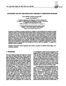
We have investigated the application of the UML for modeling IP-XACT compatible component and system descriptions. This paper describes the resulting UML-based IP description approach, which enables the comprehensible visual modeling of IP-XACT components and designs. The resulting models are still fully IP-XACT compatible in our approach because they contain the same information as an IP-XACT description. Thus, the UML models can serve directly as the basis for the automatic generation of equivalent IP-XACT descriptions driving a respective design flow as shown in Fig. 1.
UML IP-XACT Descriptions (Bus/AbstractionDefinitions, Components,Abstractors, Design) Transformation
XML IP-XACT Descriptions (Bus/AbstractionDefinitions, Components,Abstractors, Design)
Components and Abstractors SystemC Models
Code Generation
Makefile
Design SystemC Model
Compilation and Simulation
Fig. 1: SystemC design flow driven by UML IP-XACT descriptions
In the remainder of this paper, we first give a brief overview of IP-XACT and related works before we describe our UML IP-XACT profile and its application to an actual design example based on the IBM PowerPC Evaluation Kit. However, given the extent of the ground covered by IP-XACT and our respective UML profile, this paper cannot provide a complete description of all relevant aspects. Therefore, we focus on the basic concepts driving the approach and emphasize the visual modeling aspect, which provides the main benefits of our approach in contrast to the direct application of IP-XACT.
II.
BACKGROUND
The IP-XACT standard [10] defines an XML-based data format for IP description and integration. For this, it supports the description, configuration, and composition of IPs to actual system designs using a standardized, well-defined data format. This enables the creation of vendor-independent tools for automated IP-integration. IP-XACT defines four central elements, which are bus definition, abstraction definition, component, and design. A bus definition describes a bus, such as AHB or PLB, in terms of its most basic properties such as the supported number of masters and slaves. It basically serves as a reference for providing more detailed descriptions of the same bus at different levels of abstraction. An abstraction definition provides a complete description of the set of interfaces of a bus at a specific level of abstraction, e.g., TLM (Transaction Level Model). For this, all interfaces, such as the master and the slave interfaces, are described in terms of the respective ports. A port is a distinct interaction point on the bus, which may be a wire port carrying logic values, or a transactional port, typed by a high-level interface. The latter typically refers to a TLM port. A component packages an actual, potentially configurable, IP-core. It may contain multiple views at the core covering different aspects or levels of abstraction. In particular, a component describes the bus interfaces exposed by the core, and the mapping between component ports and the respective ports from the corresponding abstraction definition. In addition, model parameters that enable configuration of IP core itself can be defined, e.g., the actual width of a bus interface. A design describes an actual design as a set of interconnected component instances. These connections are usually made between bus interfaces, but component ports may also be connected directly (ad-hoc connections). Furthermore, the model parameters can be individually configured for each instance. If two components are connected through bus interfaces at different abstraction levels, e.g. one RTL and one TLM, an abstractor can be inserted between the two components to act as an interface adaptor. Finally, the Tight Generator Interface (TGI) enables external tools to perform operations related to an IP-XACT specification such as configuration or model generation. For this, it defines a comprehensive set of SOAP methods for retrieving and modifying all information in a SPIRIT XML file. It is required to be implemented by any IP-XACTconformant design tool. III.
RELATED WORK
There already exist some approaches discussing the relation between IP-XACT and the UML. Unfortunately, they provide only limited coverage of the current IP-XACT 1.4 standard with its significant extensions compared to IP-XACT 1.2, or just sketch initial ideas.
In [4], an approach for UML-based modeling and code generation of HW/SW interfaces is presented. In this context, the authors consider leveraging the benefits of IP-XACT. This work focuses on functional aspects of IP modeling. Thus, the relation to IP-XACT is not further investigated. An initial alignment of the MARTE UML profile [2] with IP-XACT is presented in [3]. However, the approach is only sketched by an example. A similar approach can be found in [1], which maps the TUT UML profile for embedded system design to IP-XACT. The resulting IP-XACT design flow utilizing UML is also presented. It focuses on IP-XACT version 1.2, thus lacking the coverage of ESL (Electronic System Level) features. Finally, we already sketched some initial ideas of our approach in the context of the application example in [11]. Still, significant changes to these ideas were necessary to provide a generally applicable UML profile for IP-XACT, to increase usability of the visual notation, and to enable broad coverage of the IP-XACT standard that enables the application of the UML as a frontend for IP-XACT-based design flows. IV.
UML PROFILE FOR IP-XACT
To enable the consistent application of the UML and IPXACT, the UML models must provide the same information as a respective IP-XACT description. For this, we have mapped all IP-XACT concepts to corresponding UML concepts. This mapping is not straightforward as the UML represents some IPXACT concepts in a different, but it is consistent and often more intuitive. As an example, UML directly provides concepts such as subtyping, which IP-XACT reflects only through respective XML-attributes. A larger but more striking example is that IP-XACT scatters the ports for a master or slave around the standard document. Using our approach, the master and slave bus interfaces are explicitly modeled as a UML classifier containing all relevant ports. Furthermore, some of the concepts that are explicitly provided by IP-XACT, such as enabling the addition of descriptive text or vendor extensions, can be replicated directly using existing UML concepts, which in this case are UML notes and the profiling mechanism. Thus, such concepts are not explicitly reflected. «metaclass» Pack age
owningPackage
packagedElement
0..1
«extends»
*
name provided by UML's NamedElement.name
library «stereotype» IP-XACT_ Library 1
«metaclass» Pack ageableElement
«extends»
*
«stereotype» IP-XACT_ Identifier vendor: String [0..1] version: String
vendor is implied by containing library unless eplicitly given
Fig. 2: IP-XACT profile - libraries and versioned identifiers diagram
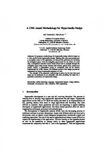
The versioned identifiers that underlie most elements of IPXACT are represented through IP-XACT_Identifier (see Fig. 2), which serves as the base type for all stereotypes describing the respective derived IP-XACT elements. One such element is the IP-XACT_Library, which is a specialized UML package for holding component and bus definitions. An IP-XACT bus definition is represented by a UML class as shown in Fig. 3. As defined in Fig. 4 and Fig. 5, a corresponding abstraction definition is represented by a specialized UML package containing specialized UML classes that define the actual master, slave, and system interfaces of the bus. These specialized IP-XACT_PortsDefinition classes provide the context for the definition of the respective IPXACT ports through specialized UML ports. This is in contrast to IP-XACT. The rationale for this difference is that we found the resulting notation much more comprehensible. «stereotype» IP-XACT_ Identifier
«metaclass» Por t
/ownedPort 0..1
*
«metaclass» Clas s «extends»
«extends» «invariant» {all ownedMembers of the extended Class must be IP-XACT_Ports}
«stereotype» IP-XACT_PortsDefinition
«stereotype» IP-XACT_ MasterDefinition
«stereotype» IP-XACT_BusDefinition
IP_XACT 's 'extends' attribute is mapped to single inheritance on IPXACT _BusDefinition Interfaces
isAddressable: Boolean maxMasters: UnlimitedNatural = * maxSlaves: UnlimitedNatural = *
«stereotype» IP-XACT_ DirectConnectionBus
«metaclass» EncapsulatedClassifie r
«stereotype» IP-XACT_Port
«metaclass» Clas s
«extends» IP-XACT's 'directConnection' attribute is implemented through the respective subclasses of this abstract model element
Fig. 8. The service direction and type are modeled as a required or provided UML interface on the respective IPXACT_TransactionalPort.
«stereotype» IP-XACT_ MirroredConnectionBus
«stereotype» IP-XACT_ Slav eDefinition
«stereotype» IP-XACT_SystemDefinition
Fig. 5: IP-XACT profile – port definition diagram
UML's NamedElement.name corresponds to the IPXACT 'logicalName' attribute
«stereotype» IP-XACT_Port displayName: String [0..1] isOptional: boolean = true
IP-XACT's 'presence' attribute maps to isOptional. Illegal Ports are just not defined in the respective PortsDefinition.
Fig. 3: IP-XACT profile - bus definition diagram «stereotype» IP-XACT_ TransactionalPort «stereotype» IP-XACT_ Identifier
«metaclass» Pack age
{XP-XACT busType must be indicated through an Abstraction Dependency to the corresponding IPXACT_BusDefinition}
«stereotype» IP-XACT_ Wire
Fig. 6: IP-XACT profile - port types diagram
«extends» «stereotype» IP-XACT_AbstractionDefinition
«stereotype» IP-XACT_ MasterDefinition 0..1
IP-XACT's 'qualifier' is implemented directly through the respective subtypes
«stereotype» IP-XACT_ Wire
«enumeration» IP-XACT_ Direction
width: int [0..1] direction: IP-XACT_Direction [0..1]
«stereotype» IP-XACT_ Slav eDefinition
«enum» in out inout
0..1 «stereotype» IP-XACT_SystemDefinition
«stereotype» IP-XACT_MixedWire
«stereotype» IP-XACT_ DataWire
«stereotype» IP-XACT_ AddressWire
*
Fig. 4: IP-XACT profile - abstraction definition diagram
The actual ports of an interface are modeled as specialized UML ports of the respective IP-XACT_PortsDefinition class. The actual types of these ports are modeled as descendents of the IP-XACT_Port stereotype as shown in Fig. 6, Fig. 7, and
«stereotype» IP-XACT_ ClockWire
«stereotype» IP-XACT_ ResetWire
Fig. 7: IP-XACT profile - wire ports diagram
Ports of a component are modeled as IP-XACT_ PhysicalPorts owned by the respective IP-XACT_Component as defined in Fig. 9. The IP-XACT model parameters correspond directly to specialized attributes of the respective IP-XACT_Component. The actual values for these attributes are given for each instance of the component in an actual design model. The bus interfaces of a component are modeled as UML_Ports typed over the respective IP-XACT_ PortsDefinition. Their connection scheme is indicated using a respective stereotype as defined in Fig. 10. Using a mirrored connection scheme for a bus interface has the semantics of flipping the direction of each port on the interface. This in particular means that provided interfaces become required interfaces and vice versa. This is important because consequently such an IP-XACT_BusInterface is no longer directly typed by the respective IPXACT_PortsDefinition. Instead, the actual type is implicitly derived from the ports definition.
The logical-to-physical port mapping for an IPXACT_BusInterface is performed by interconnecting the respective IP-XACT_PhysicalPorts of the component with the corresponding IP-XACT_Ports of the bus interface. It is important to note that the IP-XACT_BusInterface is by itself an UML port, which becomes the actual interaction point on the component for the bus. Thus, despite the fact that in the respective UML Composite Structure Diagram the component ports usually appear on the border to the outside, it is in fact the contained bus interface that forwards incoming requests to the component. Furthermore, such requests are duplicated if multiple bus interface instances are connected to the same component port. Finally, as defined in Fig. 11, an actual design is represented similar to a library using a specialized UML Package containing a valid instance of interconnected IPXACT_Components. This instance can be described using an instance level UML Composite Structure Diagram illustrating the interconnections of the ports and the actual values of for model parameters.
«stereotype» IP-XACT_Port «stereotype» IP-XACT_BusInterface
displayName: String [0..1] isOptional: boolean = true IP-XACT's 'initiative' is modeled through respective provided and required interfaces
connectionRequired: boolean = false
IP-XACT's 'service' attribute corresponds the Type of the Port «stereotype» IP-XACT_ TransactionalPort
IP-XACT's 'qualifier' attribute is implemented directly through the respective subtypes of IPXACT_TransactionalPort
Concrete Syntax: Port with T,TA,TD, or TM
isImplicit: boolean = false
«stereotype» IP-XACT_ TransactionalDataPort
«stereotype» IP-XACT_ TransactionalAddressPort
«stereotype» IP-XACT_TransactionalMix edPort
«stereotype» IP-XACT_ MasterBI
«stereotype» IP-XACT_ Slav eBI
«stereotype» IP-XACT_MirroredMasterBI
«stereotype» IP-XACT_SystemBI
«stereotype» IP-XACT_MirroredSlav eBI
«stereotype» IP-XACT_ MonitorBI
«stereotype» IP-XACT_MirroredSystemBI
Fig. 10: IP-XACT profile - bus interfaces diagram Fig. 8: IP-XACT profile - transactional ports «metaclass» Clas s
class
ownedAttribute
0..1
* {subset s ownedMember}
«metaclass» Pack age
«metaclass» Property
«stereotype» IP-XACT_ Identifier
«extends» «stereotype» IP-XACT_ Design
«metaclass» Por t «stereotype» IP-XACT_ Identifier
«extends» «stereotype» IP-XACT_ Component
«extends»
«stereotype» IP-XACT_BusInterface
«invariant» {all ownedMembers of the extended Class must be IP-XACT_ModelParameters or IP-XACT_Businterfaces}
«extends»
«extends»
«stereotype» IP-XACT_PhysicalPort
«invariant» {all ownedMembers of the Classifier (implicitly) typing the extended Port must be IP-XACT_PhysicalPorts}
Fig. 9: IP-XACT profile - components diagram
«stereotype» IP-XACT_ ModelParameter
«invariant» {the extended Port must be directly owned by a Port extended by IP-XACT_BusInterface}
Fig. 11: IP-XACT profile - design diagram
V.
CORECONNECT EXAMPLE
For further illustration, we describe how the UML IPXACT profile is employed to model individual IPs and their integration in actual designs. For this, we present a basic master/slave design around the CoreConnect Processor Local Bus (PLB). The example is based on CoreConnect TLM
components from the IBM PowerPC 405 Evaluation Kit (PEK) [5]. A. Library Definition In our approach, an IP-XACT library is mapped directly to a corresponding UML package containing all bus and component definitions of the library. Fig. 12 shows the contents of the TLM CoreConnect library as discussed in this example. The bus and abstraction definitions for the PLB are given in Fig. 13. The UML package representing the abstraction definition contains classes defining the actual bus interfaces for PLB masters and slaves in terms of their ports. In this example, we note that each of these interfaces hosts a single port providing or requiring one transactional interface. The width of data and address busses of the CoreConnect architecture is configurable for each components. Thus, we decided to introduce a common base type for all respective CoreConnectComponents that host the respective model parameters (see Fig. 14). The actual components such as the PLB_BUS are now modeled as descendents of this base type.
The actual PLB_BUS component with master and slave bus interfaces is defined by the Composite Structure Diagram shown in Fig. 15. This diagram also defines the port mapping between component and bus interface ports. We generally note that attribute values for attributes of the stereotype are – like in UML – either given directly as part of the compartment for tagged values or, in the case of boolean meta attributes, also as respective constraints like for connectionRequired. Finally, the definitions of the generic PLB master and slave components are given in Fig. 16 and Fig. 17. Both definitions are quite similar and introduce additional model parameters for these components. «IP-XACT_Component» CoreConnectComponent «IP-XACT_ModelParameter» DATA_BUS_WIDTH: CC_BusWidth = CC_ 128 ADDRESS_BUS_WIDTH: CC_BusWidth = CC_ 64
Fig. 14: Definition of the basic (abstract) parameterizable CoreConnect component CoreConnectComponent «IP-XACT_Component» PLB_ BUS
«IP-XACT_Library» CoreConnectTLM + CoreConnectComponent
tags version = '2.0'
+ PLB_BUS + PLB_BusDef
«IP-XACT_MirroredMasterBI»
+ plb_master_generic
master :PLB_Master
+ plb_slave_generic + PLB_AbsDef
constraints {connectionRequired}
tags vendor = 'ibm.com' version = '2.0'
PLB_Master_port T
plb_bus_if T PLB_BUS_ IF
«IP-XACT_MirroredSlaveBI» slav e1 :PLB_Slave
Fig. 12: Package defining the contents of the CoreConnect TLM library
PLB_Slave_port T
«IP-XACT_MirroredSlaveBI»
slave_port T PLB_SLAVE_ IF
slav e2 :PLB_Slave PLB_Slave_port T
«IP-XACT_MirroredConnectionBus» PLB_ BusDef tags isAddressable = false version = '2.0'
Fig. 15: Definition of the generic PLB bus component CoreConnectComponent
«abstraction»
«IP-XACT_Component» plb_master_generic
«IP-XACT_AbstractionDefinition» PLB_AbsDef
«IP-XACT_ModelParameter» MASTER_ID: int = 0 tags
tags
version = '2.0'
version = '2.0'
«IP-XACT_MasterDefinition» PLB_Master
«IP-XACT_SlaveDefinition» PLB_Slave
PLB_Master_port T
T PLB_Slave_port PLB_BUS_ IF
«IP-XACT_MasterBI» plb_master :PLB_Master
PLB_SLAVE_ IF
constraints {connectionRequired}
Fig. 13: Bus definition and TLM abstraction definition for the Processor Local Bus (PLB)
PLB_Master_port T
bus T
Fig. 16: Definition of the generic PLB master component
PLB_BUS_ IF
their integration in an intuitive manner. The application of this profile has been illustrated by components from the IBM PowerPC Evaluation Kit. We have also shown that resulting models cover the same information as a corresponding IPXACT description. Consequently, such descriptions can be automatically generated and serve as the input to IP-XACT based tools in the ESL design flow.
CoreConnectComponent «IP-XACT_Component» plb_slav e_generic «IP-XACT_ModelParameter» ADDRESS_LOW: int = 0x00000 ADDRESS_HIGH: int = 0x1ffff tags version = '2.0' «IP-XACT_SlaveBI» plb_slave :PLB_Slave
constraints {connectionRequired} PLB_Slave_port T
plb_slave_if T PLB_SLAVE_ IF
Fig. 17: Definition of the generic PLB slave component
Future work will cover the evaluation of our approach in large scenarios and different design flows. Furthermore, we are working on an alignment with other ongoing work in UMLbased SoC modeling and currently apply parts of the profile for SysML tool configurations in the context of SystemC-based modeling and code generation in the SATURN project with ARTiSAN Studio.
ACKNOWLEDGMENT B. Design Example A simple design based on the introduced components is shown in Fig. 18. This particular design corresponds to a PLB bus with a single master and two slaves, which is represented by instances of the respective IP-XACT_Components. Instances are interconnected based on their BusInterfaces, which now serve as ports with provided and required interfaces.
The work described herein is supported by the FP6 project SPRINT - Open SoC Design Platform for Reuse and INTegration of IPs (IST-2004-027580) and the FP7 project SATURN - SyML bAsed modeling, architecTUre exploRation, simulation and syNthesis for complex embedded systems (FP7216807).
REFERENCES «IP-XACT_Design» PLB Master w ith tw o Slav es
[1] tags
vendor = 'C-LAB' version = '1.0'
«IP-XACT_Component» plb :PLB_BUS DATA_BUS_WIDTH = CC_128 ADDRESS_BUS_WIDTH = CC_64
«IP-XACT_Component» cpu :plb_master_generic DATA_BUS_WIDTH = CC_128 plb_master M ADDRESS_BUS_WIDTH = CC_64
|M master
«IP-XACT_Component» slav e1 :plb_slav e_generic DATA_BUS_WIDTH = CC_128 ADDRESS_BUS_WIDTH = CC_64 ADDRESS_LOW = 0x00000 ADDRESS_HIGH = 0x0ffff
plb_slave S
|S slave1
plb_slave S
|S slave2
«IP-XACT_Component» slav e2 :plb_slav e_generic DATA_BUS_WIDTH = CC_128 ADDRESS_BUS_WIDTH = CC_64 ADDRESS_LOW = 0x10000 ADDRESS_HIGH = 0x1ffff
Fig. 18: Sample design based on the PLB and the generic master and slave components
VI.
CONCLUSIONS AND FUTURE WORK
In this paper, we have shown that the UML can be employed as a frontend for modeling IP-XACT-based IP description and integration. For this, we have presented a UML profile for IP-XACT, which enables comprehensive and fully IP-XACT-compatible visual modeling of IP-components and
Arpinen, T., Salminen, E., Hännikäinen, M., Hämäläinen, T. D.: ModelDriven Approach for Automatic SPIRIT IP Integration. In: Proc. 5th Int. UML-SoC DAC Workshop, Anaheim, USA, 2008. [2] André, C., Cuccuru, S., Dekeyser, J.-L., De Simone, R., Dumoulin, C., Forget, J., Goutier, T., Gérard, S., Mallet, F., Radermachenr, A., Rioux, L., Shaunier, T, Sorel, Y.: MARTE: A New OMG Profile RFP for the Modeling and Analysis of Real-Time Embedded Systems. In: Proc. 2nd Int. UML-SoC DAC Workshop, Anaheim, USA, 2005. [3] Charles André, Frédéric Mallet, Aamir Mehmood Khan and Robert de Simone: Modeling SPIRIT IP-XACT with UML MARTE. In: Proc. DATE Workshop on Modeling and Analysis of Real-Time and Embedded Systems with the MARTE UML profile, 2008. [4] Ecker, Wolfgang, Esen, Volkan, Steininger, Thomas, Velten, Michael: UML based SW Generation for the HW/SW Interface. In: Proc. 5th Int. UML-SoC DAC Workshop, Anaheim, USA, 2008. [5] IBM: IBM PowerPC 405 Evaluation Kit with CoreConnect SystemC TLMs. Available at www.ibm.com/developer works/ power/pek/, 2006. [6] Magillem Design Services: Magillem tool suite home page. Avaialble at www.magillem.com/, 2008. [7] Martin, Grant, Müller, Wolfgang (eds): UML for SOC Design. Springer Verlag, Heidelberg, 2005. [8] Object Management Group: UML Profile for System on a Chip (SoC). OMG formal/06-08-01, 2006. [9] Object Management Group: Unified Modeling Language: Superstructure, V 2.1.2. OMG ad/2007-11-01, 2007. [10] SPIRIT Consortium: IP-XACT v1.4: A specification for XML meta-data and tool interfaces. Available at www.spiritconsortium.org, 2008. [11] Schattkowsky, Tim, Xie, Tao: UML and IP-XACT for Integrated SPRINT IP Management. In: Proc. 5th Int. UML-SoC DAC Workshop, Anaheim, USA, 2008.