that supports the plastic development of user interfaces. The framework as ... These requirements induce extra cost in development and maintenance, and complicate ...... Interact99, Edinburgh, A. Sasse & C. Johnson Eds, IFIP IOS Press. Publ.
A Unifying Reference Framework for the Development of Plastic User Interfaces Gaëlle Calvary, Joëlle Coutaz, and David Thevenin CLIPS-IMAG, BP 53, 38041 Grenoble Cedex 9, France {Joelle.Coutaz, Gaelle.Calvary, David.Thevenin}@imag.fr
Abstract. The increasing proliferation of computational devices has introduced the need for applications to run on multiple platforms in different physical environments. Providing a user interface specially crafted for each context of use is extremely costly and may result in inconsistent behavior. User interfaces must now be capable of adapting to multiple sources of variation. This paper presents a unifying framework that structures the development process of plastic user interfaces. A plastic user interface is capable of adapting to variations of the context of use while preserving usability. The reference framework has guided the design of ARTStudio, a model-based tool that supports the plastic development of user interfaces. The framework as well as ARTStudio are illustrated with a common running example: a home heating control system.
1 Introduction Recent years have seen the introduction of many types of computers and devices. In order to perform their tasks, people now have available a wide variety of computational devices ranging over cellular telephones, personal digital assistants (PDA’s), Internet enabled televisions (WebTV) and electronic whiteboards powered by high end desktop machines. While the increasing proliferation of fixed and mobile devices fits with the need for ubiquitous access to information processing, this diversity offers new challenges to the HCI software community. These include: − constructing and maintaining versions of single applications across multiple devices; − checking consistency between versions for guaranteeing a seamless interaction across multiple devices; − building into these versions the ability to dynamically respond to changes in the environment such as network connectivity, user’s location, ambient sound or lighting conditions. These requirements induce extra cost in development and maintenance, and complicate the configuration management. In [20], we presented a first attempt at optimising the development process of user interfaces using the notion of plasticity as a foundational
property. Plasticity refers to the ability of a user interface to mould itself to a range of computational devices and environments, both statically and/or dynamically, whether it be automatically or with human intervention. In this paper, we go one step further with the presentation of a reference framework for supporting the structured development of plastic user interfaces. In the following section, we present the EDF home heating control system as our running example to illustrate the concepts and principles of the framework. We then recall the definition of our notion of plasticity before describing the framework and ARTStudio, a tool that supports the development of plastic user interfaces.
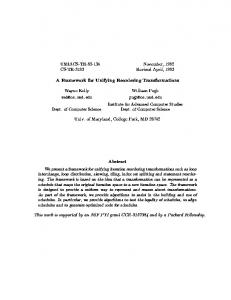
2 An example: the EDF Home Heating Control System The heating control system envisioned by EDF (the French Electricity Company) will be controlled by users situated in diverse contexts of use. These include: − At home, through a dedicated wall-mounted device or through a PDA connected to a wireless home-net; − In the office, through the Web, using a standard work station; − Anywhere using a WAP-enabled mobile phone. A typical user's task consists of consulting and modifying the temperature of a particular room. Figures 1 and 2 show versions of the system for different computational devices: − In 1 a), the system displays the current temperature for each of the rooms of the house (the bedroom, the bathroom, and the living room). The screen size is comfortable enough to make observable the entire system state; − In 1 b), the system shows the temperature of a single room at a time. A thumbnail allows users to switch between rooms. In contrast with 1a), the system state is not observable, but browsable [10]: additional navigational tasks, e.g., selecting the appropriate room, must be performed to reach the desired information.
(a)
(b)
Fig. 1. a) Large screen. The temperature of the rooms are available at a glance. b) Small screen. The temperature of a single room is displayed at a time.
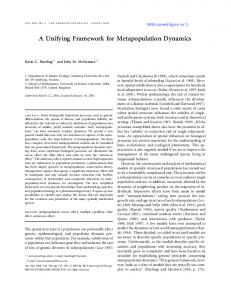
Figure 2 shows the interaction trajectory for setting the temperature of a room with a WAP-enabled mobile phone. − In 2a), the user selects the room (e.g., "le salon" – the living room). − In 2b), the system shows the current temperature of the living room. − By selecting the editing function ("donner ordre"), one can modify the temperature of the selected room (2c). When comparing with the situation depicted in Figure 1a), two navigation tasks (i.e., selecting the room, then selecting the edit function) must be performed in order to reach the desired state. In addition, a title has been added to every deck (i.e., a WML page) to recall the user with the current location within the interaction space.
(a)
(b)
(c)
Fig. 2. Modifying the temperature using a WAP-enabled mobile phone.
All of these alternatives have been produced using our reference framework devised for supporting plasticity.
3 Plasticity and related concepts The term plasticity is inspired from the property of materials that expand and contract under natural constraints without breaking, thus preserving continuous usage. Applied to HCI, plasticity is the "capacity of an interactive system to withstand variations of context of use while preserving usability". In the following subsections, we successively develop the key elements of our definition: context of use, usability, and the process for adapting to changes. 3.1
Plasticity and Context of Use
A context of use for a plastic user interface is defined by two classes of physical entities: − The physical and software platform(s), that is, the computational device(s) used for interacting with the system. − The physical environment where the interaction takes place. A platform is modeled in terms of resources which, in turn, determine the way information is computed, transmitted, rendered, and manipulated by users. Typically, memory size, network bandwidth and interactional devices motivate the choice for a set of input and output modalities and, for each modality, the amount of information made available. For example, screen size is a determining factor in the design of the EDF Heating Control System.
An environment covers "the set of objects, persons and events that are peripheral to the current task(s) but that may have an impact on the system and/or the user's behavior, either now or in the future". According to this definition, an environment may encompass the entire world. In practice, the boundary is set up by domain analysts whose role is to elicit the entities that are relevant to the case at hand. These include observation of users' practice [2, 5] as well as consideration for technical constraints. For example, surrounding noise should be considered in relation to sonic feedback. Lighting condition is an issue when it may influence the robustness of a computer vision-based tracking system. User's location provides context for information relevance: Tasks that are central in the office (e.g., writing a paper) may become secondary, or even irrelevant, in a train. For example, programming the EDF heating system is available on the central wall-mounted device only: according to the domain analysts, this task would not make sense, or would be too complex to be performed with current telephone technology. In summary, − a context of use, which consists of the association of a platform with an environment, is definitely anchored in the physical world. Therefore, it does not cover the user's mental models; − plasticity is not only about condensing and expanding information according to the context of use. It also covers the contraction and expansion of the set of tasks in order to preserve usability. 3.2
Plasticity and Usability
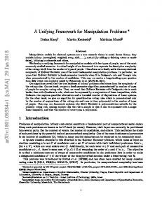
The quality of an interactive system is evaluated against a set of properties selected in the early phases of the development process. "A plastic user interface preserves usability if the properties elicited at the design stage are kept within a predefined range of values as adaptation occurs to different contexts of use". Although the properties developed so far in HCI [10] provide a sound basis for characterizing usability, they do not cover all aspects of plasticity. We propose additional metrics for evaluating the plasticity of user interfaces. Figure 3 makes explicit the association of a platform with an environment to define a context of use. We suppose that platforms and environments can be ranked against some criteria computed from their attributes. For example, screen size, computational power and communication bandwidth, are typical attributes of a platform. Using these attributes, a PC would be ranked lower than a PDA since it imposes less constraints on the user interface. Similarly an environment with no noise would be ranked lower than the open street. Then: − the plasticity of a user interface can be characterised by the sets of contexts it is able to accommodate, − contexts at the boundaries of a set define the plasticity threshold of the user interface for this set,
− the sum of the surfaces covered by each set, or the sum of the cardinality of each set, defines an overall objective quantitative metrics for plasticity. In other word, this sum can be used to compare solutions to plasticity: A user interface U1 is more plastic than a user interface U2 if the cardinality of the set of contexts covered by U1 is greater than that of U2. We suggest additional metrics to refine the overall measure of plasticity in relation to discontinuity [9]. These include: − The size of the largest surface: large surfaces denote a wide spectrum of adaptation without technical rupture. − The number of distinct sets: a large number of sets reveals multiple sources for technical discontinuities. Are these discontinuities compatible with user's expectation? Typically, GSM does not work everywhere. This situation translates as a discontinuity when moving along the environment axis of figure 3. The solution developed for EDF works for the Palm and the mobile phone, but not for the Psion. In this case, there is a discontinuity when moving along the platform axis. − Surface shapes: a convex surface denotes a comfortable continuous space (cf. Figure 3a). Conversely, concave curvatures may raise important design issues (cf. Figure 3b). Typically, ring shape surfaces indicate that the interior of the ring is not covered by the user interface. It expresses a technical discontinuity for contexts that are contiguous in the ranking scheme. Is this inconsistency, a problem from the user's perspective? A hole within a surface depicts the case where the user interface is nearly plastic over both sets of contexts, but not quite. Is this "tiny" rupture in context coverage expected by the target users? Environment
(b)
Plasticity thresholds
(a) (c)
Platform : Contexts
: Coverage of contexts
Fig. 3 . Measuring plasticity from the system's perspective. Greyed areas represent the sets of contexts that a particular technical solution covers. Environments and platforms are ranked against the level of constraints they impose on the user interface.
Intuitively, from a technical point of view, a large unique convex surface characterises a "good" plastic user interface whereas a large number of small concave surfaces de-
notes a large number of technical discontinuities. Although size, shape, cardinality, and topology of surfaces, are useful indicators for reasoning about the plasticity of a particular technical solution, we need to consider a complementary perspective: that of users. To this end, we suggest two indicators: context frequency and migration cost between contexts. − Context frequency expresses how often users will perform their tasks in a given context. Clearly, if the largest surfaces correspond to the less frequent contexts and/or if a multitude of small surfaces is related to frequent contexts, then designers should revise their technical solution space: the solution offers too much potential for interactional ruptures in the interactional process. − Migration cost measures the physical, cognitive and conative efforts [6] users have to pay when migrating between contexts, whether these contexts belong to the same or different surfaces (cf. Figure 4). Although this metrics is difficult to grasp precisely, the notion is important to consider even in a rough way as informal questions. For example, do users need (or expect) to move between contexts that belong to different surfaces? If so, discontinuity in system usage will be perceived. Designers may revise the solution space or, if they stick to their solution for wellmotivated reasons, the observability of the technical boundaries should be the focus of special attention in order to alleviate transitions costs. As plasticity threshold characterises the system capacity of continuous adaptation to multiple contexts, so migration cost threshold characterises the user's tolerance to context switching. The analysis of the relationships between the technical and the human thresholds may provide a useful additional perspective to the evaluation of plastic user interfaces. Context 2
Context 1 (i)
(j)
Context 3
: Migration cost from Context i to Context j
Fig. 4. Measuring plasticity from the human perspective. An arrow expresses the capacity of migrating between two contexts. Its thickness denotes human cost.
Having considered plasticity from the usability perspective, we need now to describe the process through which plastic adaptation may occur.
3.3
Plasticity and the adaptation process
As any evolutive phenomenon, plastic adaptation is structured as a five step process: − − − − −
detection of the conditions for adaptation (here, variations in the context of use), identification of candidate user interfaces appropriate to the new context of use, selection of a user interface, transition from the current user interface to the newly selected solution, execution of the new user interface until next conditions for adaptation occur.
Each of the five steps involved in the plasticity process (detection, identification, selection, transition, execution) is performed either by the system, or by the user, or as a mixture of both. At the two extremes, − The system is able to handle the five steps without human intervention. In this case, the system is capable of adaptative plasticity. − The user performs the five steps manually. The system supports adaptable plasticity. − Mixed plasticity covers a combination of both human and system intervention. Let's now consider the five steps of the adaptation process from a technical perspective. − System detection requires the capacity of sensing the physical environment as well as the capacity of modelling the physical platforms it is supposed to support. Our current implementation of the EDF heating control system includes a platform model. Although environmental conditions define the ontology of the system, these are not exploited yet at the user interface level. Conversely, the Hyperpalette [1], which allows users to "scoop and spread" information between PDA's and a computerised table, is able to detect conditions for compressing or expanding information layout, using an electromagnetic sensing tracker. On the other hand, the HyperPalette does not handle any explicit description of the computational platforms. − System identification of candidate solutions may be either computed on the fly, or selected from a pre-computed set of user interfaces, or from a predefined set of adhoc user interfaces. As discussed in Section 6, the EDF heating control system uses a pre-computed set of user interfaces. The Hyperpalette has available a predefined set of two ad-hoc user interfaces dedicated to a single platform (i.e., a PC or a PDA). − System selection of a particular solution relies on a problem solving strategy. The system may be assisted in this task by the user. − System transition between states has been analysed since the early developments of HCI. Norman's evaluation gap, Mackinlay's et al. use of graphical animation for transferring cognitive load to the perceptual level [17], the notion of visual discontinuity [10] etc., have all demonstrated the importance of transitions. Transition between the use of two user interfaces is therefore a crucial point that deserves spe-
cific research. The sources of discontinuities identified in Section 3 should provide a sound starting point. − System execution of the newly selected user interface may be launched from scratch or may preserve the system state. For example, the MacOS Location Manager supports switching to a different network protocol without interrupting the running applications. (On the other hand, the detection of the new context of use, as well as the selection step, are performed by the user). Preserving system state, which alleviates discontinuities, requires specific technical mechanisms. Adaptation performed by
the System
the Human &System
the Human
Adaptative Adaptative Half-plasticity Half-plasticity Research on Resource Research on Context sensitive UI sensitive UI
Adaptative Full-plasticity
Mixed Half-plasticity
Mixed Half-plasticity
Mixed Full-plasticity
Adaptable Half-plasticity
Adaptable Half-plasticity
Adaptable Full-plasticity
Platform
Environment
Adaptation to Platform&Environment
Fig. 5. A classification space for plastic user interfaces. Lines indicate the authors of the adaptation (system only, human only, both). Columns correspond to the coverage of the adaptation (platform only, environment only, both). Mixed plasticity may in turn be analysed according to the steps the system covers in the adaptation process.
Whether it be adaptative, adaptable or mixed, plasticity covers adaptation to both physical environments and platforms. In current main stream research on adaptation, the focus is either on environmental changes, or on platforms. Context-sensitive systems [18] address environmental conditions whereas resource-sensitive systems [11] exemplified by the development of XML-based standards, address adaptation to computational devices. Although adaptative, these systems and mechanisms demonstrate half-plasticity. The framework presented next is intended to cover all sorts of plasticity: half-full, adaptative-adaptable-mixed (see figure 5 for a simplified classification space).
4 A Reference Framework for Plasticity Our framework is intended to serve as a reference instrument to help designers and developers to structure the development process of plastic interactive systems. We adopt a model-based approach [16] similar to [7]. Modelling techniques support sound design methods (e.g., MAD[8], ADEPT[12,13], MUSE [14]) and pave the way to the development of appropriate tools such as Trident [21] and Mastermind [19]. As shown in Figure 6, the framework: − builds upon known models such as the domain concepts model and the tasks model, but improves them to accommodate variations of contexts of use; − explicitly introduces new models and heuristics that have been overlooked or ignored so far to convey contexts of use: the platform, the interactors, the environment and the evolution models. Context 1
Concep ts
Context 2 Task-oriented specification
Task-oriented specification
Abstract
Abstract
Interface
Interface
Concrete
Concrete
Interface
Interface
Tasks Platform
Tasks
Environment
Interactors
Platform
Environment
Evolution
Interactors
Evolution Running system System in Con For Context1
: Reification
Concepts
: Translation
Running system System in Con For Context2
Human Intervention
: Reference
Fig. 6 . The reference development process for supporting plastic user interfaces. The picture shows the process when applied to two distinct contexts: context1 and context2. Grayed boxes denote initial models.
The Concepts model describes the concepts that the user manipulates in any context of use. When considering plasticity issues, the domain model should cover all the contexts of use envisioned for the interactive system. By doing so, designers obtain a
global reusable reference model that can be specialised according to the sets of contexts discussed in Section 3. A similar design rationale holds for task modelling. The Platform Model and the Environment Model define the contexts of use intended by the designers based on the reasoning developed in Section 3. The Evolution model specifies the change of state within a context as well as the conditions for entering and leaving a particular context. The Interactors Model describes "resource sensitive multimodal widgets" available for producing the concrete interface. These models are specified by the developer. They are said initial models in contrast to transient and final models that are inferred by the developer and/or the system through the development process. A transient model is an intermediate model (e.g., the abstract and concrete user interfaces), necessary for the production of the final executable user interface. All of the above models are referenced along the development process from the task specification to the running interactive system. The process is a combination of vertical reification and horizontal translation. Vertical reification covers the derivation process, from top level abstract models to run time implementation. Horizontal derivations, such as those performed between HTML and WML content descriptions, correspond to translations between models at the same level of reification. Reification and translation may be performed automatically from specifications, or manually by human experts. Because automatic generation of user interfaces has not found wide acceptance in the past [15], our framework makes possible manual reifications and translations. Such operations are manual when the tools at hand cannot preserve the usability criteria discussed in Section 3. Automaticity, however, conveys interesting properties that may not be maintained when introducing manual operations within the development process: Let Reification ctxt (M) be the reification of model M in context ctxt, and Translation ctxt, ctxt' (M) be the translation of M from the source context ctxt to the target context ctxt', then: − Identity results from the combination of a translation with its inverse: ∀ ctxt, ctxt' Translation
ctxt, ctxt'
o Translation
ctxt', ctxt
=I
− Identity results from the combination of a reification and its inverse: ∀ ctxt Reification ctxt o Reification ctxt-1 = I − Reification and translation are commutative: ∀ ctxt, ctxt' Translation
ctxt, ctxt'
o Reification
ctxt'
= Reification ctxt o Translation
ctxt, ctxt'
(a) : Independant reifications
(b) : Reification before a final translation
(c) : Initial tran slation before reification
: Reification
(d) : Interleaving of reifications/translations
: Translation
: Reference
Fig. 7. Instantiations of the reference framework.
As shown in Figure 7, our reference framework can be instantiated in many ways: − In 7a), two running user interfaces are reified in parallel where the initial models are specified for each context of use. This configuration, which depicts current practice, forces to check and maintain consistency manually between the multiple versions. − 7b) corresponds to the ideal situation: reification is used until the very last step. Consistency maintenance is here minimal. This approach has been used for the Heating Control System shown in Figure 2 for Java-enabled target platforms. All of the interfaces shown in Figure 2 have been derived automatically using ARTStudio presented in Section 6. − In 7c), the task-oriented specification is translated to fit another context. From there, reifications are performed in parallel. This approach has been adopted for the Heating Control System for WAP mobile phones. Sub trees that correspond to infrequent tasks have been pruned from the original task tree developed for the Javaenabled platforms. Because ARTStudio does not support Web-based techniques yet, the reification steps have been done manually by a human expert. − 7d) shows a mix of interleaving between reification and translation.
5 ARTStudio ARTStudio (Adaptation by Reification and Translation) is a tool designed to support the reference framework for plasticity. We first discuss its actual implementation in relation to the framework then describe how a designer should proceed to produce a plastic user interface such as the EDF heating control system. 5.1
ARTStudio and the Plasticity Reference Framework
As shown in Figure 8, the current implementation of ARTStudio addresses the reification process only, and does not include the environment and the evolution models. According to the reference framework, the concepts and the task models serve the taskoriented specification which, in turn, leads to the automatic generation of the abstract user interface. Then, the platform model and the interactors model come into play for the automatic generation of the concrete user interface. Each of the transient models (i.e., Task-oriented specification, Abstract and Concrete User Interfaces) may be tuned by the designer to override the "defaults" options used by ARTStudio. Technically, ARTStudio is implemented in Java and uses the CLIPS rule-based language for generating the concrete user interface. Initial models as well as transient models are saved as XML files. So far, final executable user interfaces are expressed in Java. As a result, the current version of ARTStudio does not support XML-based executables. Concepts
Task-Oriented Specification
Tasks Platform
Abstract User Interf ace
Environment Concrete User Interactors Evolution
Interface
PlatformSpecific Application
Fig. 8. The actual functional coverage of ARTStudio in relation to the plasticity reference framework: translation as well as the environment and evolution models are not currently supported. The "human" symbol denotes the capacity for the designer to tune transient models.
5.2 ARTStudio and the development of a plastic user interface We first present an overview of the use of ARTStudio then discuss the models it supports. Overview. Within ARTStudio, the development of a plastic user interface forms a project (see Fig. 9). In the current implementation, a project includes the task and the concepts model, the context model and the abstract, the concrete and the executable user interfaces. By clicking on the "Contexte" thumbnail of Figure 9, the developer has access to the platform and interactors models. The "règles" thumbnail gives access to the generation rules used by ARTStudio during the reification process. These rules, which address presentation issues, can be adapted by the designer to the case at hand. In the current implementation, the rules are not editable. Let's now discuss the process and the associated models for producing a plastic user interface.
Fig. 9. In ARTStudio, a plastic user interface is developed within a project. The frame of the left end-side gives access to the sets of models. The picture shows the task model for a simplified version of the EDF Heating Control System.
The Task Model. An ARTStudio task model is a ConcurrTaskTree [3] structure where: − The leaves correspond to interaction tasks such as reading, selecting, and specifying. As shown in Figure 9, tasks Bedroom, Bathroom, Living room, and Rythm, respectively correspond to the specification of the level of comfort for the bed room, the bath room, the living room, and the rythm of living. The rythm of living expresses the default setting of room temperature based on periods of presence at home.
− The nodes, denoted by a "cloud" symbol, are abstract tasks. They structure the interaction space into sets of logically connected tasks. As such, abstract tasks offer a sound basis for the generation of the abstract user interface. In Figure 9, which shows a simplified version of the EDF Heating Control System, Prog groups together the tasks that permit the user to override the default temperature of the rooms. The task rythm, which has a specific status in the tasks space, is separated from the "overriding" tasks. − The vertices express temporal and logical relationships between tasks. For example, in Figure 9, all of the tasks can be performed in an interleaved way (Cf. symbol ///). The ARTStudio task editor allows the designer to add, cut and paste tasks by direct manipulation. As shown in Figure 10, additional parameters are specified through form filling. These include: − Specifying the name and the type of a task. For interaction tasks, the designer has to choose among a predefined set of "universal" interaction tasks such as "selection", "specification", "activation". This set may be extended to fit the work domain (e.g., "Switching to out of frost"). − Specifying a prologue and an epilogue, that is, providing function names whose execution will be launched before and after the execution of the task. At run time, these functions serve as gateways between the Dialogue Controller and the Functional Core Adaptor [10] of the interactive system. For example, for the task "setting the temperature of the bedroom", a prologue function is used to get the current value of the room temperature from the functional core. An epilogue function is specified to notify the functional core of the temperature change. − Referencing the concepts involved in the task and ranking them according to their level of importance in the task. This ordering is useful for the generation of the abstract and concrete user interfaces: typically, first class objects should be observable whereas second class objects may be browsable if observability cannot be guaranteed due to the lack of physical resources.
Fig. 10. Task specification through form filling.
The Concepts Model. Concepts are modeled as UML objects using form fill in. In addition to the standard UML specification, a concept description includes the specification by extension of its domain of values. For example, the value of the attribute name of type string of the room concept may be one among Living room, Bed room, etc. The type and the domain of values of a concept are useful information for identifying the candidate interactors involved in the concrete user interface. In our case of interest, the room concept may be represented as a set of strings (as in Figure 1a), as a thumbnail (as in Figure 1b), or as dedicated icons. The Abstract User Interface. The abstract user interface is modeled as a structured set of workspaces isomorphic to the task model: there is a one-to-one correspondence between a workspace and a task. In addition, a workspace that corresponds to an abstract task includes the workspaces that correspond to the subtasks of the abstract task: it is a compound workspace. Conversely, a leaf workspace is elementary. For example, Figure 11 shows three elementary workspaces (i.e., the Bedroom, the Bathroom and the Living Room) encapsulated in a common compound workspace. This parent workspace results from the Prog task of the task model. In turn, this workspace as well as the Rythm elementary workspace, are parts of the top level workspace.
1 compound workspace
3 elementary workspaces
Fig. 1 1 . The Abstract User Interface generated by ARTStudio from the Task Model of Figure 9. Thick line rectangles represent compound workspaces whereas thin line rectangles correspond to elementary workspaces.
By direct manipulation, the designer can reconfigure the default arrangements shown in Figure 11. For example, given the task model shown on the top of figure 12, the designer may decide to group the Rythm workspace with the Room workspaces (Figure 12 a) or, at the other extreme, suppress the intermediate structuring compound workspace (Figure 12 b). Rhythm ||| Bedroom
(a)
Bathroom Living room ||| |||
(b)
Fig. 1 2 . ARTStudio allows the designer to reconfigure the relationships between workspaces.
ARTStudio completes the workspace structure with a navigation scheme based on the logical and temporal relationships between tasks. The navigation scheme expresses the user's ability to migrate between workspaces at run time. The Platform Model. The platform model is a UML description that captures the following characteristics: − The size and the depth of the screen, − The programming language supported by the platform (e.g., Java). In its present form, the platform model is very primitive but is sufficient for demonstrating the key concepts of our reference framework. The Interactor Model. In [20] interactor modelling is discussed from a theoretical perspective in terms of representational capacity, interactional capacity and usage cost. In ARTStudio, our abstract interactor model boils down to the following simplified technical solution: − Representational capacity: an interactor can either serve as a mechanism for switching between workspaces (e.g., a button, a thumbnail), or be used to represent domain concepts (e.g., a multi-valued scale as in Figure 1). In the latter case, the interactor model includes the specification of the data type it is able to render. − Interactional capacity: the tasks that the interactor is able to support (e.g., specification, selection, navigation). − The usage cost, which measures the system resources as well as the human resources the interactor requires, is expressed as the "x,y" footprint of the interactor on a display screen and its proactivity or reactivity (i.e., whether it avoids users to make mistakes a priori or a posteriori [4]). The Concrete User Interface. As shown in Figure 8, the generation of the Concrete User Interface uses the Abstract User Interface, the platform and the interactors models, as well as heuristics. It consists of a set of mapping functions: − between workspaces and display surfaces such as windows and canvases, − between concepts and interactors, − between the navigation scheme and navigation interactors. The root workspace of the Abstract User Interface is mapped as a window. Any other workspace is mapped either as a window or as a canvas depending on the navigation interactor used for entering this workspace. Typically, a button navigation interactor opens a new window whereas a thumbnail leads to a new canvas. Mapping concepts to interactors is based on a constraint resolution system. For each of the concepts, ARTStudio matches the type and the domain of valuesof the concepts with the interactors representational capacity, the interactors interactional capacity and their usage cost.
Figure 13 shows the Concrete User Interfaces that correspond to the running user interfaces shown in Figure 1. Fig. 13a) targets large screens (e.g., Mac and PC workstations) whereas Fig. 13b) targets small screens (e.g., PDAs). (a)
(b)
Fig. 13. In a), the concrete user interface generated for the system when running on the large screen display of Figure 1a. In b), the concrete user interface that corresponds t o Figure 1b for the Palm Pilot.
As for the Abstract User Interface, the Concrete User Interface generated by ARTStudio is editable by the designer. The layout arrangement of the interactors can be modified by direct manipulation. In addition, the designer can override the default navigation scheme.
6 Conclusion Although the prospective development of interactive systems may be fun and valuable in the short run, we consider that the principles and theories developed for the desktop computer should not be put aside. Instead, our reply to the technological push is to use current knowledge as a sound basis, question current results, improve them, and invent new principles if necessary. This is the approach we have adopted for supporting plasticity by considering model-based techniques from the start. These techniques have been revised and extended to comply with a structuring reference framework. ARTStudio, a tool under development, provides a concrete, although incomplete, application of the framework. Plasticity is a complex problem. This article makes explicit our first steps towards a systematic high quality development of plastic user interfaces.
Acknowledment This work is being supported by EDF, France. We are very grateful to Nicholas Graham for the intensive discussions held in Grenoble about the notion of plasticity.
References 1. Ayatsuka, Y., Matsushita, N. Rekimoto, J.: Hyperpalette: a hybrid Computing Environment for Small Computing Devices. In: CHI2000 Extended Abstracts, ACM Publ. (2000) 53–53 2. Beyer, H., Holtzblatt K.: Contextual Design, Morgan Kaufmann Publ. (1998) 3. Breedvelt-Schouten, I.M., Paterno, F.D., Severijns, C.A.: Reusable structure in task models. In: Proceedings of DSVIS'97, Design, Specification and Verification of Interactive System, Horrison, M.D., Torres, J.C. (Eds) (1997), 225–240 4. Calvary, G.: Proactivité et réactivité: de l’Assignation à la Complémentarité en Conception et Evaluation d’Interfaces Homme-Machine, Phd of the University Joseph-FourierGrenoble I, Speciality Computer Science, (1998) 5. Cockton, G., Clarke S., Gray, P., Johnson, C.: Literate Development: Weaving Human Context into Design Specifications. In: Critical Issues in User Interface Engineering, P. Palanque & D. Benyon (Eds), Springer-Verlag: London Publ., ISBN 3-540-19964-0, (1995) 6. Dowell, J., Long, J.: Toward a conception for an engineering discipline of human factors, Ergonomics, Vol. 32 (11), (1989), 1513–1535
7. Eisenstein J., Vanderdonckt, J. Puerta, A.: Adapting to Mobile Contexts with UserInterfaec Modeling. In: Proc. of 3rd IEEE Workshop on Mobile Computing Systems and Applications WMCSA 2000 (Monterey, December 7-8, 2000), IEEE Press, Los Alamitos, (2000) 8. Gamboa,-Rodriguez, F., Scapin, D.: Editing MAD* Task Descriptions for Specifying User Interfaces at both Semantic and Presentation Levels. In: DSV-IS'97, Springer Computer Science, (1997), 193–208 9. Graham, T.C. N., Watts, L., Calvary, G., Coutaz, J., Dubois, E., Nigay, L.: A Dimension Space for the Design of Interactive Systems within their Physical Environments, DIS2000, ACM Publ. New York, (2000), 406–416 10. Gram, C., Cockton, G. Ed. : Design Principles for Interactive Software. Chapman & Hall, (1996) 11. HUC 2K, First workshop on Resource Sensitive Mobile Human-Computer Interaction, (2000) 12. Johnson, P. Wilson, S., Markopoulos, P., Pycock, Y.: ADEPT-Advanced Design Environment for Prototyping with Task Models. In: InterCHI’93 proceedings, (1993), 66 13. Johnson, P. Johnson, H. Wilson, S.: Rapid Prototyping of User Intefaces Driven b y Task Models, Scenario-based design: envisioning work and technology in system development, J. Carroll (ed.), John Wiley&Sons, (1995) 14. Lim, K. Y., Long, J.: The MUSE Method for Usability Engineering, Cambridge Univ. Press, (1994) 15. Myers, B., Hudson, S., Pausch, R.: Past, Present, Future of User Interface Tools. Transactions on Computer-Human Interaction, ACM, 7(1), March (2000), 3–28 16. Paternò, F.: Model-based Design and Evaluation of Interactive Applications, Springer Verlag, (1999) 17. Robertson, G., Mackinlay, J., Card, S.: Cone Trees: Animated 3D Visualizations of Hierarchical Information. In: Proc. CHI90, ACM Publ., (1991), 189–194 18. Salber, D., Dey, A. K., Abowd, G. D.: The Context Toolkit: Aiding the Development of Context-Enabled Applications. In: the Proceedings of the 1999 Conference on Human Factors in Computing Systems (CHI '99), Pittsburgh, PA, May 15–20, (1999), 434-441 19. Szekely P.: Retrospective and Challenges for Model-Based Interface Development, Computer-Aided Design of User Interfaces. In: Proceedings of CADUI'96, J. Vanderdonckt (eds), Presses Universitaires de Namur, (1996) 20. Thevenin, D., Coutaz, J.: Plasticity of User Interfaces: Framework and Research Agenda. In: Proc. Interact99, Edinburgh, A. Sasse & C. Johnson Eds, IFIP IOS Press Publ., (1999), 110–117 21. Vanderdonckt, J.: Knowledge-Based Systems for Automated User Interface Generation; The TRIDENT Experience. RP-95-010, Fac. Univ. de N-D de la Paix, Inst. d'Informatique, Namur, B, (1995)