A Variable Edge-Rate Compression Approach to Tunable Ultra-Wideband Pulse Generation E. Maxwell, T. Weller and J. Harrow-James A. Haley VAMC RF Microsystems Group, Department of Electrical Engineering, University of South Florida, Tampa, FL
[email protected] Abstract- The most recurrent pulse generator design approach described in literature employs a series step recovery diode (SRD) and pulse-duration tuning subsequent to Gaussian pulse formation. Although this conventional approach is advantageous in fixed pulse-duration designs, it leads to relatively complex designs for tunable generators. This paper presents a variable edge-rate compression (VERC) approach, to tunable ultrawideband generator design, that entails tuning prior to Gaussian pulse formation, and a shunt configuration of forward and reverse biased SRDs. Compared to the conventional approach, VERC offers performance advantages that include broader tuning range, improved tuning sensitivity, increased design simplicity and reduced cost. A comparison of the series and shunt SRD configurations reveals that input-signal slew rate has a dominant effect on pulse-duration tuning for an SRD in a shunt configuration. As slew rate may be modified using frequency, rise time or voltage, the VERC approach also offers greater design flexibility and is more advantageous for tunable UWB generator design.
continuous tuning range that is very narrow. Consequently, pulse-duration tuning for UWB generators has been accomplished by concatenating sections of transmission-line [9], [10]. A variable edge-rate compression (VERC) approach to tunable UWB generator design that entails pulse-duration tuning prior to Gaussian pulse formation and a shunt configuration of forward and reverse biased SRDs, is more advantageous for tunable generator design. In this paper, we compare the step-functions generated from series and shunt configurations, and demonstrate that VERC yields a broader tuning range, provides a highly responsive rise time, and establishes a practical design approach.
Index Terms - Pulse compression circuits, Pulse generation, Tunable circuits and devices, Ultra-Wideband.
I.
U
LTRA-WIDEBAND
INTRODUCTION
(UWB) radar systems have received increasing attention for numerous applications in communications, medicine and security [1]. The unique performance advantages offered by these systems, including improved measurement resolution and better clutter suppression, have compelled research toward resolving cost, performance, analysis and design challenges [2], [3]. One of the earliest and most persistent challenges has been pulse generation. A variety of techniques to generate the fast edgetransitions necessary to generate a UWB pulse have been used, including spark gaps, FETs, non-linear transmission lines and step recovery diodes (SRDs) [4], [5]. Of these techniques, SRDs stand out as a means to achieve a cost-effective and lownoise solution for developing generators with a fixed or variable pulse duration [6], [7]. UWB generators with a variable pulse-duration provide a valuable tool of research. They offer the possibility for dynamically modifying system electrical properties, including penetration depth, radiation intensity and range resolution. The most recurrent design approach for variable pulseduration generators employs a SRD in series with the input signal and tuning subsequent to Gaussian pulse formation [8]. This configuration is advantageous in fixed pulse-duration designs because the series circuit is simple and yields a stable waveform. However, this stable waveform gives rise to a
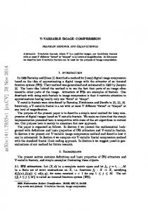
Figure 1. SRDs in a series (a) and shunt (b) configuration with power-supply.
II. METHODOLOGY A 14MHz adjustable-amplitude sine and square waveform has been used to excite a simple series (Fig. 1a) and shunt (Fig. 1b) circuit configuration to determine the step-function responsiveness. The sine waveform is used to evaluate the tuning range and sensitivity. Since, the adjustable-amplitude sine waveform composes two variables: voltage and slew-rate, a second waveform is used to determine which of these variables affects tuning. Consequently, a square waveform characterized by a constant slew rate and variable voltage is used to distinguish the optimization parameter from these variables. The analysis was performed using an Advanced Design System (ADS) 2003A simulation of Metelics SMMD840-SOT23-0S SRDs. In addition, a 20-80% rise time was used ensure measurement on the step-function regardless of the peak amplitude of the waveform. Finally, a simple tunable UWB step-function generator design demonstrates the practicality of a VERC approach by presenting a design in which tuning occurs prior to pulse formation. III. RESPONSIVE STEP FUNCTION A Gaussian pulse shape is desirable for UWB pulse generation because it minimizes overshoot and ringing.
tuning voltage varies from 20 to 1Vpp, the step-function voltage decreases so that at 1Vpp, it measures only 90mV. Consequently, in a series configuration, a lower signal-to-noise ratio increasingly challenges the utility of pulses with larger pulse durations. In contrast, the shunt configuration produces step-function amplitudes that decrease less rapidly as the tuning voltage decreases, so that at 1Vpp this amplitude measures 0.6V. The rise time associated with these waveforms range from .414.6nsec, which results in a wider FWHM pulse-duration tuning range from 0.84-30.5ns (see Fig. 2b). Even so, the morphological changes in the waveform of a shunt configuration are more profound over the 1-20Vpp tuning voltage. Voltage adjustments in the waveform generator tend to compress the rising and falling edges of the step function so that the waveform approximates a sinusoid at the lower limit and a square wave at the upper limit. Consequently, a shunt configuration provides a simpler means for producing a positive- or negative-going pulse with a broader tuning range and a step function that is not as easily perturbed by noise. Figure 2. ADS simulations showing voltage waveforms generated using a 1Vpp and 20Vpp 14MHz sources for a series (a) and shunt (b) connected SRD.
The original probability density function (PDF) introduced by Karl Gauss, is used to define this shape. When it is adapted for evaluation over rise-time it takes the following form: g ( t ,τ ∆V ) =
where
C =1
−2⋅
1
τ ∆V ⋅ 2π ⋅ C
(
⋅e
ln(V t ) − ln(V t −1
−
(t − 4⋅C ⋅τ ∆V )2
)
2⋅( C ⋅τ ∆V ) 2
,
(1)
and ∆V = Vt − Vt −1 .
In (1), τ∆V is the time required for a voltage transition over an interval ∆V, where Vt-1 and Vt are the signal amplitudes at times t-1 and t respectively for a normalized waveform [11]. The constant C defines the adjustment required to translate the standard deviation parameter in the original Gaussian PDF to rise time. This equation is important in developing an approach to tunable pulse generation, because it demonstrates that pulse rise time (τ∆V) can be used to describe Gaussian pulse morphology and relates to pulse-duration. The rise time and pulse duration (TpFWHM) at full-width-half-maximum (FWHM) are related as follows: TpFWHM ≈ 2.355 ⋅ C ⋅ τ ∆V .
(2)
Since the derivative of a step function is Gaussian, a tunable pulse is possible by altering the step-function rise time followed by differentiating the step. This approach reduces the complexity of UWB generator design by allowing pulseduration tuning to take place prior to Gaussian pulse formation. A. Tuning Range The series configuration demonstrates a 20-80% rise time ranging from .056-4.35nsec (see Fig. 2a). This corresponds to a FWHM pulse-duration tuning range of 0.12-9.1nsec. As the
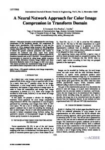
B. Tuning Sensitivity Pulse-duration tuning sensitivity is determined by measuring the effect that power-supply variations have on rise time. However, these variations also affect step-function voltage amplitude. The slew rate parameter concisely captures both of these properties. As such, a steeper slope in the slew rate indicates a narrower pulse-duration tuning range as well as a higher tuning sensitivity. As the voltage of the sine waveform is adjusted from 520Vpp, the series SRD configuration yields a step function with an increasingly negative peak-amplitude within a time of 30psec (see Fig. 3a). Since slew rate increases linearly, to a maximum of 70.721 V/nsec, the voltage sensitivity is approximately a constant of 0.2. Moreover, the rise-time sensitivity is low and increases from 3-16psec/V (see Fig. 3b). In contrast, the shunt configuration has a step-function rise time that increases symmetrically about zero (see Fig. 4a). It shows greater rise-time variation the slew rate varies nonlinearly to a maximum of 24.9V (see Fig. 4b). Consequently, step-function voltage sensitivity decreases over the 5-20Vpp interval, ranging from 0.213-0.062 and the rise-time sensitivity decreases markedly from 210-2psec/V. Consequently, the shunt configuration provides higher tuning sensitivity for longer-duration pulses and lower sensitivity for pulses with a shorter duration. This trend is more desirable because of it offers fine-tuning for short-duration pulses. C. Optimization Parameter Besides tuning sensitivity, it is useful to determine the optimization parameter that has a dominant affect on pulseduration tuning because it could lead to a simpler design. Although, common parameters include voltage and frequency, the frequency parameter is not always appropriate. An SRD step function responds to an input waveform characterized by
both bipolar-transient as well as periodic waveforms. Towards this end, slew rate is an indispensable parameter because it is applicable to any waveform type. Moreover, it relates to frequency through the following equation: sr =
∆V
τ ∆V
≈ 2.929 ⋅ f ⋅ V pp ,
(3)
where sr is slew rate, ∆V is voltage interval, Vpp is peak-topeak voltage and f is frequency [12]. Equation (3) demonstrates that at a given frequency, variations in powersupply voltage produce a sinusoid that has a variable slew rate but constant rise time. Consequently, two optimization parameters result from using a 14MHz sinusoidal source, which includes voltage and rise time. To distinguish the optimization parameter that affects pulse-duration tuning, the diodes are stimulated with another waveform in which the slew rate is constant. According to (3), a rise time adjustment is required to produce a constant slew rate at a fixed frequency. A square wave source presents an option to alter the slew rate independently of frequency. Thus, distinction of the optimization parameter is achieved using a 14MHz square wave with a constant 2V/nsec slew rate. In a series configuration, the square-wave input stimulates a rise-time tuning range that is nearly equivalent to that of a sinusoidal source (see Fig. 3b and Table I). Since the sinusoidal source provides slew rate and voltage as variables and slew rate is constant using the square wave, then amplitude is the origin of pulse-duration tuning. Conversely, in the proposed shunt configuration the rise-time tuning range decreases sharply when the slew rate is constant (see Fig. 4b and Table I). This change occurs because the origin of
Figure 4. ADS simulated (a) and calculated results of a series connected SRD with a 5, 7, 10, 15 and 20Vpp 14MHz sinusoidal source. (b) Calculated slew rate and 20-80% rise time versus the peak-to-peak voltage for a shunt diode.
pulse duration tuning for the shunt configuration is the slew rate parameter. These results support the argument that the proposed SRD shunt configuration is more desirable for tuning. The tuning effectiveness of amplitude adjustments in a series configuration is limited by the maximum allowable voltage amplitude. In contrast, in a shunt configuration, the slew rate may be altered by any combination of the rise time, frequency and voltage. Table I STEP-FUNCTION SLEW RATE AND RISE TIME AMPLITUDE (V) 1 5 10 20
SERIES CONFIGURATION Rise Time Slew Rate (nsec) (V/nsec) 0.40 0.14 0.07 26.2 0.06 57.2 0.03 159.6
SHUNT CONFIGURATION Rise Time Slew Rate (nsec) (V/nsec) 0.299 2.0 0.022 57.2 0.014 96.5 0.015 99.5
IV. SIMPLE APPROACH TO TUNABLE PULSE GENERATION The slew rate optimization parameter is of greatest importance in this experiment because it can be altered using many other input-signal properties to affect tuning, i.e. voltage, frequency, rise time or slew rate. Furthermore, slew rate variation can be achieved by varying the resistor-capacitor (RC) time constant of a circuit [16]. The goal of tuning prior to Gaussian pulse formation is established via the circuit below. Figure 3. ADS simulated (a) and calculated results of a series connected SRD with a 5, 7, 10, 15 and 20Vpp 14MHz sinusoidal source. (b) Calculated slew rate and 20-80% rise time versus the peak-to-peak voltage for a series connected diode.
A. Circuit Description and Design The schematic in Figure 5 shows a shunt configuration where the step function rise time is adjusted using a variable capacitor. Variable edge-rate compression provides a mechanism for producing a tunable pulse by allowing slew rate
control. This circuit is constructed using a Metelics SMMD840 SRD to rapidly charge up and snap back on the rising (SR1) and falling (SR2) edges of the source. Although a sharp falling edge is not typically used in the construction of a Gaussian waveform, the corresponding SRD (SR2) contributes to the pulse shape, width and low distortion achieved in this circuit. The edge rate is controlled using a simple RC network where RN is a 60Ω chip resistor and CN a capacitor trimmer with a 1-20pF range (Sprague-Goodman SG2020).
Figure 5. Schematic of the variable edge-rate compressor.
B. Fabrication and Measurement The variable edge rate compressor was fabricated on a Rogers Corporation high frequency laminate (RT5870) with a relative dielectric constant of 2.33 and a board thickness of 0.787mm. An Agilent 33120A arbitrary waveform generator was used to produce the 14MHz 10Vpp sinusoidal input stimulus and an HP 54750A digitizing oscilloscope with an HP54715A 20GHz module was used to capture the output waveform. All measured data obtained from this setup was compared to that simulated using ADS 2003A.
tuning range of the compressor as CN is varied from 1-20pF. The amplitude associated with the waveforms, in this figure, is a function of the amount of charge that is available from the SRDs at the time of the snap. Consequently, the voltage decreases with an increase in the circuit’s equivalent capacitance. Therefore, as the rise time increases the amplitude decreases. Moreover, good agreement between simulated and measured data is observed in Figure 6a,b. V. CONCLUSION We have demonstrated a novel approach to variable edgerate control for UWB pulse generation, by using SRDs in a shunt configuration.. This approach yields a broader continuous tuning range, provides a more responsive step function and a simpler design compared to the conventional approach. In addition, it offers more degrees of freedom for pulse-duration tuning, i.e. frequency, voltage and rise time adjustments. This approach also provides the option of positive- or negative-going pulses by differentiating either the rising or falling edge. Since a step-function derivative results in a Gaussian pulse, this approach creates a waveform that maintains its Gaussian appearance throughout the tuning range. In summary, we have described a new and improved UWB pulse-generation scheme that performs tuning prior to pulse formation, using forward- and reverse-biased recovery diodes in a shunt arrangement. REFERENCES [1]
Figure 6. ADS simulation (a) and measurement (b) results of the variable edgerate compression approach, for 1, 2, 5, 10 and 20pF capacitance values.
C. Discussion The simulation and measurement data were taken on the variable edge-rate-compressor. Figure 6a,b demonstrates the
R. Fontana, “Recent system applications of short-pulse ultra-wideband (UWB) Technology,” IEEE Trans. Microwave Theory Tech., vol. 52, no. 9, pp. 2087-2104, 2004. [2] Barrett, Terence W., “History of UltraWideBand (UWB) Radar & Communications: Pioneers and Innovators,” Proceedings of Progress in Electromagnetics Symposium 2000, Cambridge, MA, July 2000. [3] Engler, Harold F., “Technical Issues in Ultra-Wideband Radar Systems,” 0-8493-4440-9, CRC Press, Inc., pp 11-50, 1995. [4] Prather, William D., Baum, Carl E., Lehr, Jane M., et. al. Ultra-wideband source and antenna research, IEEE Transactions on Plasma Science Volume: 28, no. 5, October, Pages: 1624-1630, 2000. [5] Agee, Forrest J., Baum, Carl E., Prather, William D., et al., Ultrawideband transmitter research, IEEE Transactions on Plasma Science, vol. 26, no. 3, p860-873, 1998. [6] “Pulse and waveform generation with step recovery diodes,” Agilent Technol., Palo Alto, CA, Applicat. Note 918, 1968. [7] J. Han and C. Nguyen, “A New Ultra-Wideband, Ultra-Short Monocycle Pulse Generator with Reduced Ringing ,” IEEE Microwave And Wireless Components Letter, vol. 12, no. 6, June 2002. [8] M. J. Lesha and F. J. Paoloni, “Generation of balanced sub nanosecond pulses using step-recovery diodes,” Electron. Lett., vol. 31, no. 7, pp. 510–511, Mar. 1995. [9] J. Han and C. Nguyen, “Ultra-Wideband Electronically Tunable Pulse Generators,” IEEE Microwave And Wireless Components Letter, vol. 14, no. 3, pp. 112–114, March 2004. [10] J. Han and C. Nguyen, “Microstrip Impulse Generators with Tunable Pulse Duration for Ultra-Wideband Applications,” 2003 Asia Pacific Microwave Conference, Seoul, Korea, Nov. 2003. [11] Anton, Howard. 1984. Calculus with analytic geometry. 2nd ed. New York:John Wiley & Sons. [12] Johnson, Howard, and M.Graham. 1993. High Speed Digital Design: A Handbook of Black Magic. New Jersey:Prentice Hall.