STUDIES IN LOGIC, GRAMMAR AND RHETORIC 10 (23) 2007
A Verification for Redundant Signed Digit Adder Circuits Katsumi Wasaki Faculty of Engineering Shinshu University Nagano, Japan
[email protected]
Abstract. Using calculation models proposed for arithmetic logic units based on many sorted algebras, we continue to verify the structure and design of these circuits using the Mizar proof checking system. The stability of a circuit for a redundant signed digit adder circuit example is proved based on definitions and theorems for logic operations, hardware gates, and signal lines. For this purpose, we use the Mizar proof checking system as a formal verification tool. The motivation for this research is to establish a technique based on formalized mathematics for developing calculation circuits with high reliability.
1
Introduction
When a digital circuit is designed, the most important consideration is the problem of ‘Logic’ and ‘Timing’. In past research on circuit design verification, these two problems are often conflated. The problem becomes highly complex in real circuits when the problems are analyzed at the same time and the range of circuits which can be examined is limited. Consequently, the discussions normally concentrate on small-scale circuits [1][2][3][4][5]. Design verification using the simulation approach has been examined on realsized circuits [6]; however, difficulties arise when attempting to investigate all of the circuit element values using different delay times (greatest, least and average). Therefore, in the verification method for gate array design, the delay times of circuit elements and wiring are assumed to be zero. The method here simulates the stage of development (zero-delay simulation) above and a technique exists for shortening the time needed for design verification. However, large differences occur when the real gate array is finally laid out. One report [7] states that simulation can easily assume delay information to be attached at the end. Dividing such problems into ‘Logic’ and ‘Timing’ categories is thought to be an effective solution. The signal propagation model and a concept of “Timing belts” to solve the ‘Timing’ problems have already been proposed as techniques for verifying the timing of these circuits [8][9][10]. We now introduce and examine various concepts that have been produced to prove the correctness of design verification and circuit operation. ISBN 978-83-7431-128-1
ISSN 0860–150X
213
K. Wasaki A many sorted algebra is an algebra for handling multiple elements, or sorts. We use this to map everything from the operators mapping the state space, to the I/O signals showing all signal points in the circuit, to the operator mapping the signal point, to the input signal point necessary for operation as a structure of the circuit [11][12][13][14]. We are able to treat the definition of circuits in various spaces such as in high impedance signal states and in continuous spaces. Calculation elements with single input operators (one gate elements) are defined [15][16]. With this definition, important properties can be proved such as when stability is met or when computation results are uniquely decided. Next, combined calculation circuits are defined [17][18]. Based on combined circuits defined as conjunctive sets for each functor on many sorted algebraic structures, we are able to prove properties such as the uniqueness and stability of calculation results of combined circuits [20]. To evaluate the method on a real-size calculation circuit, we prove the properties of the adder circuit with carry-saved [22] data flows using Redundant Signed Digit (RSD) [23][24] numeric representation as an example. Basic operations in the simple binary representation are proved [10]. Various concepts for Boolean operations, the gate elements needed to define the digital circuit, and the connections are defined and proved [18]. For gate elements that compose a calculation circuit using many Boolean operations, we have prepared a collection of logic gates [19]. To construct the adder circuit structure for RSD numeric representation, we formalize the definition of the Generalized Full Adder Circuit(GFAC) [22] with three inputs and two outputs [21]. The proof is as follows. The calculation circuit in RSD representation for a 1-bit adder is defined by a structure which combines two generalized full adder circuits. It is possible to define a two-stage pipelined circuit that combines the calculation elements. For combined logic circuits, we prove theorems on properties of their input/output signals. Finally, the signal sets of calculation results are always stable after a finite number of calculation steps (i.e., following) if the state of the input signal points is fixed. Since the ‘combined’ RSD adder circuit is a composition of two-stage pipelined dataflows, the stability properties of the whole circuit are proved in four steps. To create an extension circuit for the remainder of the calculation to output the carry signal in RSD representation to other circuit units and count with the saved-carry signals, we construct a simple ‘AND gate’ circuit; thus, the final adder result is obtained. The definitions and theorems in this paper have been verified for correctness using the Mizar proof checking system [25][26][27].
2
Preliminaries of Circuits
This section introduces the mathematical concepts used by Trybulec and Nakamura, et al. [11][12][13][14][15][16][17] for the structure, operations, input/output signals, combinations of logical gates, and states in digital circuits. Bancerek, et al. [18] introduced Boolean operators to represent the interconnections of individual logical gates and gate elements and showed the feasibility of the synthesis of such elements. These definitions and theorems have already been verified with correctness proofs by using the Mizar proof checker. 214
A Verification for Redundant Signed Digit Adder Circuits 2.1
Structure of Circuits
A structured-type called Many Sorted Signature has been introduced to represent circuit structures [11][12]. This is a quadruple of carrier, operation symbols, arity, and result sort . These correspond to the internal states including the operators and input/output signals of the circuit elements and the states of input and output signals when applied to circuit elements (Fig. 1).
Fig. 1. Circuit structure represented with a many sorted signature.
Definition 1. Many Sorted Signatures We introduce many sorted signatures, which are extensions of 1-sorted structures and are systems ≪ carrier, operation symbols, arity, result sort ≫ where the carrier is a set, the operation symbols constitute a set, the arity is a function from the operation symbols into the carrier∗ , and the result sort is a function from the operation symbols into the carrier. 2.2
Calculation Circuits
A functor called 1GateCircStr(p, f ) is defined for a circuit with only one operator (or operation symbol) [17]. This is a non-empty Many Sorted Signature in the internal state (carrier) including an input signal (rng(p)), with one tuple of operator (f ) and input signal(p). The input state of the operator (arity) is equal to rng(p) and the output result sort equals hp, f i; thus, the output is uniquely decided. 215
K. Wasaki Definition 2. One gate circuit structure Let f be a set and let p be a finite sequence. The functor 1GateCircStr(p, f ) yields a non void strict many sorted signature which is defined by the following conditions, (i) the carrier of 1GateCircStr(p, f ) = rng(p) ∪ {hp, f i}, (ii) the operation symbols of 1GateCircStr(p, f ) = {hp, f i}, (iii) (the arity of 1GateCircStr(p, f ))(hp, f i) = p, and (iv) (the result sort of 1GateCircStr(p, f ))(hp, f i) = hp, f i . 2.3
Input and Output Signals of Circuits
Functors called InputVertices and InnerVertices are defined for the input and output signals of the circuit [14]. InputVertices takes the difference of the element rng(result sort of G) in the output state from the internal state (carrier). On the other hand, InnerVertices is the element rng(result sort of G) in the output state of the operation. Definition 3. InputVertices and InnerVertices Let G be a non empty many sorted signature. The functor InputV ertices(G) yielding a subset of G is defined by: (i) InputV ertices(G) = (The carrier of G) \ rng(the result sort of G). The functor InnerV ertices(G) yields a subset of G and is defined by: (ii) InnerV ertices(G) = rng(the result sort of G). From these definitions of circuit structure 1GateCircStr(p, f ) and functors InputVertices and InnerVertices [17], the following propositions are correct.
Proposition 1. Input and Output of Calculation Circuits Let f be a set and let p be a finite sequence. The functor 1GateCircStr(p, f ) yields a nonvoid, strict many sorted signature and is defined by the conditions in Def.2. The following propositions are true: Let f be a set and let p be a finite sequence. The functor 1GateCircStr(p, f ) yields a non void strict many sorted signature and is defined by the conditions in Def.2. The following propositions are true: (i) InputV ertices(1GateCircStr(p, f )) = rng(p), and (ii) InnerV ertices(1GateCircStr(p, f )) = {hp, f i}. 216
A Verification for Redundant Signed Digit Adder Circuits 2.4
Combined Circuits
The combining of Many Sorted Signatures of circuits (combined circuits) can be defined as the conjunctive sets for each element (algebraic operation +·) on the structure [17]. Definition 4. Combining of Circuits Let A be a set, let f1 , g1 be non-empty many sorted sets indexed by A, let B be a set, let f2 , g2 be non-empty many sorted sets indexed by B, let h1 be a many sorted function from f1 into g1 , and let h2 be a many sorted function from f2 into g2 . Then h1 +·h2 is a many sorted function from f1 +·f2 into g1 +·g2 . Let us note that the predicate S1 ≈ S2 is reflexive and symmetric. Let S1 , S2 be non empty many sorted signatures. The functor S1 + ·S2 yielding a strict non empty many sorted signature is defined by: (i) the carrier of S1 +· S2 = (the carrier of S1 ) ∪ (the carrier of S2 ), (ii) the operation symbols of S1 +· S2 = (the operation symbols of S1 ) ∪ (the operation symbols of S2 ), (iii) the arity of S1 +· S2 = (the arity of S1 ) ∪ (the arity of S2 ), and (iv) the result sort of S1 +· S2 = (the result sort of S1 ) ∪ (the result sort of S2 ). The following propositions are correct from this definition on the circuit structure 1GateCircStr(p, f ) and functors InputVertices and InnerVertices [17].
Proposition 2. Input and Output of Combined Circuits Let S1 be a non void non empty many sorted signature and let S2 be a non empty many sorted signature. One can verify that S1 +· S2 is non void and S2 +· S1 is non void. The following propositions are true: (i) For all non empty many sorted signatures S1 , S2 such that S1 ≈ S2 holds InnerVertices(S1 +· S2 ) = InnerVertices(S1 ) ∪ InnerVertices(S2 ), and (ii) For all non empty many sorted signatures S1 , S2 such that S1 ≈ S2 holds InputVertices(S1 +· S2 ) ⊆ InputVertices(S1 ) ∪ InputVertices(S2 ). 2.5
Circuit Computations and Stability
The functor Following can be defined as the states of a circuit after a single step computation. The stability of the circuit (stable) is achieved when no internal state has a value different from its previous value after the circuit computation [16]. 217
K. Wasaki Definition 5. Circuit Computations Let I1 be a circuit-like non void non empty many sorted signature, let S1 be a non-empty circuit of I1 , and let s be a state of S1 . Let v be a vertex of I1 . Then, the functor F ollowing(s) yields a state of S1 and is defined by: (i) if v ∈ InputVertices(I1 ), then (F ollowing(s))(v) = s(v), and (ii) if v ∈ InnerVertices(I1 ), then (F ollowing(s))(v) = (Den(the action at v, S1 ))((the action at v) depends-on-in s). For instance, when an operator f is a function from the set Boolean2 to Boolean on the circuit 1GateCircStr(p, f ), Proposition 3 on stability is proved. This shows that the state of 1GateCircuit with Boolean operator f having two inputs is stable within a single step computation as F ollowing(s). Therefore, the stability of a combined circuit acting as a series of n single step circuits is denoted as F ollowing(s, n). The following propositions are correct from this definition on the circuit structure 1GateCircStr(p, f ) with two tuples of Boolean [18]. Proposition 3. Stability of Circuits Let x, y be sets and let f be a function from Boolean2 into Boolean, and let the functor 1GateCircuit(hx, yi, f ) yield a Boolean strict circuit of 1GateCircStr (hx, yi, f ) with denotation held in gates. The following propositions are true: (i) For every state s of 1GateCircuit(hx, yi, f ) holds (F ollowing(s))(hhx, yi, f i) = f (hs(x), s(y)i) and (F ollowing(s))(x) = s(x) and (F ollowing(s))(y) = s(y), and (ii) For every state s of 1GateCircuit(hx, yi, f ) holds F ollowing(s) is stable.
3
Generalized Full Adder Circuit
In this section, we take up the “Generalized Full Adder Circuit” (hereafter, GFAC) [22] as an arithmetic element for RSD expressions and describe its mathematical definition and circuit stability [21]. Using the GFAC, we construct a carry-save high speed adding circuit as a pipeline composition explained in the next section. Here we define an arithmetic circuit using logical operators defined in the Mizar library that have been proved on the basis of various mathematical concepts relating to the circuit explained in Section 2 [19]. The proofs of these definitions and theorems have also been tested using the Mizar proof checker. 3.1
Structure of GFAC
The GFAC is a proposed arithmetic element designed to simultaneously attain both carry-outputs and middle-sum outputs in RSD expression to be explained later. 218
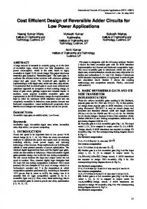
A Verification for Redundant Signed Digit Adder Circuits This is done using 3-bit inputs by generalizing the construction of all conventional adder circuits that have the 2-bit input plus 1-bit carry input (Fig. 2) [22].
x
Logic Symbol
Function
s
x
y
z
c
Type
x
y
z
z
c
s
x
y
c
s
y
z
c
s
GFA-0
GFA-1
GFA-2
GFA-3
x + y + z = 2c + s
x - y + z = 2c - s
- x + y - z = -2c + s
- x - y - z = -2c - s
Fig. 2. Four types of Generalized Full Adder Circuits. ([22])
The GFAC is a synthesis of two circuits–an adder circuit, which calculates the middle sum for 3-bit inputs, and a carry arithmetic circuit, which calculates carry output. The inputs are x, y, and z, but the input logic is different for four types of the circuit considered. The outputs s and c are also different for each of the four types. In the following, we take up Type 1 (GFA-1) as an example, define its arithmetic circuits, and derive various theorems for the circuit, and then show the stability of the circuit. For the other variant types, definitions are given and various theorems are derived in the same manner. 3.2
Definition of the GFAC Type 1 (GFA-1)
The GFAC Type 1 (GFA-1) is an arithmetic element in which the relationship between the inputs x, y, and z and the outputs s and c satisfy the equation x − y + z = 2c − s. The full adder circuit GF A1AdderStr(x, y, z) and the carry arithmetic circuit GF A1CarryStr(x, y, z) are defined as follows. By synthesizing these two circuits, we compose the generalized full adder circuit BitGF A1Str(x, y, z). Definition 6. Definition of internal adder circuit: Type 1 Let x,y,z be sets. The functor GF A1AdderStr(x, y, z) yielding an unsplit non void strict non empty many sorted signature with arity held in gates and Boolean denotation held in gates is defined as follows: (i) GF A1AdderStr(x, y, z) = 1GateCircStr(hx, yi, xor2c) + · 1GateCircStr(h[hx, yi, xor2c], zi, xor2c) where 2-input logical operator xor2c is a function from set Boolean2 to Boolean on the circuit 1GateCircStr(p, f ) and the result sorts (output) of the inputs hx1 , x2 i 219
K. Wasaki is defined by x1 ⊕ not(x2 ) [21]. The functor GF A1AdderCirc(x, y, z) yielding a strict Boolean circuit of GF A1AdderStr(x, y, z) with denotation held in gates is defined by: (ii) GF A1AdderCirc(x, y, z) = 1GateCircuit(x, y, xor2c) + · 1GateCircuit([hx, yi, xor2c], z, xor2c) . For the result sorts (adderoutput : (s)), the functor GF A1AdderOutput(x, y, z) yields an element of InnerV ertices(GF A1AdderStr(x, y, z)) and is defined as follows: (iii) GF A1AdderOutput(x, y, z) = [h[hx, yi, xor2c], zi, xor2c] . Definition 7. Definition of internal majority circuit: Type 1 Let x,y,z be sets. The functor GF A1CarryStr(x, y, z) yielding an unsplit non void strict non empty many sorted signature with arity held in gates and Boolean denotation held in gates is defined as follows: (i) GF A1CarryStr(x, y, z) = (1GateCircStr(hx, yi, and2c) + · 1GateCircStr(hy, zi, and2a) + · 1GateCircStr(hz, xi, and2)) + · 1GateCircStr(h[hx, yi, and2c], [hy, zi, and2a], [hz, xi, and2]i, or3) where 2-input logical operators and2c, and2a, and2 are a function from set Boolean2 to Boolean on the circuit 1GateCircStr(p, f ); the result sorts (output) of the inputs hx1 , x2 i is defined by x1 ∧ not(x2 ), not(x1 ) ∧ x2 , and x1 ∧ x2 , respectively [21][19]; 3-input logical operator or3 is a function from set Boolean3 to Boolean on the circuit 1GateCircStr(p, f ); and the result sorts (output) of the inputs hx1 , x2 , x3 i is defined by x1 ∨ x2 ∨ x3 [19]. The functor GF A1CarryCirc(x, y, z) yielding a strict Boolean circuit of GF A1CarryStr(x, y, z) with denotation held in gates is defined by: (ii) GF A1CarryCirc(x, y, z) = (1GateCircuit(x, y, and2c) + · 1GateCircuit(y, z, and2a) + · 1GateCircuit(z, x, and2)) + · 1GateCircuit([hx, yi, and2c], [hy, zi, and2a], [hz, xi, and2], or3). For the result sorts (carryoutput : (c)), the functor GF A1CarryOutput(x, y, z) yields an element of InnerV ertices(GF A1CarryStr(x, y, z)) and is defined as follows:
220
A Verification for Redundant Signed Digit Adder Circuits (iii) GF A1CarryOutput(x, y, z) = [h[hx, yi, and2c], [hy, zi, and2a], [hz, xi, and2]i, or3] . Definition 8. Combining of GFAC Type 1 elements Let x,y,z be sets. The functor BitGF A1Str(x, y, z) yields an unsplit non void strict non empty many sorted signature with arity held in gates and Boolean denotation held in gates and is defined as follows: (i) BitGF A1Str(x, y, z) = GF A1AdderStr(x, y, z)+· GF A1CarryStr(x, y, z). The functor BitGF A1Circ(x, y, z) yielding a strict Boolean circuit of BitGFA1Str (x, y, z) with denotation held in gates is defined by: (ii) BitGF A1Circ(x, y, z) = GF A1AdderCirc(x, y, z) + · GF A1CarryCirc(x, y, z). 3.3
Propositions for Input and Output Signal of Circuits
Propositions for carrier, InputVertices, InnerVertices as internal signal states and input and output signals can be proved based on the definitions of the calculation circuits [21]. Proposition 4. Propositions for the internal adder circuit The following propositions of the internal adder circuit are true: (i) For all sets x,y,z holds InnerV ertices(GF A1AdderStr(x, y, z)) is a binary relation, (ii) For all sets x,y,z holds the carrier of GF A1AdderStr(x, y, z) = {x, y, z} ∪ {[hx, yi, xor2c], [h[hx, yi, xor2c], zi, xor2c]}, (iii) For all sets x,y,z holds InnerV ertices(GF A1AdderStr(x, y, z)) = {[hx, yi, xor2c], [h[hx, yi, xor2c], zi, xor2c]}, and (iv) For all non pair sets x,y,z holds InputV ertices(GF A1AdderStr(x, y, z)) = {x, y, z}. Proposition 5. Propositions for the majority circuit The following propositions for the majority circuit are true: (i) For all sets x,y,z holds InnerV ertices(GF A1CarryStr(x, y, z)) is a binary relation, (ii) For all sets x,y,z holds the carrier of GF A1CarryStr(x, y, z) = {x, y, z} ∪ {[hx, yi, and2c], [hy, zi, and2a], [hz, xi, and2]} ∪ {[h[hx, yi, and2c], [hy, zi, and2a], [hz, xi, and2]i, or3]}, (iii) For all sets x,y,z holds InnerV ertices(GF A1CarryStr(x, y, z)) 221
K. Wasaki = {[hx, yi, and2c], [hy, zi, and2a], [hz, xi, and2]} ∪ {[h[hx, yi, and2c], [hy, zi, and2a], [hz, xi, and2]i, or3]},and (iv) For all non pair sets x,y,z holds InputV ertices(GF A1CarryStr(x, y, z)) = {x, y, z}. Proposition 6. Propositions for GFAC: Type 1 The following propositions are true: (i) For all sets x,y,z holds InnerV ertices(BitGF A1StrStr(x, y, z)) is a binary relation, (ii) For all sets x,y,z holds the carrier of BitGF A1StrStr(x, y, z) = (the carrier of GF A1AdderStr(x, y, z)) ∪ (the carrier of GF A1CarryStr(x, y, z)), (iii) For all sets x,y,z holds InnerV ertices(BitGF A1StrStr(x, y, z)) = (InnerV ertices(GF A1AdderStr(x, y, z))) ∪ (InnerV ertices(GF A1CarryStr(x, y, z))), and (iv) For all non pair sets x,y,z holds InputV ertices(BitGF A1StrStr(x, y, z)) = {x, y, z}. 3.4
Propositions for the Stability of GFAC
Propositions for circuit stability can be proved based on the definitions of combined circuit structures for GFAC: Type 1, BitGFA1Str(x, y, z) [21]. Proposition 7. Calculation outputs of GFAC: Type 1 The following proposition of the GFAC type-1 after two steps of computation is true: (i) Let x,y,z be sets. Let s be a state of BitGF A1Circ(x, y, z) and a1 , a2 , a3 be elements of Boolean. Suppose a1 = s(x) and a2 = s(y) and a3 = s(z). Then, (F ollowing(s, 2))(GF A1AdderOutput(x, y, z)) = not(a1 ⊕ no(a2) ⊕ a3), and (F ollowing(s, 2))(GF A1CarryOutput(x, y, z)) = (a1 ∧ not(a2 )) ∨ (not(a2 ) ∧ a3 ) ∨ (a3 ∧ a1 )). Finally, we have the main result for the stability of the combined circuit structure for GFAC: Type 1, BitGFA1Str(x, y, z), namely that it is stable after two steps of computation [21]. Proposition 8. Stability of the GFAC: Type 1 We state the following proposition of the GFAC type-1 after two steps of computation: (i) Let x,y,z be sets. Let s be a state of BitGF A1Circ(x, y, z). Then, F ollowing(s, 2) is stable.
222
A Verification for Redundant Signed Digit Adder Circuits [Proof ] As a prerequisite, we assume the internal signal points of the circuit to differ from the input signal points x, y, and z. The circuit structure S is assumed to be BitGF A1Str(x, y, z). Now, we have to show that s1 = s2 for states of the entire circuit S (BitGF A1Circ(x, y, z)), where s1 is taken as F ollowing(s, 2) (state after the operation of two steps) of given s, and s2 is F ollowing(F ollowing(s, 2)) (state after operation of three steps). First, [A]: the carrier of S equals dom(s1 ), and the carrier of S equals dom(s2 ) by [15]:Th.4. [B]: the carrier of S equals InnerVertices(GFA1AdderStr (x, y, z)) ∪ InnerVertices (GF A1CarryStr(x, y, z)) by Prop.6. Now, assume set a being an element of the carrier of S, then a ∈ {x, y, z} or a ∈ {[hx, yi, xor2c], [h[hx, yi, xor2c], zi, xor2c]} or a ∈ {[hx, yi, and2c], [hy, zi, and2a], [hz, xi, and2]} or a ∈ {[h[hx, yi, and2c], [hy, zi, and2a], [hz, xi, and2]i, or3]} by [B], [28]:Th.8. Then, [C]: a = x or a = y or a = b or a = [hx, yi, xor2c] or a = [h[hx, yi, xor2c], zi, xor2c] or a = [hx, yi, and2c] or a = [hy, zi, and2a] or a = [hz, xi, and2] or a = [h[hx, yi, and2c], [hy, zi, and2a], [hz, xi, and2]i, or3] by [29]:Th.8. Second, [D]: as the input signals x, y, z are not included in the output signals from logical gates, the following are always true s2 (x) = s1 (x) and s1 (x) = s(x) and s2 (y) = s1 (y) and s1 (y) = s(y) and s2 (c) = s1 (c) and s1 (c) = s(c). Next, [E]: s1 ([h[hx, yi, xor2c], zi, xor2c]) = s1 (GF A1AdderOutput (x, y, z)) by Def.6, then s1 ([h[hx, yi, xor2c], zi, xor2c]) = not(s1 (x) ⊕ not(s1 (y)) ⊕ s1 (c)) by logical equivalency in Prop.4. As the F ollowing computation is repeatedly applied, we have the calculation result of the adder output: s2 ([h[hx, yi, xor2], ci, xor2 ]) = not(s1 (x) ⊕ not(s1 (y)) ⊕ s1 (c)). Similarly, [F]: s1 ([h[hx, yi, and2c], [hy, zi, and2a], [hz, xi, and2]i, or3] = s1 (GF A1CarryOutput(x, y, z)) by Def.7, then s1 ([h[hx, yi, and2c], [hy, zi, and2a], [hz, xi, and2] i, or3] = (s1 (x) ∧ not(s1 (y))) ∨ (not(s1 (y)) ∧ s1 (c)) ∨ (s1 (c) ∧ s1 (x)) by logical equivalency in Prop.5. By continuing to apply the F ollowing computation, we obtain the calculation result of the majority output: s2 ([h[hx, yi, and2c], [hy, zi, and2a], [hz, xi, and2]i, or3] = (s1 (x) ∧ not(s1 (y))) ∨ (not(s1 (y)) ∧ s1 (c)) ∨ (s1 (c) ∧ s1 (x)). Finally, s2 (a) = s1 (a) by [C]∼[F], thus we prove the equation s1 = s2 by [A] and [30]:Th.9. [end]
4
Redundant Signed Digit Adder Circuit
In this section, we introduce the carry-saved adder arithmetic circuit [22] using redundant signed digit (RSD) representation [23][24] employed in the interior operation of the Montgomery multiplier as an actual example of arithmetic circuits. We present the circuit definition, various propositions of it, and verify its operation. Furthermore, we employ the Mizar proof checker to testify the correctness of the proofs. 223
K. Wasaki 4.1
Structure of RSD Adder Circuits
The redundant signed digit adder (RSDA) is a proposal for an arithmetic circuit with the function of preventing speed degradation that accompanies carry propagation [22]. The design postpones carry-related calculations up to a certain layer at which point a final adding output is done by extending bit-expressions to carry out input and output activities for the adder. The circuit composition is improved– from a single Boolean, such as {0, 1}, to two combined pairs of Boolean elements, such as {h0, 0i, h1, 0i, h0, 1i} – to minimize carries that take place at the time of adding as much as possible (Fig. 3).
-
x n-1
x
+
-
x n-2
n-1
x
-
+
-
x n-3
n-2
-
y n-1
x
+
-
x0
n-3
x
-
y n-2
+ 0
-
y n-3
0
y0
Layer I
0
y
0
-
+
t n-1
t
+
-
+
t n-1
n-1
y
n-1
t
+
-
+
t n-2
n-1
y
n-2
t
+
y
n-3
-
0
0
-
t n-3
n-2
+
+
t0
t
0
Layer II 0
-
z n+1
z
-
+ n+1
zn
z
-
+ n
z n-1
z
+
-
n-1
z n-2
z
-
+ n-2
z n-3
z
+
-
1
z0
z
+ 0
Fig. 3. Circuit configuration of redundant signed digit adder. ([22])
The arithmetic circuit which calculates an intermediate sum using RSD expressions connects by a two-step pipeline at Layer I using the GFAC generalized by 3-inputs/2-outputs [22]. We have shown in Section 3 that the whole GFAC operation stabilizes in two steps. Since the RSD adder has a two-stage pipeline construction after synthesis, the calculation result stabilizes through four steps in total. The pipeline terminal part (Layer II) is constructed with a simple AND circuit (which stabilizes in a single step) to add up carries that have been postponed for succession in the next step with RSD expressions to attain the final result of adding. Therewith, the whole operation stabilizes in five steps total. 4.2
Definition of RSDA Layer I (the intermediate sum)
Layer I (the intermediate sum) of the RSDA carries out RSD adding between cin , the input from the intermediate carry-save from the k − 1 bit digit and the k − 1 224
A Verification for Redundant Signed Digit Adder Circuits − + − bit digit inputs {x+ k , xk } and {yk , yk } to attain the intermediate sum output as + − well as the carry pair saved, {tk , tk+1 }. The Layer I adder BitRSD1Str(x− , x+ , y − , y + , cin ), which is a serial composition of GFAC Type 2 (BitGF A2Str) and GFAC Type 1 (BitGF A1Str) on the sum output line is defined as follows.
Definition 9. Combining of RSDA Layer I Let x− , x+ , y − , y + , cin be sets. The functor BitRSD1Str(x− , x+ , y − , y + , cin ) yields an unsplit non void strict non empty many sorted signature with arity held in gates and Boolean denotation held in gates and is defined as follows: (i) BitRSD1Str(x− , x+ , y − , y + , cin ) = BitGF A2Str(x− , x+ , y − ) + · BitGF A1Str(GF A2AdderOutput(x− , x+ , y − ), cin , y + ) . The functor BitRSD1Circ(x− , x+ , y − , y + , cin ) yielding a strict Boolean circuit of BitRSD1Str with denotation held in gates is defined by: (ii) BitRSD1Circ(x− , x+ , y − , y + , cin ) = BitGF A2Circ(x− , x+ , y − ) + · BitGF A1Circ(GF A2AdderOutput(x− , x+ , y − ), cin , y + ) . 4.3
Propositions for Input and Output Signals of RSDA Layer I
Propositions for carrier, InputVertices, InnerVertices as internal signal states and input and output signals can be proved based on the definitions of calculation circuits by Def.9. Proposition 9. Propositions for the RSDA Layer I circuit The following propositions are true: (i) For all sets x− , x+ , y − , y + , cin holds InnerV ertices(BitRSD1Str(x− , x+ , y − , y + , cin )) is a binary relation, (ii) For all sets x− , x+ , y − , y + , cin holds the carrier of BitRSD1Str(x− , x+ , y − , y + , cin ) = {x− , x+ , y − , y + , cin } ∪ {[hx− , x+ i, xor2c], GF A2AdderOutput(x− , x+ , y − )} ∪ {[hx− , x+ i, and2c], [hx+ , y − i, and2a], [hy − , x− i, and2], GF A2CarryOutput(x− , x+ , y − )} ∪ {[hGF A2AdderOutput(x− , x+ , y − ), cin i, xor2c], GF A1AdderOutput(GF A2AdderOutput(x− , x+ , y − ), cin , y + )} ∪ {[hGF A2AdderOutput(x− , x+ , y − ), cin i, and2c], [hcin , y + i, and2a], [hy + , GF A2AdderOutput(x− , x+ , y − )i, and2], GF A1CarryOutput(GF A2AdderOutput(x− , x+ , y − ), cin , y + )}, and 225
K. Wasaki (iii) For all non pair sets x− , x+ , y − , y + ,set cin holds InputV ertices(BitRSD1Str(x− , x+ , y − , y + , cin )) = {x− , x+ , y − , y + , cin }. 4.4
Propositions for the Stability of RSDA Layer I
Propositions for circuit stability can be proved based on the definitions of combined circuit structures using RSDA Layer I, BitRSD1Str. Proposition 10. Calculation outputs of RSDA Layer I The following proposition of the RSDA Layer I after four steps of computation is true: (i) Let x− , x+ , y − , y + , cin be sets. Let s be a state of BitRSD1Circ(x− , x+ , y − , y , cin ) and a1 ,a2 ,a3 ,a4 ,a5 be elements of Boolean. Suppose a1 = s(x− ), a2 = s(x+ ), a3 = s(y − ), a4 = s(y + ) and a5 = s(cin ). Then, for an output signal t− , we have F ollowing(s, 4)(BitRSD1Output−(x− , x+ , y − , y + , cin )) = not(not(a1 ) ⊕ a2 ⊕ not(a3 ) ⊕ a4 ⊕ not(a5 )). +
We have a similar proposition for output signal t+ as BitRSD1Output+(x− , x+ , y − , y + , cin ). Now, we have a result for the stability of the combined circuit structure, as RSDA Layer I, BitRSD1Circ is stable after four (2 + 2) steps of computation. Proposition 11. Stability of RSDA Layer I We state the following proposition of RSDA Layer I after four steps of computation: (i) Let x− , x+ , y − , y + , cin be sets. Let s be a state of BitRSD1Circ(x− , x+ , y − , y , cin ). Then, F ollowing(s, 4) is stable by using Prop.8 for GFAC as Type 1,2 and [20]:Th.20 (after 2 + 2 steps of computation). +
4.5
Definition of RSDA Layer I+II
For the circuit construction of RSDA/Layer I+II (the final sum), we merge the intermediate sum from the k bit digit and the intermediate carry saved from the − k−2 and k−1 bit digit inputs and then output the final result (sum) pair {zk+, zk+1 }. − + − + + We define the Layer I+II adder BitRSDStr(x , x , y , y , cin , t ), which is a serial composition between RSDA Layer I(BitRSD1Str) and a combined logical AND gates circuit (1GateCircStr(p, and2c) + ·1GateCircStr(p, and2a)) with the carry and sum signals as follows.
226
A Verification for Redundant Signed Digit Adder Circuits Definition 10. Combining of RSDA Layer I+II Let x− , x+ , y − , y + , cin , t+ be sets. The functor BitRSDStr(x− , x+ , y − , y + , cin , t+ ) yields an unsplit non void strict non empty many sorted signature with arity held in gates and Boolean denotation held in gates and is defined as follows: (i) BitRSDStr(x− , x+ , y − , y + , cin , t+ ) = BitRSD1Str(x− , x+ , y − , y + , cin ) + · 1GateCircStr(ht+ , BitRSD1Output−(x− , x+ , y − , y + , cin )i, and2c) + · 1GateCircStr(ht+ , BitRSD1Output−(x− , x+ , y − , y + , cin )i, and2a) . The functor BitRSDCirc(x− , x+ , y − , y + , cin , t+ ) yielding a strict Boolean circuit of BitRSDStr with denotation held in gates is defined by: (ii) BitRSDCirc(x− , x+ , y − , y + , cin , t+ ) = BitRSD1Circ(x− , x+ , y − , y + , cin ) + · 1GateCircuit(t+ , BitRSD1Output−(x− , x+ , y − , y + , cin ), and2c) + · 1GateCircuit(t+ , BitRSD1Output−(x− , x+ , y − , y + , cin ), and2a) . 4.6
Propositions for Input and Output Signals of RSDA Layer I+II
Propositions for carrier, InputVertices, InnerVertices as internal signal states and input and output signals can be proved based on the definitions of the calculation circuits by Def.10. Proposition 12. Propositions for the RSDA Layer I+II circuit The following propositions are true: (i) For all sets x− , x+ , y − , y + , cin , t+ holds InnerV ertices(BitRSDStr(x− , x+ , y − , y + , cin , t+ )) is a binary relation, (ii) For all sets x− , x+ , y − , y + , cin , t+ holds the carrier of BitRSDStr(x− , x+ , y − , y + , cin , t+ ) = {x− , x+ , y − , y + , cin , t+ } ∪ {[hx− , x+ i, xor2c], GF A2AdderOutput(x− , x+ , y − )} ∪ {[hx− , x+ i, and2c], [hx+ , y − i, and2a], [hy − , x− i, and2], GF A2CarryOutput(x− , x+ , y − )} ∪ {[hGF A2AdderOutput(x− , x+ , y − ), cin i, xor2c], GF A1AdderOutput(GF A2AdderOutput(x− , x+ , y − ), cin , y + )} ∪ {[hGF A2AdderOutput(x− , x+ , y − ), cin i, and2c], [hcin , y + i, and2a], [hy + , GF A2AdderOutput(x− , x+ , y − )i, and2], GF A1CarryOutput(GF A2AdderOutput(x− , x+ , y − ), cin , y + )} ∪ + {[ht , BitRSD1Output−(x− , x+ , y − , y + , cin )i, and2c], [ht+ , BitRSD1Output−(x− , x+ , y − , y + , cin )i, and2a]} , and 227
K. Wasaki (iii) For all non pair sets x− , x+ , y − , y + ,set cin , t+ holds InputV ertices(BitRSDStr(x− , x+ , y − , y + , cin , t+ )) = {x− , x+ , y − , y + , cin , t+ }. 4.7
Propositions for Stability of RSDA Layer I+II
Propositions for circuit stability can be proved based on definitions of the combined circuit structure for RSDA Layer I+II, BitRSDStr. Proposition 13. Calculation outputs of RSDA Layer I+II The following proposition of the RSDA Layer I+II after five steps (4 + 1 steps) of computation is true: (i) Let x− , x+ , y − , y + , cin , t+ be sets. Let s be a state of BitRSDCirc(x− , x+ , y , y + , cin , t+ ) and a1 ,a2 ,a3 ,a4 ,a5 ,a6 be elements of Boolean. Suppose a1 = s(x− ), a2 = s(x+ ), a3 = s(y − ), a4 = s(y + ), a5 = s(cin ) and a6 = s(t+ ). Then, with respect to output signal z + , we have F ollowing(s, 5)(BitRSDOutput+(x− , x+ , y − , y + , cin , t+ )) = a6 ∧ (not(a1 ) ⊕ a2 ⊕ not(a3 ) ⊕ a4 ⊕ not(a5 ). −
We have a similar proposition for output signal z − as BitRSDOutput− (x− , x+ , y − , y + , cin , t+ ). Finally, as RSDA Layer I+II, BitRSDCirc is stable after five (4 + 1) steps of computation, we have the main result of stability for the combined circuit structure. Proposition 14. Stability of RSDA Layer I+II We state the following proposition of the RSDA Layer I+II after five steps (4 + 1 steps) of computation: (i) Let x− , x+ , y − , y + , cin , t+ be sets. Let s be a state of BitRSDCirc(x− , x+ , y , y + , cin , t+ ). Then, F ollowing(s, 5) is stable by using Prop.11 for RSDA Layer I, Prop.3 and [20]:Th.20 (after 4 + 1 steps of computation). −
5
Conclusion
By using mathematical models of an arithmetic logic unit based on many sorted algebraic structures, we successfully proved the important properties of an example of a calculation circuit, the RSD adder. The stability of the RSD adder circuit example is proved based on definitions and theorems about logic operators, hardware gates, and signal line connections using the Mizar proof checking system as a formal verification tool. In future research on circuit verification by proof checking, we plan to do design verifications of such circuits as Wallace-Tree type multipliers, Montgomery high-speed multipliers, RSA encryption processing units, and various high speed operational circuits necessary for arithmetic logic units. 228
A Verification for Redundant Signed Digit Adder Circuits
Acknowledgement This research was strongly inspired by Professor A. Trybulec, Y. Nakamura, P. Rudnicki and G. Bancerek [11][12][13][14][15][16][17][18][20]. I would like to express my deep thanks to Professor Andrzej Trybulec and the Mizar project teams around the world.
References 1. Ichikawa, S., et al.: A Connection Sleeves Line Architecture (Pipelined MIMD). The 37th Annual Conference of Information Processing Society of Japan, 4, N-4 (1988). 2. Kleeman, L., Cantoni, A.: Can Redundancy and Masking Improve the Performance of Synchronizers? IEEE Trans. Computers, C-35(7) (1986) 643–646. 3. Stoffers, K. E.: Test Sets for Combinational logic – The Edge – Tracing Approach. IEEE Trans. Computers, C-29(8) (1980) 741–746. 4. Strangio, C. E.: DIGITAL ELECTRONICS: Fundamental Concepts and Applications. Prentice-Hall Inc. (1980) 355–385. 5. Unger, S. H., Tan, C. J.: Clocking Schemes for High-Speed Digital Systems. IEEE Trans. Computers, C-35(10) (1986) 880–895. 6. Ishiura, N., Takahashi, M., Yajima, S.: Time-Symbolic Simulation for Accurate Timing Verification of Logic Circuits. Trans. of Information Processing Society of Japan, 31(12) (1990) 1832–1839. 7. Ogura, S.: The Development Methods in CPLD/FPGA. Technical Paper of the 1st Japanese FPGA/PLD Design Conference, 4 (1993) 46–62. 8. Nakamura, Y., Nishiyama, T., Fuwa, Y.: Signal Propagation Timing Check System in Multi-Level Sequential Circuits. Trans. of the Institute of Electronics, Information and Communication Engineers, 75(12) (1992) 1826–1836. 9. Nishiyama, T., Fuwa, Y., Eguchi, M., Nakamura, Y.: A Digital Circuits Timing Verification Scheme based on a Clock Model. Trans. of the Institute of Electronics, Information and Communication Engineers, 77(6) (1994) 860–870. 10. Nishiyama, T., Mizuhara, Y.: Binary Arithmetics. Formalized Mathematics, 4(1) (1993) 83–86. 11. Trybulec, A.: Many-sorted Sets. Formalized Mathematics, 4(1) (1993) 15–22. 12. Trybulec, A.: Many Sorted Algebras. Formalized Mathematics, 5(1) (1996) 37–42. 13. Nakamura, Y., Rudnicki, P., Trybulec, A., Kawamoto, P. N.: Preliminaries to Circuits, I. Formalized Mathematics, 5(2) (1996) 167–172. 14. Nakamura, Y., Rudnicki, P., Trybulec, A., Kawamoto, P. N.: Preliminaries to Circuits, II. Formalized Mathematics, 5(2) (1996) 215–220. 15. Nakamura, Y., Rudnicki, P., Trybulec, A., Kawamoto, P. N.: Introduction to Circuits, I. Formalized Mathematics, 5(2) (1996) 227–232. 16. Nakamura, Y., Rudnicki, P., Trybulec, A., Kawamoto, P. N.: Introduction to Circuits, II. Formalized Mathematics, 5(2) (1996) 273–278. 17. Nakamura, Y., Bancerek, G.: Combining of Circuits. Formalized Mathematics, 5(2) (1996) 283–295. 18. Bancerek, G., Nakamura, Y.: Full Adder Circuit, Part I. Formalized Mathematics, 5(3) (1996) 367–380. 19. Wasaki, K., Kawamoto, P. N.: 2’s Complement Circuits, Part I. Formalized Mathematics, 6(2) (1996) 189–197. 20. Bancerek, G., Yamaguchi, S., Shidama, Y.: Combining of Multi Cell Circuits. Formalized Mathematics, 10(1) (2002) 47–64.
229
K. Wasaki 21. Yamaguchi, S., Wasaki, K., Shimoi, N.: Generalized Full Adder Circuits (GFAs), Part I. Formalized Mathematics, 13(4) (2005) 549–571. 22. Savas, E: A Carry-Free Architecture for Montgomery Inversion. IEEE Trans. Computers, 54(12) (2005) 1508–1519. 23. Avizienis, A.: Signed-Digit Number Representation for Fast Parallel Arithmetic. IRE Trans. Electronic Computers, 10 (1961) 389–400. 24. Vandemeulebroecke, A., Vanzieleghem, E., Denayer, T., Jespers, P. G. A.: A New Carry-Free Division Algorithm and its Application to a Single-Chip 1024-b RSA Processor. IEEE J. Solid-State Circuits, 25(3) (1990) 748–755. 25. Bonarska, E.: An Introduction to PC Mizar. In Roman Matuszewski, editor, Series of Fondation Philippe le Hodey, Brussels (1990). 26. Trybulec, A., Rudnicki, P.: A Collection of TEXed Mizar Abstracts. University of Alberta, Canada (1989). 27. Mizar Proof Checker: http://mizar.org/ ´ 28. Trybulec, Z., Swieczkowska, H.: Boolean Properties of Sets. Formalized Mathematics, 1(1) (1990) 17–23. 29. Trybulec, A.: Enumerated Sets. Formalized Mathematics, 1(1) (1990) 25–34. 30. Byli´ nski, C.: Functions and Their Basic Properties. Formalized Mathematics, 1(1) (1990) 55–65.
230