A. Aljaafreh a, A. Al Assaf b. aTafila Technical University , Tafila, Jordan ; b King Abdullah II Design and Development Bureau, .... energy of seismic waves that could be generated from a military vehicle and measured in the area that ..... ZB is a wireless network protocol specifically designed for low data rate and low-power ...
A Wireless Sensor Network Design and Implementation for Vehicle Detection, Classification, and Tracking A. Aljaafreh a, A. Al Assaf b Tafila Technical University , Tafila, Jordan ; b King Abdullah II Design and Development Bureau, Head of applied research , Amman , Jordan
a
ABSTRACT Vehicle intrusion is considered a significant threat for critical zones specially the militarized zones and therefore vehicles monitoring has a great importance. In this paper a small wireless sensor network for vehicle intrusion monitoring consists of a five inexpensive sensor nodes distributed over a small area and connected with a gateway using star topology has been designed and implemented. The system is able to detect a passage of an intrusive vehicle, classify it either wheeled or tracked, and track the direction of its movement. The approach is based on Vehicle’s ground vibrations for detection, vehicle’s acoustic signature for classification and the Energy- based target localization for tracking. Detection and classification are implemented by using different algorithms and techniques including Analog to Digital Conversion, Fast Fourier Transformation (FFT) and Neural Network .All of these algorithms and techniques are implemented locally in the sensor node using Microchip dsPIC digital signal controller. Results are sent from the sensor node to the gateway using ZigBee technology and then from the gateway to a web server using GPRS technology. Keywords: vehicle tracking, Fast Fourier Transformation, Neural Networks, vehicle intrusion, dsPIC, Neural Network
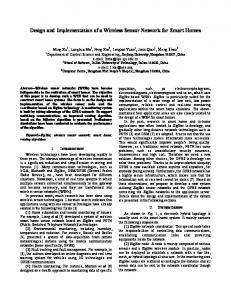
1. INTRODUCTION Landmines were used in the past and still being used as a defensive method to protect countries border against intruding of enemy vehicles. What makes landmines so abhorrent is the indiscriminate destruction they cause. Landmines kill about 15,000 to 20,000 people every year. Sadly, an estimated 80 percent of landmine victims are civilians; one-third of these are children [1]. For these reasons, the military governments are working to find a defensive system where the safety and security are present. Intrusion monitoring system is considered a secure and safe. In contrast of landmines, it can alert the military command and control units of the passage of an intrusive vehicle, and then leaves to the responsible person the decision of making the best reaction to repel the intrusion. Although the intrusion monitoring has a great importance for many places such as borders, airports, governmental properties, and companies. It is hard to design a universal security system to be used for all these places; this is because of the difference in the nature of threat and environment. 1.1 Overview An intrusion monitoring system was designed and implemented to monitor a small militarized zone against intruding the enemy’s vehicles. As shown in figure 1, the system is designed based on the Wireless Sensor Network (WSN), it consists of a four sensor nodes and one gateway. The key elements of the system are detection, classification, and tracking. This requires that the system is able to detect the passage of armed vehicle, classify it into several classes, and track the direction of its movement. The system was designed to classify the intrusive vehicle into two classes; either wheeled or tracked. Our approach is based on the ground vibrations that are generated by the vehicle for detection, the acoustic signature of the vehicle for classification, and the energy of acoustic signals localization and tracking. Signal processing and communication tasks for detection and classification are implemented locally in the sensor node using Microchip Digital Signal Peripheral Interface Controller (dsPIC). The results are sent initially from the sensor node to the gateway using ZigBee (ZB) technology and then to a web server using General Packet Radio Service (GPRS) technology.
Airborne Intelligence, Surveillance, Reconnaissance (ISR) Systems and Applications X, edited by Daniel J. Henry, Proc. of SPIE Vol. 8713, 871305 · © 2013 SPIE · CCC code: 0277-786X/13/$18 · doi: 10.1117/12.2029835
Proc. of SPIE Vol. 8713 871305-1 Downloaded From: http://spiedigitallibrary.org/ on 11/04/2015 Terms of Use: http://spiedigitallibrary.org/ss/TermsOfUse.aspx
T77T Sensor node
Tracked T vehicle
4
Web server
Gateway
Monitor
Figure 1. O Overview of the monitoring sysstem
2.2 Related w work Many of exciiting researchees and projectts ongoing aree related with h military appllications use th the WSN to detect, classifyy, and determinne the directiion of travell of intrudingg vehicles. The T Remotely y Monitored Battlefield Sensor System m (REMBASS)) which is the U.S. Army’s type standardd Unattended Ground G Senso or (UGS) systeem exemplifiees an intrusionn monitoring ssystem that in i use today [2]. Relativee projects usse different algorithms a annd techniquess for sensingg, processing, aand communnication. Thesse algorithmss and techniq ques vary in n their compplexity, reliab bility, fidelityy, efficiency, coost, and powerr consumption n.
3. ME ETHODOL LOGY dels that are reelated to the system s were established. e D Designing and implementingg Before designning the systeem, some mod the system w were based on these models;; those modells are threat model, m environ nmental modeel, and system m model. In thee threat model,, the threatenning object is an intrusive armed vehiclle; this intrussive vehicle iss being classified into twoo classes; eitheer wheeled or tracked. Thee semi trackedd vehicles weere considered d as tracked vvehicles, also only a singlee vehicle is preesent in the seensor network k at a specifieed space and time. The env vironmental pparameters succh as weatherr, geographical variations annd noise havee a great effecct on the systtem efficiency y. To increasee the system efficiency thee mperature rangee spanning beetween -25 C0 to +70 C0 .wee following asssumptions werre considered:: firstly the opperational tem allow for thee possibility of o rain but wee rule out thee possibility of o snow. Seco ondly, harsh tterrain and th he presence of obstacles are allowed withh assumption that they donn’t affect in co onnection betw ween node annd the gateway y. And finallyy the noise is aallowed but with w the assum mption that thee noise powerr is upper bounded. In the ssystem modell to practicallyy implement thhe monitoringg system we may m need thoousands of no odes dependin ng on the sizze of the areaa that is to bee monitored. Inn this study a small numberr of nodes weere used to bu uild a small prrototype. So, iimplementing g the system iss limited to a sm mall area.
Proc. of SPIE Vol. 8713 871305-2 Downloaded From: http://spiedigitallibrary.org/ on 11/04/2015 Terms of Use: http://spiedigitallibrary.org/ss/TermsOfUse.aspx
3.1 Design Methodology The intrusion monitoring system was designed to be able to detect the passage of an armed vehicle, classify it either as a wheeled or a tracked, and track the direction of its movement. Each of these system elements has its own techniques to implement it. 3.2 Detection Detection requires that the system discriminates between the passage of a vehicle and whether not. Many of sensing modes could be used for vehicle detection. A one that is so appropriate for our application is seismic (ground vibrations) mode. Detection the passage of a vehicle based on its ground vibrations has many advantages such as long sensing range, no line-of-sight requirement, low power, and passive nature [2]. The contact between the moving abject and the ground surface causes a vibration which generates seismic waves that travel through the ground surface. The energy of these waves depends on the nature of both the moving abject and the ground surface. Most of military vehicles generate ground vibrations that have high energy which is increased on rough terrains. A threshold value is assigned to the less energy of seismic waves that could be generated from a military vehicle and measured in the area that is to be monitored. The sensor node continuously measures the ground vibrations energy; if it is equal or greater than the threshold value then a vehicle is detected. Figure 2 clarifies the principle of detection process. The energy of ground vibrations is measured repeatedly each 0.01s using a small vibration sensor connected to the microcontroller. Detection a vehicle will trigger the classification process, i.e. the classification process is not implemented unless a vehicle was detected. Therefore, detection process plays a major role in reducing the node energy that is could be consumed by classification process. START
Measure the energy of ground vibration
Is the measured value equal or greater than the th h ld l ?
No
Yes A vehicle was detected, start classification
End
Figure 2. Vehicle detection process
3.3 Classification Classification requires that the system labels the detected vehicle as belonging to either wheel-type or track-type vehicle. Moving ground vehicles affect the environment in different ways by emitting heats, sounds, magnetic field, etc. There are many approaches that investigated vehicle classification based on different kinds of signals. The most promising approach for vehicle identification is the one that is based on acoustic signals [3]. In addition to its high fidelity,
Proc. of SPIE Vol. 8713 871305-3 Downloaded From: http://spiedigitallibrary.org/ on 11/04/2015 Terms of Use: http://spiedigitallibrary.org/ss/TermsOfUse.aspx
classification the vehicle based b on its accoustic signalls has many ad-vantages sim milar to that tthe seismic seensing has [2], ght requiremennt, sensing raange, and pow wer consumpttion. Almost every movingg i.e. it meets challenges off a line-of-sig vehicle makees some kinds of noise whicch is considerred as an acou ustic signaturee. As shown iin figure 3.2 that noise cann come from thhe vibrations of the running g engine, bum mping and fricction of the vehicle tires/traacks with the ground, windd effects, etc. [44]. Vehicles of o the same kiind and workiing in similar conditions will w generate siimilar noises, or have somee kind of noisee signature thhat can be useed to classifyy vehicles [3, 4]. Thereforee, each of whheeled and traacked militaryy vehicles has ddistinctive acooustic signaturre.
Figure 3. Noise sources off a moving vehiccle
The problem now is how to t extract and d represent thee distinctive acoustic featurres that characcterize each vehicle v type. A t featuress is using the frequency sp pectrum distrib bution. If wee study the so ound spectrum m suitable way to represent these distribution, we can easily find that the sound sppectra are geenerally not evenly distribbuted; insteaad, their largee d of the frequuency band [4]]. To prove th his approach, the MATLAB B was used too components hheavily residee at lower end plot frequenccy spectra of different soun nds from diffe ferent vehicless. Figure 3.3 shows s frequenncy spectra of o six differennt vehicles sounnd; vehicles 1, 2, and 3 represent r tracck-type vehicles while veh hicles 4, 5, aand 6 represent wheel-typee vehicles. V:
ro
15
r8
x l0
4
g 2
z 3020 I
(Haj
DOD
(HZ]
Figure 4. Frrequency spectrra of six different vehicles
Figure 4 show ws that higherr energy comp ponents are geenerally distriibuted at frequ uencies less thhan 1 KHz. So, S the band of frequencies sttarting at 0 Hzz and ending at 1 KHz wass assumed to be b the band off interest. Impplementing thee classificationn process needds complex siggnal processin ng tasks in orrder to extracct and use acoustic featurees. Figure 5 shows s that thee mplemented by y applying thrree different siignal processiing algorithmss and techniqu ues; Analog too classification process is im nd Neural Nettwork (NN). A All of these algorithms a andd Digital Conversion (ADC)), Fast Fourierr Transformattion (FFT), an he sensor nodee. techniques arre implementeed locally in th AD DC
Acoustic A signaal
FFL
NN
Figure 5. Classification process algorrithm sequencce
Proc. of SPIE Vol. 8713 871305-4 Downloaded From: http://spiedigitallibrary.org/ on 11/04/2015 Terms of Use: http://spiedigitallibrary.org/ss/TermsOfUse.aspx
The acoustic signals are annalog in naturre. In order too enable the microcontrolle m er to process tthese signals, the Analog too orm. Accordinng to the Nyq quist Theorem m, Digital Conveersion (ADC)) is implementted to represennt these signaals in digital fo the sample frrequency shouuld be at leasst twice the hhighest frequeency that is to o be measuredd [5]. While describing d thee acoustic signaals previouslyy, the band off interest was aassumed to bee a lower-band signal, startting at 0 Hz an nd ending at 1 KHz. To ensuure that the siignals are adeequately samppled so that th he aliasing is avoided, a in-steead of sampliing at twice of frequency, the signals are sampled s at fiv ve times the hiighest frequen ncy, i.e. the sig gnals are samppled at a frequ uency equals 5 c a sm mall number of samples iss kHz. Acoustiic signals of vehicle havee a periodic ccharacteristic. Therefore, capturing adequate to bbe used for annalyzing the signals. s In thiss project, a window w of 512 2 samples is uused to analyzze the signalss. Figure 4.6 shhows the timee spectrum fo or a window oof acoustic sig gnals that werre generated ffrom a tracked d vehicle. Thee output of the ADC is a vecctor of 512 eleements which represents thee acoustic sign nals in time doomain. ;» pis cio 5000
05 04
03
i
PI
_
-0.3
-0.40
Figure 6. The sspectrum of 5122 samples of acoustic signals aat 5 KHZ
3.4 Fast Fou urier Transfoormation The Fast Fouurier Transform m (FFT) is a fast fa algorithm to implement the Discrete Fourier F Transsform (DFT). It I is used to me domain to its counterparrt in the frequ uency domain. Generally, thhe transform iss convert the siignal in the tim mathematicallly formulatedd by equation ( 1 ).
X k = ∑ n = 0 xnWNn N −1
(1)
Where: k = 0, 1 ,2,… …, N− 1
xn
:
The sett of N input saamples; which h are complexx numbers hav ve zeroed imag ginary parts.
X k : The set of K outputs, represent magnitudes ccorrespondingg to frequency bins. n WN n − iπ n / N : Coefficcients, which are a constants twiddle t factorr; W = e N
) The output oof ADC is thee input of FFT T, Implementingg FFT algorithhm speeds up the calculatioon required in equation ( 1 ). the 512 sam mples of acouustic signals in i time domaain generates 512 points in frequencyy domain corresponding too frequency binns that have a resolution of 9.766 Hz. Sinnce the band of o interest is th he frequenciess less than 1 KHz, K we focuss only on firstt 100 points of 512 FFT outputs and ignore the other. o Similar to [6], to siimplify the next n works inn
Proc. of SPIE Vol. 8713 871305-5 Downloaded From: http://spiedigitallibrary.org/ on 11/04/2015 Terms of Use: http://spiedigitallibrary.org/ss/TermsOfUse.aspx
classification process, the first 100 elem ments are aveeraged by pairrs. The result is a 50- dimeensional FFT-based featuree n of 19.531 H Hz and inform mation for freq quencies up too 976.563 Hzz. This can bee vector a featuure vector has a resolution modeled mathhematically byy equation ( 2 ).
XM =
X k + X k +1 2
(2))
Where: k
M
=0, 1, 2, … …, 49 =2
k
=0, 22, 4, ..., 98
Figure 3.6 sho ows the plot of o features vector of two diifferent vehicles
- vi
Normalized Magnitude
4it\ it
I1
i\ ,Y 15
:a
'-'1 m FFI' bin.
30
40
33
_
ö
50
Figure 7. 50 points feattures vector off two differennt vehicles 3.5 Neural networks Neural netwoorks consist of o a number of o processing elements callled neurons. It I is a compliicated, non-lin near, dynamicc system that tthe neurons connect c each other in somee topological structure. It is drawn from m research on n organizationn structure and behavior feattures of the human brain an and mimicking g the simplifieed informationn processing capabilities of biological neeural systems. Depending on their struucture, neurall networks caan be categorrized into mu ulti-layer feedd forward (ML LF) networks,, self-organizaation feature map (SOFM M), and adaptiive resonancee theory (ART). The MLF F network is thhe most comm monly used neetwork. In thiis project, a three t layer MLF M with sigm moid transfer functions wass used. t is used fo or classificatioon consists on ne hidden layeer. There are 550, 25, and 2 neurons n in thee The MLF nettwork model that input, hiddenn, and output layer l respectively, this is sshown in figu ure 8. The num mber of proceessing elements in the inpuut layer corresponds to the number n of feattures vector eelement obtain ned in each caaptured windoow of acoustiic signals. Thee c g to a wheel-ty ype and trackoutput nodes represent thee vehicle typess or categoriees to recognizee, which are corresponding c arcchitecture is used. u The biass type. To takee into accountt interrelations among the pprocessing eleements, full connection unit is includeed in each layyer in the netw work. The trannsfer function for all elemen nts was the siggmoid function n.
4
Input
Hidden layer
put layer
(50 new
(25 neurons)
ieurons)
Figure 8. The MLF Nettwork that is used in classifi fication
Proc. of SPIE Vol. 8713 871305-6 Downloaded From: http://spiedigitallibrary.org/ on 11/04/2015 Terms of Use: http://spiedigitallibrary.org/ss/TermsOfUse.aspx
, /
N
r
I 50
2x1
o = f2 (W2h + b2)
W1a + b1)
) o = fz(W fiiWia + b1,
+b2)
Figure 9. C Calculations inn Neural Netw works To train the neural netwoork, 300 samp ples of differeent vehicles sounds s (150 wheeled, w 1500 tracked) waas used. Thesee k were trainedd, the values of o weights andd samples weree divided into three sets as shown in tabble 1 and Once the network biases were oobtained were placed as con nstant vectors in memory off the microcon ntroller (dsPIC C® microconttroller). Table 1. Sam mples set
Training
70%
210 saamples
Validation
15%
45 sam mples
Testing
15%
45 sam mples
3.6 Trackingg Determinationn of target loocations at successive timee instants is in ntegral to traccking. Variouus algorithms,, with varyingg levels of com mplexity, have been develop ped for this pur urpose. In this project energy y-based targett localization algorithm willl be used. Eneergy-based souurce localization is motivaated by a simp ple observatio on that the soound energy level increasess when the disttance betweenn the source an nd the node beecomes smaller. By modeliing the relatioon between energy level andd distance from m the sound soource, one maay estimate thee source locattion using mu ultiple energy reading at diffferent, knownn sensor locatioons. The energgy of acousticc signals is com mputed locallly in the senso or node using the relationsh hip formulatedd by equation (3).
1 E= N
N −1
∑ x [ n⎤⎦ n=0
2
i
(3)
Where:
E : is the eneergy reading at a the sensor. xi [ n⎤⎦ : Acouustic time seriies signal in thhe sensor At a certain ttime, all sensoor nodes that detected d a vehhicle send thee value of the measured eneergy to the weeb server. Thee location of thhe vehicle caan be estimateed by implem menting the trrilateration calculation in thhe web serveer.Trilaterationn estimation is used to find an unknown location l from several reference locationss. Trilaterationn uses the disstances amongg ween referencee the locationss to estimate the coordinaate of the unkknown location. In trilateration, the diistances betw locations andd the unknow wn location caan be consideered as the raadii of many circles with centers at ev very referencee location . Thhus, the unknoown location is i the intersecttion of all the spheres.
Proc. of SPIE Vol. 8713 871305-7 Downloaded From: http://spiedigitallibrary.org/ on 11/04/2015 Terms of Use: http://spiedigitallibrary.org/ss/TermsOfUse.aspx
4. COMMUNICATION Wireless data transfer capability is the key feature of WSNs. It provides both flexibility and cost savings in deployment and maintenance compared to wire line deployments. Selecting the most appropriate wireless technology for an application is very important. Two types of wireless communication technology are used in vehicle intrusion system. As shown in figure, the ZigBee (ZB) technology is used to send the data from the sensor node to the gateway, while the GPRS technology is used to send the received data from the gateway to the web server. 4.1 ZigBee Technology ZB is a wireless network protocol specifically designed for low data rate and low-power consumption sensors networks. It provides network, security, and application support services operating on top of the IEEE 802.15.4 Medium Access Control (MAC) and Physical Layer (PHY) wireless standard [7]. Figure 4.2 shows the ZB Standard Model. ZB is expected to provide low cost and low power. The low cost allows the technology to be widely deployed in wireless control and monitoring applications, the low power usage allows longer life with smaller batteries. ZB-compliant products operate in the industrial, scientific and medical (ISM) radio bands, including 2.4GHz (global), 902 to 928MHz (Americas), and 868MHz (Europe). ZB addressing space of up to 65,535 devices, each device has a unique identification [7]. The ZB protocol wireless network may assume many types of configurations. Nodes could be connected using star, cluster tree, mesh, or hybrid network. The simplest one is the star topology was used in designing and implementing this project. In the star topology, the communication is established between end devices (sensor nodes) and a single central controller, called the PAN coordinator (gateway). Each start network chooses a PAN identifier, which is not currently used by any other network within the radio sphere of influence. This allows the star network to operate independently [8]. Using the star topology in not practical for our application. Addition of an end device needs to be in radio range of the coordinator, which means a small coverage area. Another disadvantage of this topology is that there is no alternative route if the radio frequency link fails between the Coordinator and the end device. Using the star topology in this project is just to prove concepts of detection, classification, and tracking. 4.2 GPRS Technology Sending the data from the gateway (or coordinator) to a web server requires a technology to have a long range transmission and internet connection capability. GPRS technology meets these requirements. GPRS stands for General Packet Radio Service. GPRS is a packet-based wireless communication service that promises high data rates and continuous connection to the Internet for mobile phone and computer users. GPRS (General Packet Radio Service) is rapidly becoming a global standard for sending and receiving high-speed data across the GSM network. It is also known as GSM-IP (Internet Protocol) because it connects users directly to Internet Service Providers. It uses existing GSM network to transmit and receive TCP/IP based data to and from GPRS mobile devices [9]. Using GPRS in the gateway acts as an interface and a router from the local network (ZB network) to an external network (Internet network).
5. HARDWARE A description of each component used in this project besides the final PCB and enclosure design are described below. The dsPIC33F DSC is used to control other sensor node components and process all the relevant data. Detection, classification, and tracking a vehicle require implementing a complex algorithms and techniques for processing and communication. DsPIC33F DSC was used in this project because of its high computational and interfacing capabilities. The dsPIC33F DSC is the second generation of Microchip DSCs that was designed to have a greater integration and higher performance. The dsPIC33F device family employs a powerful 16-bit architecture that seamlessly integrates the control features of a Microcontroller (MCU) with the computational capabilities of a Digital Signal Processor (DSP). The resulting functionality is ideal for applications that rely on high-speed, repetitive computations, as well as control [10]. Being a digital signal controller, the dsPIC33F provides substantial DSP functionality to facilitate the efficient implementation of signal processing algorithms such as FFT algorithm, or other such mathematically intensive tasks such as NN technique. These capabilities originate from the presence of specialized on-chip hardware functionality that speeds up mathematical operations such as multiplication or division of fractional data [10]. The dsPIC33FJ128GP802
Proc. of SPIE Vol. 8713 871305-8 Downloaded From: http://spiedigitallibrary.org/ on 11/04/2015 Terms of Use: http://spiedigitallibrary.org/ss/TermsOfUse.aspx
which was ussed in this prooject is a high h-performancee 16-bit digitaal signal controller within a small 28-pin n SPDIP SOIC C QFN-S packaage. The MiniSennse 100 is a low-cost l canttilever-type viibration senso or loaded by a mass to offfer high senssitivity at low w frequencies. T This sensor has h excellent linearity l and ddynamic rang ge and therefo ore it is suitabble to be used d for detectingg either continuuous vibrationn or impacts [11].Figure [ 5..3 shows a MiniSense M 100 sensor. MiniSSense 100 waas used in thiss project to dettect the groundd vibrations th hat are originaated from the vehicle. v The MiniSense 100 acts ass a cantilever-beam acceleroometer. The acceleration a in n the vertical pplane creates bending b in thee beam, due to the inertia of the mass at th he tip of the beeam. Strain in n the beam creeates a piezoellectric response, which mayy be detected aas a charge or voltage outpu ut across the eelectrodes of the sensor [11 1], i.e. an outpput voltage iss created whenn the beam movves back and forth. The MiiniSense 100 aacts as a voltaage source hass amplitudes vvary from miccrovolts to 90'ss of volt. To m make it possiblle to interfacee it with a miccrocontroller, a 1-megohm resistor was cconnected in parallel to thee sensor to limiit the voltage and current which w go to thee analog inputt. WM-64PNT Electret Conddenser Microp phone was ussed in this pro oject to collecct aero acousttic waves. WM M-64PNT is a small and inexpensive EC CM was manufactured by Panasonic In nc. it converts acoustical eenergy to eleectrical energyy depending uppon variationss in its internaal capacitancee. Figures 10, 11 and 12 sh how the hardw ware implemeentation of thee sensor node, tthe gateway and a the sensor node enclosuure.
FO, KRODB
OP NODE
CI:Rl
Figure 10. S Sensor node PC CB
O
o
CB layout Figure 11.. Gateway PC
Proc. of SPIE Vol. 8713 871305-9 Downloaded From: http://spiedigitallibrary.org/ on 11/04/2015 Terms of Use: http://spiedigitallibrary.org/ss/TermsOfUse.aspx
Figure 12. S Sensor node ennclosure
6. C CONCLUSIO ONS A small w wireless sensoor network for vehicle intruusion monitorring has been designed andd implemented d in this paperr. This netw work consists of a five inex xpensive sensoor nodes distriibuted over a small area andd connected with w a gatewayy using staar topology. Inn this we prop pose an approaach that is able to detect a passage p of an intrusive vehiicle, classify it i either whheeled or traccked, and tracck the directioon of its mov vement. This approach is bbased on Veh hicle’s groundd vibrationns for detectioon, vehicle’s acoustic a signaature for classification and the Energy- bbased target lo ocalization for tracking. Detection annd classificatio on are implem mented by usin ng different allgorithms and techniques th hat is based onn Fast Fouurier Transform mation (FFT)) and Neural N Network. All of these algo orithms and teechniques aree implementedd locally inn the sensor node n using Miicrochip dsPIC C digital signal controller. Results are seent from the sensor s node too the gatew way using ZigBee technolog gy and then frrom the gatew way to a web seerver using GP GPRS technolo ogy.
RE REFERENCE ES [1] Mine seeeker Foundattion. “Landm mines-The faccts” July 201 11, http://ww ww.mineseekker.org/facts--aboutlandmines [2] P. Dutta, S. Bapat, V. Kulathumani, K H. Zhang, V. Naik, V. Mitttal, H. Cao, M. M Demirbas , M. Gouda, Y. Choi, T. Herman, S. K Kulkarni, U. Arumugam, A and M. Nesterennko, A. Vora, M. Miyashitaa A. Arora, "A A Line in the Sand:A S Wireless Sensor Network for f Target Dettection, Classiification, and Tracking," 20 004. [3] Ahmad A Aljaafreh, "An Evaluation off Feature Extrraction Method ds for VehicleeClassificationn Based On Acoustic A Signals," IEE EE, 2010. [4] Huadong Wu, Mel Sieggel, and Pradeeep Khosla, "V Vehicle Sound d Signature Reecognition by Frequency Vector Principal Com mponent Anallysis," in Tech hnology Confeerence, St. Pau ul, Minnesota,, USA, May 118-20,1998. [5] Bruno A. Olshausen, "A Aliasing", PSC C 129 - Sensoory Processes., October 10, 2000. [6] Ahmad A Aljaafreh, Ala Al-Fuqaha, A "M Multi-Target C Classification Using Acousttic Signaturess in Wireless Sensor S Networks: A survey," Signnal Processing g-An Internatioonal Journal (SPIJ),. [7] Dr.S.S.Riaz Ahamed, "The " Role Of Zigbee Z Technnology In Futu ure Data Comm munication Syystem," Journal of Theoretical annd Applied Innformation Technology [8] MAHANT TESH.B.BIKK KANNAVAR R, "A Seminarr Report on Ziigbee Wireless System ," 20009.
[9] http://ww ww.scribd.com m. [Online]. HYPERLINK H ""http://www.sscribd.com/maarcusr_1/d/234492277-Projeect-ReportPrasanta" httpp://www.scribbd.com/marcusr_1/d/234922277-Project-R Report-Prasantta [10] Microchhip, dsPIC33F F Product Overview, dsPIC® ®DSC High-P Performance 16-Bit 1 Digitall Signal Contrroller.: Microchip Teechnology Incc., 2005. [11] Measureement Specialtties Inc. 100 Series S MiniSennse Sensor daatasheet. [Onliine]. HYPERL RLINK "http:///www.measspec.com/dow wnloads/MiniS Sense_100.pd df" http://www w.meas-spec.ccom/download ds/MiniSense__100.pdf
Proc. of SPIE Vol. 8713 871305-10 Downloaded From: http://spiedigitallibrary.org/ on 11/04/2015 Terms of Use: http://spiedigitallibrary.org/ss/TermsOfUse.aspx