Design and Implementation of a Wireless Sensor Network for Smart Living Spaces 1
J. D. Huang1, C. S. Yeh1, C. S. Chen2, C. K. Lee1,3,4, W. J. Wu*3
Institute of Applied Mechanics, National Taiwan University, Taipei, Taiwan Department of Civil Engineering, National Taiwan University, Taipei, Taiwan 3 Department of Engineering Science and Ocean Engineering, National Taiwan University, Taipei, Taiwan 4 Industrial Technology Research Institute, Hsinchu, Taiwan 2
ABSTRACT After the evolution over the last decade, the wireless sensor network (WSN) technology is successfully adopted into applications such as remote medical care, health monitoring, smart houses and vehicle electron fields. Rapid advancement of many technologies such as IC design, sensor technology, circuits/firmware development, communication protocol design, and network programming was incorporated into modern WSN technology and was recognized as one of the most important emerging technology. In order to further expand the application arena of WSN technology, a team of researchers from different fields, funded by Nation Science Council (NSC), Taiwan are now working together to push the technology forward and focus on a low cost WSN platform which may enable the application of WSN technology in general households or say smart living space. The first objective of the group was to establish a new wireless sensor network development platform with very low cost sensor nodes and also free software. With the new platform, the deployment cost of WSN technology will be minimized, and thus the application of the technology on different new areas can be explored especially the application of smart living space. This paper will detail the Super Node and Simple Node low-cost sensor code designed in this project, and also the software development platform, packet routing, data collection will be further introduced. The modulus design concept of both a Simple Node and Super Node for further integration with other application circuits in order to facilitate the prototype design for different applications will also be detailed. Keywords: Keywords: Wireless Sensor Network (WSN), Smart Sensor, IEEE 802.15.4, TinyOS *
[email protected]; phone: (+886) 2 3366-5764
1. INTRODUCTION In past decade, WSN technology was recognized as an important emerging technology and related technologies including the communication radio, network routing, power saving protocol etc., are all have major advancements. The establishment of IEEE 802.15.4 and ZigBee standards also push the technology forward for further adoption of different applications. WSN technology has been deployed into many applications including bio-medical1, structure health monitoring 2, smart home, smart buildings, remote medical care 3, environment monitoring4, 5. Though most of us do believe that WSN to be a promising technology. However, there are still very few successful large scale deployment cases or widely spread killer applications. One of the major reason is that the per node installation cost of WSN is still quite high, and lack of complete development and supporting platform. Starting from 2007, Nation Science Council (NSC) of Taiwan funded series of projects to develop low cost WSN platform and also explore for new WSN applications. The research team in National Taiwan University is granted to develop the new platform and also experiment of further household WSN applications toward the goal of “smart living space”. The platform project will develop so called Super Nodes and Simple Nodes and has initial production of 1000 sets respectively and providing free use on education and scientific purpose in Taiwan academia. The project team also collaborates with certain industrial partners for integrating a competitive WSN platform and also to explore for new business models and potential new applications. There are six sub-group under this project working on different parts of the WSN platform, including indoor localization, protocol design, hardware implementation, integrate sensor design, and application scenario. In this paper, the first year accomplishment of the project will be highlighted, including the Sensors and Smart Structures Technologies for Civil, Mechanical, and Aerospace Systems 2008, edited by Masayoshi Tomizuka, Proc. of SPIE Vol. 6932, 69323P, (2008) 0277-786X/08/$18 · doi: 10.1117/12.776089 Proc. of SPIE Vol. 6932 69323P-1 2008 SPIE Digital Library -- Subscriber Archive Copy
hardware and software development kits and also the demo lab of smart living space which deployed the WSN into a dedicated space which closed to a real home of most typical Taiwanese families. The design concept, hardware and software design, and the introduction of the smart living space demo lab will be detailed in following sections.
2. DESIGN CONCEPT The sensor node hardware design goal is to fulfill diversify WSN applications. For different applications from structure health monitoring (SHM), environment monitoring, remote medical care, and smart living space purposes, the sensors will be integrated into the sensor node are massive. In the case of bridges structure monitoring, sensors like accelerometer and inclinometers will be used. For the application of garden monitoring, sensors of humidity, temperature and light level care important. For home care and remote medical application, accelerometer and gyroscope can be used in elder fall detection, bio sensors such as electrocardiogram (ECG) electrodes, glucose meters, thermometers, and blood pressure gauges, etc. are all required. Because of the diversity of sensors connection, the sensor interface design would be an important task and the modulus hardware design will also be adapted for most flexible application use. Base on ZigBee stack hierarchical concept, three levels of sensor nodes hardware are designed. They are Simple Node, Super Node and Gateway, which corresponding to ZigBee End Device (ZED) ZigBee Router (ZR), and ZigBee coordinator (ZC) respectively. The Simple Node design is emphasize on lowest cost and small size, while it has limited hardware computation power and limited routing capability. The Super Node has more powerful microcontroller and can implement powerful WSN routing capability, and also provides complete sensor connection possibilities. For the Gateway role, a PC or an embedded computer is usually used as a data collections sink and connect the WSN to internet. An USB dongle with 802.15.4 WSN radio can be plug into a PC or the embedded computer for this purpose. Actually, the base board of Super Node and Simple Node also equipped with a MCU serial port to USB bridge, which can also act as a gateway when plug into a PC or embedded computers. With the modulus design concept, the interfacing connector on Super Node and Simple Node are backward compatible that means the Super Node has an exact connector as Simple Node and also has an additional expansion connector for more sensor signals. Another consideration of the platform design is TinyOS6. TinyOS is developed by UC Berkeley, and has been widely use in education and research applications widely. The Super Node will have two variant, and one of them will be fully compatible to Tmote Sky, a sensor node designed by the TinyOS team running TinyOS. However, for further hardware cost down on the sensor node, the final version of Super Node will not compatible with TinyOS, because of different radio chips adopted. Another development platform and a simple Zigbee like protocol stack will be provided for newer applications.
3. HARDWARE IMPLEMENTION The major concern of WSN sensor node design will be power-saving, and thus it is crucial to choose chips with lowest power consumption. For a typical wireless sensor node circuit, there are two major chips required, they are an RF (Radio Frequency) transceiver chip and a micro-controller unit (MCU) chip. Most RF transceiver chips used on WSN are complies with IEEE 805.15.4 standard, which is working in 2.4GHz unlicensed band. However, the RF power level control, the idle and sleeping mechanism are all different for chips from different vendors, and thus the optimization of power consumption are also quite different for these chips. For the chosen of micro-controllers, the power consumption and also the software development are two major concerns. Micro-controllers general used on WSN including derivatives of 8051, PIC family from Microchip, MSP430 from Texas Instrument7, and AVR family from Atmel. The peripherals, RAM/ROM size and the clock speed and sources are all important on the choosing of appropriate microcontrollers. The following section will detail the hardware design of Super Node and Simple Node. 3.1 Super Node The micro-controller on Super Node is TI MSP430F1611 which is the same microcontroller used on Tmote Sky module. MSP430 family of microcontrollers is famous for their ultra low power consumption. In order to provide compatibility to TinyOS, a user interrupt, three led and four interruptible pins are configured the same as the Tmote Sky module. MSP430F1611 has six I/O ports, eight channels of 12-Bit ADC, three internal DMA channels, two serial port interfaces,
Proc. of SPIE Vol. 6932 69323P-2
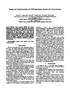
48KB flash ROM, JTAG emulation module, one hardware multiplier, three clock sources, and only consumes 2.0uA at 3V with 32.768 kHz clock running in Low Power Mode Level 3. The maximum working frequency of MSP430F1611 is 8MHz, but when low power consumption is major concern on wireless sensor node, the controller will never running in such high frequency. For compatibility to Tmote sky running TinyOS, the first version of Super Node also adopt the same RF transceiver as Tmote Sky, CC2420 from Texas Instrument shown in Fig. 2(a). The RF transceiver on final version of Super Node is UZ24008 U-stamp module from Uniband electronics corporation (UBEC). The u-stamp module with UZ2400 RF transceiver chip is fully complies with IEEE 802.15.4 PHY layer standard, working at 2.4 GHz unlicensed band, and has the ability to handle MAC layer packets. UZ2400 also has 128 bytes FIFO for TX and RX respectively, CSMA-CA controller, auto ACK response capability and a build-in AES-128 security encryption engine. UZ2400 can output a reference clock in four different frequencies, 2.5 MHz, 5 MHz, 10 MHz and 20 MHz, which can use as clock source for micro-controller. UZ2400 consumes 3.5 uA in standby mode, 22mA at 0dB TX mode, and 18mA at RX mode. Although MSP430F1611 has many functional pin, it is unnecessary to connect all them out. The connector pin configuration on Super Node is shown in Fig. 1.
Fig. 1. Connector pin layout on Super Node.
On Super Node, there is a 32.768 kHz crystal to generate RTC (real-time clock) and can be used as clock source for low power consumption in sleep interval. When in working mode, the default 2.5MHz clock signal is direct from the ustamp module as high speed baud rate clock. The eight channels of ADC on microcontroller are divided in two groups for two connector, and bother connector have serial communication ports, and two interruptible pins. The two connectors is located in two edges of the Super Node board, and the design is capable to stack more than one auxiliary boards for applications required more sensors or connecting auxiliary board of different functions. The photo of a Super Node board is showed in Figure 2(b).
-\ Ii it'
Fig. 2(a).Super Node with CC2420
(b) Super node with u-stamp. (32 x 29 mm, antenna excluded).
For outdoor long distance communication, u-stamp with external power amplifier (PA) can be used and can be fitted on the same Super Node board without any modification. The photo of the long range Super node is shown in Fig.3
Proc. of SPIE Vol. 6932 69323P-3
-
_y
Fig. 3. Super Node with external powerful PA u-stamp.
General version of Super Node can reach wireless communication distance over 30 m at -10dB power level. And the long range version with external PA can reach more than 100m and will find applications in outdoor field use. 3.2 Simple Node Simple Node use the same RF u-stamp module as Super node, but the micro-controller are replaced as C8051F4119 from Silicon Laboratories (Silabs). The microcontroller is an enhanced type 8051, and has many additional peripherals than a standard 8051, like Inter-Integrated Circuit (I2C), SPI serial communication port, twenty channels 12-bit ADC, two channels of current mode DAC, programmable counter/timer Array, two wire debugging interface, and 32 KB flash ROM. Beside those, it has a build-in 24.5MHz digital clock source and alternate 32.768 kHz RTC source. The RTC module inside the microcontroller can work even the 8051 core is fully off and used to waked up the microcontroller for power saving. So it is possible for Simple Node to become more power-saving then Super Node with this add-on feature. The RTC module alone consumes about 0.95uA, 8051 core that is configured in normal mode will consumes 17uA at 32 kHz and 13.5mA at 50MHz, and only consumes 0.15uA in suspend mode. When Simple Node enters low power state, microcontroller plus RFIC will only consume 0.95uA+0.15uA+3.5uA=4.6uA, which is smaller than Super Node (2.2uA+3.5uA=5.7uA). The reason to choose a 8051 derived microcontroller in simple node is for further single chip integration of RF transceiver and microcontroller, 8051 core is usually the best choice because of simplicity and intellectual property issues. The connector of Simple Node is very similar to P2 connector on Super Node, and the connection pins required for sensor auxiliary modules are completely identical. The detail pin connection layout is shown in Fig. 5.
C)
2 :V•JI
I. Fig. 4. Simple Node board. (28 x 17 mm, antenna excluded).
Fig. 5. The connector pin layout on Simple Node.
Simple Node has additional 16kbit EEPROM on board, which can be used to store extra data. The pin configuration of C8051F411 is programmable through crossbar, and user can modify the pin configuration for more ADC channels on pin 3 to 16. Because the 8051 core is using 2.5V supply (can be lowered to 2.1V), all ADC input level should be limited in the range smaller then 2.5V (or 2.1V). 3.3 Auxiliary Modules There are currently four auxiliary modules designed for Super Node and Simple Node. There are Super Node Programming Board, Super Node Battery Module, Simple Node Battery Module, and Accelerometer-Gyroscope module for Super Node.
Proc. of SPIE Vol. 6932 69323P-4
In order to let Programming Board have the ability to download TinyOS into Super Node, parts of the Boot Strap Loader (BSL) circuit are referred to the design of Tmote Sky. This board will supply 5V power source drawn from USB port to Super Node through a current limiting switch IC TPS2021 (Texas Instruments). The red LED on the Programming Board will light if the over current condition is triggered. This board has a MAX232 chip to handle voltage level conversion to RS232 serial port standard, and a PL2303HX (Prolific electronics), which is an USB to UART bridge for direction USB connection. Thus, Super Node can be connected to PC through RS232 or USB communication ports. The photo of Programming Board is showed in Fig. 6.
I.jli1 Fig. 6. Programming Board for Super Node.
For most WSN application, it is necessary to have a battery module powered the entire sensor node. Two kind of battery modules were designed for Super Nodes and for Simple Nodes respectively. Each battery module has a BQ24202 (Texas Instrument) Li-Ion battery charging and power management IC, and thus the battery module can be charged with simple USB port connection. The charging can be monitored through the LED light on the module. The battery on the board is 4.2V Li-Ion rechargeable batteries, and the capacity is depended on its size.
Fig. 7. (a)Battery Module for Super Node.
(b) Battery Module combined with Super Node.
The other module is accelerometer and gyroscope module, which is a showcase for design of sensor auxiliary board shown in Fig. 9. The module has a three axis accelerometer ADXL330 (Analog Device Inc (ADI) 10, and a two axis gyroscope form InvenSense11. This module have five analog outputs, two for x and y axis rotation, and three for x, y, and z acceleration. ADXL330 can measure acceleration ranging from -3.6g to 3.6g (g is Gravitational acceleration), with sensitivity about 300mA/g. This module was used in smart living space as elder fall detect, smart gallipot, and indoor localization. The last auxiliary board will be introduced is a Smart Sensor Interface Board. A Smart Sensor Interface Protocol (SSIP) is defined in-house for ease connection for different sensors. SSIP defines several important functions and enables the sensor auxiliary board to be a so called smart sensor. The smart sensor will have plug and play capability and the sensor nodes will recognize which kind of sensor boards were plugged in. Also, the smart sensor will have active power control capability which can minimize the power consumption and even continuous acquired data even the microcontroller in sensor board is off. The smart sensor will also have wake-up mechanism to actively wake up microcontroller on Super Node or Simple Node when specific monitoring condition is triggered. The photo of the Sensor Interface Board designed for Super Node is shown in Fig.10 which provides interface to three Smart Sensor Boards.
Proc. of SPIE Vol. 6932 69323P-5
Fig. 8. Accelerometer and Gyroscope module.
Fig. 9. Smart Sensor Interface Board
The concept of smart sensor will abstract the functions of sensors to a higher level and thus can separate the development efforts of network communication and sensors control and data collection into different level. In most case of WSN applications, different researchers from different fields will use the platform on different application deployment. Most of them may not have microcontroller programming experience. It will be the best solution to develop a base firmware perfuming the major functions of WSN such as data collecting and packet routing. Researchers can then control the behavior of sensors from higher level without reprogramming the microcontroller on the sensor node. Further smart sensor implementation and controlling software will be released soon in near future.
4. SOFTWARE RESOURCES There are three different levels to develop WSN application programs. The first is programming uz2400 and msp430 in register level. User can control every hardware functions, such as low level RF function control, ADC sampling, and power mode switching. The low level programming providing the complete control of entire hardware, however the programmer has to have hardware knowledge and have to develop the communication protocols by himself. This method is most powerful but too difficult for most researchers. The second way is to use an OS package, and the most popular one is TinyOS. There are many research institutions and universities using TinyOS for their research projects. Users can create simple programs base on example files of TinyOS, or just using the default program and Java-base GUI to gather data. Senior user can modify routing method inside TinyOS, add other functions or even port TinyOS to another platform. However, TinyOS has a fundamental drawback that is difficult to debug programs. TinyOS uses nesC complier to converts nesC code into mspgcc code, and cause the difficulty for user to debug the nesC code. Beside this, TinyOS development platform only runs on Linux or Cygwin (a Unix-like environment for Windows platform), and users will need some level of UNIX skills to setup the platform. The third way is commercial Zigbee stacks. For Chipcon series of IEEE 802.15.4 transceiver, Texas Instrument provides free z-stack Zigbee compliant protocol stack for users to build up their own WSN applications easily. For UZ2400, UBEC also provides a free UNET Zigbee like protocol stack. The source of UNET is even opening for educational and research use. No matter z-stack or UNET library, users still have to have C language programming capability, but the effort is not higher than programming using TinyOS. The following sections will illustrate how to using TinyOS and UNet on the Super Node and Simple Node platform. 4.1 Using TinyOS It is not so difficult to programming TinyOS into Super Node with the CC2420 transceiver. The only major hardware difference is the USB-to-serial bridge chip is different from Tmote sky. Thus, the BSL program will not search the com port automatically, users have to open device manager and check which com port was used by the USB to serial bridge (search the string: “Prolific USB-to-Serial Comm Port”). After the com port number is obtained, simply type in command window for “make telosb install bsl,” and then the com port name afterward, for this example: “com6”. Then TinyOS will then upload to Super Node through BSL program. After a few second, the successful loading messages will be shown as Fig. 12 screen dump.
Proc. of SPIE Vol. 6932 69323P-6
Wlt my lOS image
cx, huild/telosh/main ihex huild/telosh/rain ihex.out H
k—1
Fig. 10. Successful TinyOS loading message on Cygwin.
4.2 Using UNet Using UNet library in own applications is not so difficult. All parameters about packet routing controlling can be set in header files, and user only have to consider about how to response RF packets, when to acquire data form sensors, when to send out packets. Because those details about RF communication are packaged into several libraries file, when using UNet, users have to include those library files and header files into project for compiling. A sensor node can be programmed into a router or a coordinator role in UNet, they are corresponding to Zigbee router and coordinator. The end node mode is not yet completed and will be released soon in near future. UNet has been porting to different microcontroller platform like 8051 of Silabs, MSP430 of TI, and PIC of Microchip. User can program Super Node as router role which can do packet routing routine, or coordinator role (gateway) to collect the sensors data from the sensor network.
5. SMART LIVING SPACE OPEN LAB For smart living space application, the research team is teamed up with further researchers working on another project named “Development of a smart sustainable human-centric home” (S2H home) also funded by NSC Taiwan. There are three major axes in the S2H home projects. They are attentive home, which targeting on developing technologies to provide further level of comfort and convenience at home, medical home, which care about elders home care and remote medical care, and the final one is sustainable home, which targets on promote power-efficiency and alternate power source in typical household environment. WSN will play the technology backbone for the mentioned three parts, and will act as a neural system to provide sensing and control capability on the different parts of the living space. In order to facilitate and testing these new technologies and concepts, an “OpenLab” was built up in the campus of National Taiwan University. The OpenLab occupies about 53 square meter for presentation and conference space, about 33 square meter for general exhibition and about 109 square meter for smart home lab which is closed to a real home layout of typical Taiwanese families. The floor plan and some photos of the OpenLab are shown in Fib. 13.
Proc. of SPIE Vol. 6932 69323P-7
£ Fig. 11. Smart Living Space: The OpenLab.
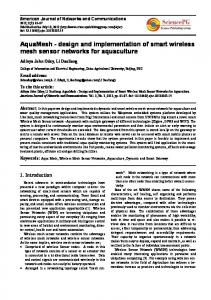
In order to build up the neural system of the living space, a complete WSN system with various sensors is built into the smart home lab. The floor plan of the smart home lab includes a living room, a dining room, a kitchen, a bathroom, two bedrooms and an indoor garden, and the sensors planned and built into the lab is shown in Fig. 14. There are also a home automation system controls the lighting, air conditioning system and major appliance which can link with the WSN system for fully interaction of the living space between user. The first stage of the lab setup including the major WSN system has been completed in the end of 2007. In the next stage, further team members will start to collect data from WSN and further establish the interaction model and also the human-machine interface to accomplish the three major axes in the lab.
fl •, . .• • ..p
emain bedroom bathroom
bedroom •
•
Light sensor
arden • C02 sensor
—-
living room
• Temperature sensor S Humidity sensor
•a
CO sensor
• IR sensor
dining roomkitchen•• :• • Reed switch
•
•
Accelerometer Gyroscope
Fig. 12. Sensors built in the OpenLab.
6. CONCLUSION In this paper, a newly design of low cost WSN platform is presented. With the modular concept, Super Node, Simple Node along with auxiliary modules can be assembled and fits for different application requirements. The smart sensor concept provides higher level control capabilities of sensor activities and simplified the difficulties of WSN programming. For smart living space application, a smart home lab was built up and with a complete WSN system as
Proc. of SPIE Vol. 6932 69323P-8
the neural system of the living space. Further system integration and service built up of smart living space incorporating the WSN system will be further conducted in near future.
REFERENCES [1] [2] [3] [4] [5]
[6] [7] [8] [9] [10] [11]
Lin, J.-L., H.-C. Liu, et al., “The development of wireless sensor network for ECG monitoring,” Proceedings of the 28th IEEE EMBS Annual International Conference 3513-3516 (2006). Ren-Guey, L., C. Kuei-Chien, et al., “A backup routing with wireless sensor network for bridge monitoring system,” Communication Networks and Services Research Conference 2006. Proceedings of the 4th Annual (2006). Lee, R.-G., C.-C. Lai, et al., “Design and implementation of a mobile-care system over wireless sensor network for home healthcare applications,” Proceedings of the 28th IEEE EMBS Annual International Conference (2006) Kohvakka, M., M. Hannikainen, et al., “Ultra low energy wireless temperature sensor network implementation. Personal, Indoor and Mobile Radio Communications,” PIMRC 2005. IEEE 16th International Symposium on (2005) Suhonen, J., M. Kohvakka, et al., “Design, implementation, and experiments on outdoor deployment of wireless sensor network for environmental monitoring,” SAMOS 2006 LNCS 4017, 109–121 (2006) TinyOS, http://www.tinyos.net/ Texas Instruments, http://www.ti.com/ Uniband Electronic Company, http://www.ubec.com.tw/ Silicon Laboratories, http://www.silabs.com/tgwWebApp/public/index.htm Analog Device, http://www.analog.com/en/ InvenSense, http://www.invensense.com/
Proc. of SPIE Vol. 6932 69323P-9