Design and Implementation of a Wireless Sensor Network applied to Motion Capture Helder D. Silva, Pedro Macedo, José A. Afonso
Luis A. Rocha
Department of Industrial Electronics University of Minho Guimarães, Portugal
[email protected]
School of Engineering University of Minho Guimarães, Portugal
Abstract— This paper describes the development of a wireless sensor network prototype and its application in a motion capture system based on inertial and magnetic sensors. The system presents a portable and modular architecture and allows the monitoring of several users at the same time using a single wireless network. The target application requires the wireless sensor network to operate efficiently under high loads, since it generates data intensive traffic and needs to support a high number of sensor modules. Other requirements imposed by the application are real-time operation and reliable data delivery. In order to provide the quality of service required by the application, an enhanced version of the LPRT medium access control protocol was developed and implemented in devices compliant with the IEEE 802.15.4 standard at the physical layer. Simulation results show that the proposed modifications improve the performance of the protocol. The implementation of the protocol is validated through the experimental results presented.
I.
INTRODUCTION
The range of application of motion capture systems spreads through several areas. In the healthcare sector, namely in physiotherapy, these systems can benefit both the patient, by increasing his levels of confidence, and the therapist, by providing detailed information about the patient’s evolution. The monitoring of athletes in sports such as athletics, gymnastics, golf, tennis and football, can provide detailed information in order to enhance the performance of both the athletes individually or teams as a whole. Other application areas of these systems are human-machine interfaces and character animation. The motion capture system described in this paper is based on a sensor module containing multiple inertial and magnetic sensors The processing of the instantaneous data acquired from this set of sensors allows the extraction of the orientation (roll, pitch and yaw angles) of the module in 3D space. When one of these sensor modules is attached to an object, its orientation can be obtained. Likewise, when several modules are attached to different segments of a user’s body, the movements of monitored parts can be tracked. Motion capture systems based on inertial sensors, such as this one, present the issue of how to send the data acquired from the multiple sensor modules to a receptor outside of the body. The connection of the modules to the receptor via cables
would restrict the mobility significantly. Some commercial systems use a hybrid approach where the sensor modules are connected through cables to a wireless transmitter, placed on the user’s body, which relays the data through a point-to-point link to the external receptor. Many of these systems are based on suits where the number and position of the sensor modules and the size of the suit are predefined. The system described in this paper, named Wireless Posture Monitoring System (WPMS), goes one step further, removing all cables through the implementation of wireless sensor modules. This portable and modular architecture increases the flexibility and versatility of the system, expanding the range of applications. The modules need only to be placed in the segments of the body that need to be monitored, which vary according to the application. For example, a physiotherapy session may need to use only one module in the upper leg and one in the lower leg to monitor the knee joint angle, whereas the measurement of the elbow joint angle would require two modules in the arm instead. On the other hand, the monitoring of a golf swing may require several sensor modules in the upper body. Another advantage of this system is that it can be used to monitor several users in the same area at the same time using a single wireless network. When compared to camera based motion capture systems, the main advantage of this system is that it can be used in uncontrolled environments, under any lighting conditions and without line of sight to the receptor. There are several challenges to the implementation of this system. To ensure unobtrusive utilization, the wireless sensor modules must be small and lightweight. Given that the modules need to be battery operated, the energy consumption, like in other WSN applications, is a concern, which means that it is desirable to use low power hardware and an energy efficient MAC (Medium Access Control) protocol. Typical motion capture file formats [1] define a hierarchy of up to 17 segments (bones) that can be monitored in a single body (skeleton). Even when fewer modules per body are used, maximization of the number of modules supported by the wireless network becomes desirable in order to allow monitoring of several users at the same time. Many applications, such as character animation, typically require a frame rate of 30 fps, which means that the sensors
have to be sampled at 30 Hz. Other applications may require even higher sampling rates in order to track fast movements. Moreover, each sensor module has multiple sensors, so the traffic generated by the modules is very intensive, in contrast with conventional WSN applications.
transmission of a beacon (B) by the base station. During the CAP (Contention Access Period), a CSMA/CA protocol similar to the one specified by the IEEE 802.15.4 standard is used to carry asynchronous traffic.
This data intensive traffic per module combined with the requirement to support a high number of modules means that the network has to operate under high loads. The contentionbased MAC protocols normally used in wireless sensor networks are not adequate in this scenario, since the high loads would lead to frequent collisions between the transmissions of the sensor modules. Other requirements of the application related to the quality of service (QoS) provided by the network are real-time operation and reliable data delivery. The monitoring of some types of biomedical signals is another application area with similar traffic characteristics and QoS requirements. As an example, the monitoring of ECG signals can require sampling rates of up to 250 Hz per lead with a resolution of 12 bits [2]. In order to benefit from low cost, due to economies of scale, and small size, due to component integration, it was decided to base the implementation in COTS (Commercial OffThe-Shelf) wireless network components. Currently, the two main low power wireless network technologies available in the market are Bluetooth [3] and IEEE 802.15.4 [4]. Given the requirements of the application stated above, the use of Bluetooth is not adequate due to the limitation of maximum seven slaves per piconet. The basic IEEE 802.15.4 MAC protocol is not suitable for this application, since it is a contention-based CSMA/CA (Carrier Sense Multiple Access with Collision Avoidance) scheme. This network also provides a Guaranteed Time Slot (GTS) mechanism in order to support devices requiring dedicated bandwidth and low latency transmission. However, this mechanism only allows seven GTS allocations per superframe, which is not enough to support the number of sensor modules required by the application. Given the limitations of these networks, we decided to implement a modified version of the LPRT MAC protocol [5] on top of a COTS device that is compliant with the IEEE 802.15.4 standard at the physical layer. LPRT is designed to provide bounded delay, maximize the throughput and energy efficiency and enhance the transmission reliability. This paper is organized as follows. Next section presents an overview of the LPRT MAC protocol and describes a proposed modification. Section III presents and discusses simulation results considering the application of the protocol in a motion capture scenario. Sections IV, V and VI present an overview of the Wireless Posture Monitoring System, a description of the software implementation and a set of experimental results, respectively. Finally, Section VII presents the conclusions. II.
MAC PROTOCOL
The LPRT (Low Power Real Time) [5] protocol is based in the superframe structure presented in Figure 1. Each superframe is divided in several mini-slots and starts with the
Figure 1: Superframe structure of the LPRT protocol.
The CFP (Contention Free Period) carries traffic scheduled by the base station and is composed by an optional Retransmission Period (RP) and a Normal Transmission Period (NTP). The NTP is used to transmit the data packets generated by the sensor nodes. The allocation of mini-slots for transmission in the NTP is requested during the association. The RP is composed by mini-slots reserved automatically by the base-station for retransmission of a data packet in a superframe when it was not delivered correctly in the NTP of the previous superframe. The payload of the beacon frame contains a superframe duration field, a list of Resource Grant (RG) fields and an ACK bitmap. Each RG is composed by a transmission direction (TD) bit; the Association ID (AID) field and an Initial Transmission Slot (ITS) field. The TD bit indicates the direction of the RG: downlink or uplink. The AID is a short address that is assigned to a node when it associates with the base station and replaces the larger MAC address. The ITS field indicates the position of the allocation in the superframe. For uplink transmissions the acknowledgment is made using the ACK bitmap in the next beacon, eliminating the bandwidth overhead associated with the reception of individual ACK frames for each uplink data packet. For downlink transmissions, a conventional ACK frame is used. The node’s transceiver need to be in the active state only during the reception of the beacon and the scheduled periods in the CFP, so the node can stay in the sleep state most of the time in order to save energy. Each time a node receives a beacon it resynchronizes its clock with the base station. In the LPRT protocol, when a node misses the beacon at the beginning of a superframe, it must not use its RGs in the CFP until it receives a beacon correctly. The GTS mechanism of the IEEE 802.15.4 presents a similar behavior. We propose a
III.
SIMULATION RESULTS
In order to evaluate the performance of the LPRT protocol and the proposed enhancements, a simulation model of the LPRT protocol was implemented using the version 4 of the OMNeT++ discrete-event simulation software. OMNeT++ is an open-source, modular, component-based C++ simulation library and framework [6][7]. The wireless network is based on a star topology. Each simulation ends after the base station receives 100,000 data packets from the sensor nodes. The sampling rate of the sensors nodes (fs) was set to 30 Hz, corresponding to a frame rate of 30 fps, which is a value typically used by motion capture applications. The superframe duration (TSF) was set to 100 ms, which means that each sensor generates 3 samples per superframe. The data packets are always transmitted in the same position in the superframe, so the jitter without retransmissions is zero. There are 6 sensors (3 accelerometers and 3 magnetometers) per node, which generate 12-bit samples. To save space, each two 12-bit samples are packed into 3 bytes. Each data packet also carries a sample of the battery voltage in 2 bytes. Therefore, the payload length required to carry all these samples is 29 bytes. For data packets, the MAC header occupies 9 bytes and includes the following fields: FCF (Frame Control Field), DSN (Data Sequence Number), PAN address, destination address, source AID and frame type. The MAC trailer is composed by a 2-byte FCS (Frame Check Sequence). The PHY header is the same used by the IEEE 802.15.4 radios and occupies 6 bytes. The length of data packets, considering the payload, the MAC overhead and the PHY overhead is 46 bytes. The RG field in the beacons of the LPRT protocol occupies 2 bytes and is composed by 1 bit for the transmission direction, 6 bits for the AID field and 9 bits for the ITS field. The 6 bits in the AID allows the support of up to 64 nodes in the CFP. The number of mini-slots per superframe (MSF) was set to 500, because with this value the period of each mini-slot, with the superframe duration of 100 ms, is 200 µs, which is an integer multiple of the resolution of the timer from the device that was used in the implementation (4 µs). The minimum duration of the CAP (CAPmin) was set to 11 ms, which is enough to allow the exchange of two full length frames, including the CSMA/CA backoff and the gap between the frames. The maximum duration of the CFP (CFPmax) is given by the superframe duration (TSF) minus a reserved period composed by the CAPmin plus the time required to transmit a
maximum length beacon (4.26 ms). Inside the CFP, besides the mini-slots required to accommodate the data packets, each transmission reserves an additional mini-slot to serve as guard time between the transmissions of the sensor nodes. Channel errors were modeled using the Gilbert-Elliot model [8], in order to take into account the occurrence of burst errors, which are typical in wireless channels. In this model, the channel alternates between a good state with low bit error rate (BERgood) and a bad state, with very high bit error rate (BERbad), with mean dwelling time Tgood for the good state and Tbad for the bad state. The choice of values for these parameters, presented in Table 1, is intended to model fast fading, which typically occurs on timescales of milliseconds to tens of milliseconds [9]. The channel errors for the different nodes were made symmetrical and independent, which means that at any moment the channel for some nodes can be in the bad state while for others it can be in the good state. Table 1: Parameters of the Gilbert-Elliot model. Parameter
Value
BERbad (sensor nodes to base station)
10-2
BERbad (base station to sensor nodes)
10-2/10-3 0
BERgood Tbad
5 ms
Tgood
95 ms
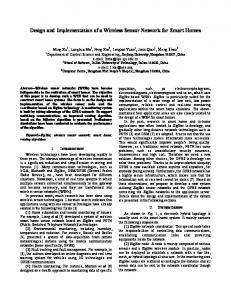
Figure 2 presents the delivery ratio as a function of the number of sensor nodes in the NTP, using the same value of BERbad (10-2) in both directions. With this value of BERbad, the probability of a beacon being corrupted by errors ranges from 80% to 99.9% depending on the size of the beacon (which increases with the number of sensor nodes), and the probability of a data packet being corrupted is 97.5%, which means that almost all successful transmissions occur only when the channel is in the good state. 1
0,98
0,96
Delivery Ratio
modification of the LPRT protocol that allows the use of the RGs in the NTP part of the CFP when the beacon is not received correctly. This modification works by the inclusion of a Rescheduling field in the beacon that normally takes the value zero (0). Whenever a rescheduling is necessary, this field is initially changed to the integer value Nres. During consecutive beacons, the value of this field is decremented until it reaches zero again. Starting from the beacon with the value Nres, the new values of the RG fields are announced in the beacon, replacing the old ones; however, the scheduling only changes effectively when the value of the Rescheduling field reaches zero. That means that the node can use the NTP even when it misses up to Nres consecutive beacons.
0,94
0,92
0,9
0,88 0
5
10
15
20
25
30
35
40
45
50
Number of Nodes LPRT without ret.
LPRT with ret.
Modified LPRT without ret.
Modified LPRT with ret.
Figure 2: Delivery ratio using the Gilbert-Elliot model with BERbad = 10-2.
Without retransmissions, the delivery ratio for the modified LPRT protocol is significantly better when compared with the original protocol, since in the former case it only depends on the successful reception of the data packet, where in the latter case (as well as in the GTS mechanism) it also requires previously the successful reception of the beacon of the
corresponding superframe. The delivery ratio for the modified LPRT protocol is also independent of the number of sensor nodes, while for the original LPRT it decreases slightly as the number of sensor nodes (and the size of the beacon) increase.
0,98 0,97
Delivery Ratio
The delivery ratio with retransmissions is significantly better then the observed without retransmission, for both protocols, especially with a medium number of nodes. As the number of nodes increases, approaching the capacity of the network, the NTP increases, so the space available for retransmissions decreases and the delivery ratio tends to the same value observed without retransmissions.
1 0,99
0,96 0,95 0,94 0,93 0,92 0,91 0
5
10
15
20
25
30
35
40
45
50
Number of Nodes
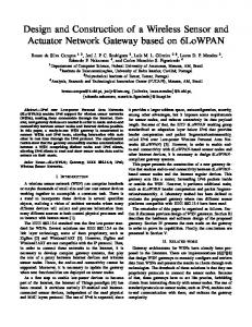
The delivery ratio with retransmissions for both protocols in the scenario of Figure 2 is worse when the number of nodes is small. The explanation is based on the fact that the scheduling of mini-slots for transmission of data messages starts from the end of the superframe and goes towards to its beginning, as the number of nodes increases, which means that the transmission of the first node is closely followed by the beacon of the next superframe. In a scenario with burst errors, the probability that the bad state observed during the transmission of this data packet extends into the reception of the beacon is high. When the beacon is corrupted, the node is unable to make the retransmissions, since it does not have the information about the allocation of mini-slots for retransmission. Therefore, burst errors tend to reduce the effectiveness of the retransmission mechanism for data packets that are scheduled for transmission close to the next beacon. As the number of nodes in the network increases, the average distance between the data transmissions and the following beacon also increases, decreasing the probability that the reception of the beacon is compromised by the bad state observed during the transmission of previous the data packet. Since the BER tends to decrease with the increase of the SNR (signal-to-noise ratio) [10], a solution to minimize this problem and improve the robustness the protocol consists in raising the output power of the base station transmitter, thus increasing the SNR for the beacon messages. This increment in the output power is not problematic in terms of energy consumption since, unlike the sensor nodes, the base station is not energy constrained. In the case of the system prototype described in the next section, the base station’s output power can be raised, up to +22 dBm, through the use of the CC2591 RF range extender [11]. Figure 3 presents the delivery ratio curves obtained in a scenario similar to the previous one. The only change is that the BERbad relative to the transmissions of the beacon is reduced to 10-3, to account for an increase in the base station output power, while the BERbad for the transmission of the data packets is the same (10-2). As the figure shows, the increment in the probability of reception of the beacon increases the overall delivery ratio with retransmissions in both cases, with particular incidence when the number of nodes is small. As shown in the simulation results, the LPRT protocol supports 46 sensor nodes with the traffic parameters considered in this section, which is significantly more than the 7 nodes supported by the GTS mechanism.
LPRT without ret.
LPRTwith ret.
Modified LPRT without ret.
Modified LPRT with ret.
Figure 3: Delivery ratio with BERbad = 10-2 (data) and 10-3 (beacon).
The maximum additional delay of the data packets due to the retransmissions is equal to the superframe duration. An increase in the superframe duration would tend to increase the number of supported nodes and decrease the energy consumption, since the payload length would increase, reducing the protocol overhead. However, the maximum delay would also increase. IV.
SYSTEM OVERVIEW
The Wireless Posture Monitoring System is composed of three main components: the PC, the base station and the multiple sensor nodes that collect movement data, as represented in Figure 4.
Figure 4: System overview.
The PC executes an application which allows the interaction with the user, enabling the configuration of several system parameters, such as the duration of the network superframe, the number of samples each sensor node shall acquire per superframe, the number of persons being monitored and the association of each sensor with a person’s body segment. The application’s main window, shown in Figure 5, allows parameter configuration and displays several information relative to the wireless sensor network, such as delivery error ratio, number of nodes, network occupation and signal strength from the packets received.
Figure 7: Base station architecture.
The base station cannot be switched off in order to conserve energy, due to its role of coordinator. However, since this device is powered by an external power supply, such as a PC, energy saving is not a primal concern, as opposed to the sensor nodes.
Figure 5: Main application window.
The PC application receives the data acquired from the sensor nodes, calculates the angles of the segments of the user’s body, generates a 3D model (Figure 6) compliant with the BVH (Biovision Hierarchy) file format [1] and displays the movement of the user’s body in real-time.
B. Sensor node architecture The sensor nodes collect posture data from each body segment of a person. Each node is equipped with a group of six sensors, three accelerometers and three magnetometers, which capture variations in the x, y and z axis. These sensor variations reflect gravitational and magnetic field force variations, allowing the calculation of the orientation of the segment that is being monitored. The sensor node architecture is illustrated in Figure 8.
Figure 8: Sensor node architecture.
Figure 6: Application's 3D model.
The application also provides a window for calibration of the sensor nodes. The calibration affects the magnetic sensors and consists in determining the minimum and maximum values that can be read, in order to compute its orientation relative to the main body segment (hip). A sensor node prototype was also implemented. It is described in the section C. A. Base station architecture The base station performs the role of network coordinator, being therefore responsible for maintaining information regarding sensor nodes associated with the network, allocations assigned to each sensor node, as well as defining the temporal structure of the superframe. The architecture of the base station is presented in Figure 7. It receives packets from sensor nodes through the radio interface and forwards them through the serial connection to the PC application.
The sensors are sampled at a frequency configured by the application. Each sensor is sampled through an ADC channel, and can be turned on/off through a control interface. The nodes sample each of its sensors periodically, aggregate sets of samples in packets and send them to the base station using the radio interface. These packets are then forwarded from the base station to the PC application. With this information, the application can calculate the roll, pitch and yaw angles for each body segment of a person, obtaining the posture of the body. Since the sensor nodes are powered by batteries, the hardware enters the sleep state whenever possible, in order to save energy. The radio interface is compatible with IEEE 802.15.4 standard. C. Sensor node prototype Regarding the sensor nodes, the printed circuit board displayed in Figure 9 was developed for the sensor node prototype. The main component of the sensor node is the CC2430 [12], from Texas Instruments, a SoC (System on Chip) that integrates an 8051 based microcontroller and an IEEE 802.15.4 compliant transceiver in the same chip. The prototype
integrates also a three-axis accelerometer and two magnetometers of one and two axis respectively. Fifth order low pass elliptical filters were used to minimize noise from sensor readings. A DAC (Digital-to-Analog Converter) with adjustable current enables calibration of the magnetic sensors, which are sensitive to magnetic field variations. A printed circuit antenna compatible with CC2430 radio was also implemented [13], effectively reducing the size of the sensor node and making it less obtrusive.
Figure 11: System software modules and their relation to LPRT.
Two types of medium access were implemented: direct and CSMA access. The direct mode transmits the packet immediately and without CCA verification (this mode is used in TDMA accesses) while the CSMA access runs the CSMA/CA algorithm before accessing the medium. The latter is also subject to a time limit, so the sensor nodes do not try to access the channel during the CAP if it is not possible to end the transmission before the beginning of the CFP. Figure 9: Sensor node hardware prototype.
V.
SOFTWARE IMPLEMENTATION
Figure 10 presents an overview of the communication layers present in the Wireless Posture Monitoring System. The 802.15.4 physical layer is totally implemented by the radio hardware. The LPRT protocol controls the communication between the base station and the sensor nodes through the wireless medium while the WPMS application handles the exchange of messages between the PC and the sensor nodes.
The Timer MAC module generates time intervals required by the Radio module. This is a 16-bit timer with adjustable period and is used to execute the backoff periods and to manage the timeout for the reception of the acknowledgment frame in messages sent with the acknowledgment request active. The Sleep Timer’s main function is to generate time intervals between events, during which the radio and microprocessor can be turned off in order to save energy. It is a 24-bit timer that uses a crystal oscillator as time source, counting uninterruptedly after a system reset. A total of four power modes are available: power mode 0 is the active mode, while power modes 1, 2 and 3 are sleep modes where energy consumption is reduced to 190 µA, 0.5 µA and 0.3 µA respectively. The whole RAM memory is available during power modes 0 and 1, while only 4 KB are available in the remaining power modes. Power mode 1 was chosen to be used when the CC2430 is turned off because, when compared to the other sleep modes, the difference in overall sensor node’s energy consumption is small, since a major part of the consumption is due to the sensors and respective filter circuitry.
Figure 10: Communication layers for each system device.
Figure 11 presents a generic diagram of the relation between the software modules used to control the hardware and the software modules that implement the LPRT protocol and the serial port communications. The SerialCom and related modules are only implemented in the base station, while the ADC module is only implemented in the sensor node. The Radio module has a central role in communications between devices, since it controls transmission and reception of data packets using IEEE 802.15.4. Hardware interruptions are controlled whenever a packet is received or transmitted. During packet reception, this module acknowledges messages automatically whenever requested.
Timer 1 is a 16-bit timer with three independent channels. Its operating frequency is derived from the main system clock (32 Mhz) and can be divided by 8, 32 or 128. This module is used in the LPRT implementation to generate time intervals associated to the protocol, such as the superframe period and the duration of the access periods, as well as to account for time elapsed between events. Among the 8-bit timers available in CC2430, only timer 3 was used. This timer is used in the serial communications to control time intervals between transmission and reception of acknowledgment messages. The UART 0 module controls the configurations regarding the serial port communications, namely the baud rate, number of data bits, number of stop bits and parity. It is important to
note that the baud rate of the UART should be equal or greater than the data rate of the radio interface (250 kbps), so the serial port does not become a “bottleneck”. For this reason, the baud rate chosen was 460800 Bd. The SerialCom module builds its functionalities on top of the UART 0 module and allows full duplex communication in the serial connection. The PC and the base station communicate using a simple stop-and-wait type protocol. Messages are classified according to two levels of importance: normal or critical. Normal messages do not require acknowledgments, while critical messages do. In case of transmission failure, the upper levels decide whether or not to retransmit the respective undelivered messages. A. Protocol Implementation 1) Base station Besides implementing the time structure defined in the superframe, the base station implementation revolves around two main aspects: the sensor nodes associated with the network and the respective allocations requested. A sensor node is represented by a set of variables containing a short address, an AID and the assigned allocations. Each allocation is represented by another set of variables which indicate the number of slots used, the ITS allocated, the sensor node owner of allocation, the number of consecutive messages not received, the transmission direction and the type of allocation (NTP or RP). Figure 12 shows an example of the time structure implemented by the base station.
Figure 12: Superframe timing example.
All downlink allocations appear before any RP or NTP allocations in the current implementation. This does not affect the LPRT performance and simplifies both the base station and the sensor node implementations, since they do not have to switch the radio between transmission and reception states more often in such a superframe. 2) Sensor Node The implementation of the protocol at the sensor node uses the operating principle of a discrete-event system at its basis. The sensor node can have more than one allocation in a superframe and it can also access the medium using the CAP. The model describes the actions to be executed through a list of events, chronologically ordered. Besides respecting the superframe structure of the base station, the implementation
accounts for all the allocations assigned to the sensor node and the respective events to be executed in each superframe. Events are represented by a set of variables indicating the type of event, periodicity, duration and exact instant of time inside of the superframe when it is scheduled for execution. An allocation is represented by the number of mini-slots it possesses, its position in the beacon message and the acknowledgment indication of the last beacon received. The last message transmitted for each allocation slot is also saved for each superframe, so these messages can be retransmitted in case the respective acknowledgment bit indicates a message not received. B. Application The sensor node receives the indication of the number of samples during the association process. This number is used, together with the superframe duration, to calculate the time interval between samples before the immediate transmission of the data in the respective allocation slot of the MAC layer. Regarding the functionality of the PC application, a set of commands were created to allow configuration and retrieval of information stored by the base station through the UART interface. There are commands to start/stop network operation, configure the number of samples, change superframe duration, send downlink messages (used to send calibration messages to sensor nodes) and retrieve information about a sensor node. VI.
EXPERIMENTAL RESULTS
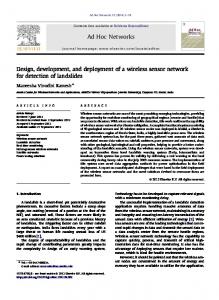
In order to validate the implementation of the MAC protocol, a test tool was created. This tool, which runs in a separate CC2430 module connected to a PC, collects received signal strength indicator (RSSI) samples at the selected channel continuously, every 128 µs, by reading the RSSI register of the radio transceiver. The value of the CCA bit from the radio is also collected, along with the first byte of the sleep timer counter, which represents the axis of time. These values are sent through the serial connection to a PC application. The PC gathers all values received and plots a graph with the RSSI and CCA values as a function of time. Figure 13 shows the values obtained for the association process of a sensor node with the base station. After the transmission of the beacon by the base station, the sensor node starts the association process with the coordinator. The time gap between the first beacon and the transmission of the association request corresponds to the processing time of the beacon by the sensor node and the random CSMA/CA backoff time to access the medium. After the association response is received by the sensor node, it enters sleep mode for the remaining duration of the superframe. Once the association is concluded, the sensor node transmits the calibration vector during the next CAP, and starts sending periodic messages in the allocated NTP slot. Figure 14 shows the output of the RSSI and CCA test for a superframe with four allocations in the NTP. As shown in the figure, in order to assure that the base station has sufficient time to process all allocations prior to transmitting the next beacon frame, the beacon transmission
was delayed by 3 ms in the current implementation. The sensor node is aware of this delay from the start of the superframe when a beacon is received.
Figure 13: Association of a sensor node.
VII. CONCLUSIONS This paper describes the design and implementation of a wireless sensor network prototype based on the CC2430 integrated circuit. The prototype is based in the 2.4 GHz physical layer of the IEEE 802.15.4 protocol and implements an enhanced version of the LPRT MAC protocol that increases the delivery ratio in comparison to both the original protocol and the GTS mechanism of the IEEE 802.15.4. Other advantages of the LPRT protocol with relation to the GTS mechanism are: support for more than 7 nodes (up to 46 in the application scenario); fine grained allocation of transmission periods to avoid waste of bandwidth; piggybacking of the ACK feedback in beacon frames to decrease the protocol overhead; and automatic scheduling of collision-free retransmissions to increase the delivery ratio. These advantages tend to increase the bandwidth efficiency. Future work includes the execution of further experimental tests to evaluate the performance of the developed prototype and the proposal, implementation and test of new enhancements to the prototype and the LPRT protocol. ACKNOWLEDGMENT This work is supported by the Portuguese Foundation for Science and Technology (FCT), through the project PTDC/EEA-TEL/68625/2006. REFERENCES [1] [2]
Figure 14: Transmission in NTP by 4 sensor nodes. [3]
Figure 15 exemplifies the retransmission mechanism of LPRT. The sensor node does not transmit its message on purpose in the first superframe, so the base station assigns a new RP allocation automatically. The message is then retransmitted in the next superframe, prior to the transmission of the new data message for the respective superframe.
[4]
[5]
[6]
[7] [8]
[9]
[10]
[11] Figure 15: Retransmission mechanism. [12] [13]
J. Lander, “Working with Motion Capture File Formats”, Game Developer Magazine, pp. 30-37, January 1998. M. Paksuniemi, H. Sorvoja, E. Alasaarela, and R. Myllylä, “Wireless Sensor and Data Transmission Needs and Technologies for Patient Monitoring in the Operating Room and Intensive Care Unit”, IEEE EMBC 2005, Shanghai, China, September 2005. Bluetooth SIG, “Specification of the Bluetooth system”, November 2003. Retrieved from http://www.bluetooth.org. IEEE Std 802.15.4-2006, Part 15.4: Wireless Medium Access Control (MAC) and Physical Layer (PHY) Specifications for Low-Rate Wireless Personal Area Networks (WPANs), September 2006. “MAC Protocol for Low-Power Real-Time Wireless Sensing and Actuation”, IEEE International Conference on Electronics, Circuits and Systems (ICECS2006), Nice, France, December 2006. A. Varga, “The OMNeT++ Discrete Event Simulation System” European Simulation Multiconference (ESM 2001), Prague, Czech Republic, June 2001. OMNeT++ Community Site. http://www.omnetpp.org. J. Ebert and A. Willig, “A Gilbert-Elliot Bit Error Model and the Efficient Use in Packet Level Simulation”, TKN Technical Report TKN99-002, March 1999. A. Willig, “Recent and Emerging Topics in Wireless Industrial Communications: A Selection”, IEEE Transactions in Industrial Informatics, Vol. 4, No. 2, May 2008. M. Zuniga and B. Krishnamachari , “Analyzing the Transitional Region in Low Power Wireless Links”, 1st IEEE Annual Conference on Sensor and Ad Hoc Communications and Networks (SECON 2004), pp. 517526, Santa Clara, CA, October 2004. E. Slette and M. Paszowski, “Using CC2591 Front End with CC2530/1”, Application Note AN086, Texas Instruments. Retrieved from http://www.ti.com Texas Instruments, “CC2430 Data Sheet (rev. 2.1)”, 2007. Retrieved from http://www.ti.com. A. Andersen, “Small Size 2.4 GHz PCB antenna”, Application Note AN043, Texas Instruments, 2008. Retrieved from http://www.ti.com.