Pr oc e e di ngsof I NTERNATI ONALCONFERENCEON SYSTEMSENGI NEERI NGANDEMERGI NGSYSTEMS I CSEES‘ 14
23-25J anuar y , 2014 Or gani z e dby
1951
PSGCo l l e g eo fTe c h n o l o g y Co i mb a t o r e-6 4 10 0 4
I nCo l l a b o r a t i o nwi t h
Uni ve r s i t yofSout hAus t r a l i a
Comput e rSoc i e t yofI ndi a
MESSAGE
PRINCIPAL PSG College of Technology It is my great honour and distinct pleasure to welcome all to the International Conference on Systems Engineering and Emerging Systems brought jointly by PSG College of Technology and University of South Australia. I welcome and encourage efforts by both PSG College of Technology and University of South Australia to work towards meeting the common goal of spreading awareness of importance and knowledge of Systems Engineering and Emerging Systems. I believe this is a right step at the right time to instil the thirst for Systems Engineering knowledge and to quench the thirst through various sessions and lectures during the course of these three days. I wish the best for organizers, delegates and all involved in realizing this International Conference. May our quest of excellence continue and bring the fruits of such efforts to be shared by society!
Dr. R. Rudramoorthy
PREFACE
Complex problems face our world today. Finding smart solutions to such problems is possible only through interaction of good researchers and problem solvers. The International Conference on Systems Engineering and Emerging systems (ICSEES 2014) provides a forum for researchers to share their experience and research findings. The conference proceedings contains the papers accepted to the International Conference on Systems Engineering and Emerging systems (ICSEES 2014). The conference paperspresented in this conference will help address the complex challenges, and strategies for solving such challenges. Such discussions in this forum will help scientists, researchers, engineers attending this conference. The editors would like to thank the authors for their contribution and reviewers for their support.
Organizing Team ICSEES14
Contents Preface Minimum Partial Euclidean Distance based K Best Algorithm
1
Using Wavelet Modulation for High Performance MIMO BALAKRISHNAN C, POORNIMA R
Archit Synchronism of NC-OFDM in Dynamic Spectrum
12
Management of Cognitive Radio Harinessha.K
Automatic Health Monitoring System Using ARM9 Processor
18
Prabakaran. C.R, Suryaprakash. R, Vijayakumar. P, Bhagyalakshmi. M
Wireless Power Transfer System
24
Senthil Nathan. M, Pandiarajan. K Design and Development of 12 – Lead Portable ECG System using Programmable System on Chip
29
Ch Ramesh Babu, PV Hema Latha, V Divya Vani Roadsters Sense and Lanes Side Tree Shadow Amputation in
34
Satellite Images J. Rajalakshmi, C. Ram Niranchan. Assessment of Load Frequency Variations of Wind Diesel Hybrid Power System Using GA and Bacterial Foraging Algorithm
38
P.Dhanalakshmi, J.Booma, K.Mahadevan MDO Centric Verification & Validation Sala Lakshmanan, P R Baghel
43
Conceptual abstraction of high technology defense systems using Systems engineering principles
50
Ajith Kumar.K, Dr Jagathyraj V.P Software Version Control and Base Line Management of Airborne Systems
55
Y. Maheshwaran, Dr. S Christopher A Review of Finite Element Method in Selective Laser Sintering (SLS) Process
61
Rajkumar Velu, Sarat Singamneni Multiscale and Multilevel Curvelet Analysis of Mammogram using Complex Neural Network
69
E.Malar, Dr. A.Kandaswamy Development of an Embedded Sleep APNEA Detector using Electrocardiograph Signals for In-home Applications: Technical Perspective
73
Banu Rekha B, Kandaswamy. A, Vinodini S Design and Implementation of a Wireless Sensor Network using PICmicro and ZigBee S. G. Shiva Prasad Yadav, Sanket Dessai
78
MINIMUM PARTIAL EUCLIDEAN DISTANCE BASED K BEST ALGORITHM USING WAVELET MODULATION FOR HIGH PERFORMANCE MIMO DETECTOR BALAKRISHNAN C1, POORNIMA R2
Output (MIMO) system. Finally the scatter plot is compared for
Abstract-In order to solve the trade-off between computation
both Fast Fourier Transform (FFT) and Wavelet Packet complexity and improved Bit-error rate (BER); and also to
Transform (WPT). The calculation for wavelet based SNR vs.
increase the receiver sensitivity in high signal-to noise (SNR)
BER shows the less amount of bit error involved in signal
ratio environment, Minimum Partial Euclidean Distance (PED)
compared to Fast Fourier Transform (FFT) based scheme.
based K-best algorithm using wavelet modulation is proposed in this paper. It is based on breath- first search methods. The
Index Terms- Complex-domain detection, K-best detectors,
proposed design is independent of the constellation size, number
PED, FFT, wavelet modulation, Multiple Input Multiple Output
of transmit and receive antennas. The minimum PED based K-
detector.
best detector guarantees a Signal to Noise Ratio (SNR)-
I.
INTRODUCTION
independent fixed throughput with a performance close to
MIMO systems today are considered to be a great challenging research area in the telecommunication. It is said to be one of the solutions for solving the bottlenecks of traffic capacity in the forthcoming broadband wireless internet access networks and to give high performance.
Maximum Likelihood Detection (MLD) method and constant Bit Error Rate (BER) with irrespective of constellations. The main innovations are the nodes are expanded and visited based on minimum PED rather than exhaustively, as well as it keep track of symbols selected at each cycle. Being fixed-throughput in
The designing of a low-complexity, low-energy, less-BER, high-performance, and high-throughput receivers is the key challenge in MIMO receiver. Among several MIMO detection algorithms Maximum-Likelihood (ML) detection method is the optimal and minimizes the bit error rate (BER). But its computational complexity grows exponentially with constellation size and number of transmit antennas [1]. The potential of MIMO systems is to design a low-complexity high-throughput detection schemes with near MaximumLikelihood (ML) performance [2] that is suitable for efficient Very Large Scale Integration (VLSI) realization. On the other hand, linear detection algorithms such as the Zero-Forcing (ZF), Minimum Mean-Square Error (MMSE) or Successive Interference Cancellation (SIC) detectors [3] can greatly reduce the computational complexity, at the same time they have reduced performance. Finally, to solve the tradeoff between complexity and performance loss, a large category of receiver detection algorithm has been proposed, which includes the depth-first and the breadth-first search algorithms. The most popular
nature along with the fact that the breadth-first approaches are feed-forward detection schemes makes them especially attractive one for VLSI implementation. The simulation is carried out in different stages, in this paper the number of transmit and receive antennas is chosen as 2 and 64 constellations QAM is chosen. The input message signal is Quadrature Amplitude Modulation (QAM) modulated, and then the output complex domain is converted to wavelet signals. The packets are made suitable to the MIMO system. Then the signal is transmitted using Additive White Gaussian Noise (AWGN) channel. Then the received symbols from MIMO receiver is detected using the minimum PED based K-best algorithm, Moreover, the algorithm builds a tree with the children’s and identify the best child with minimum PED, the selected child act as an parent node for next cycle and the cycle is repeated until all such children’s in a tree are visited. Finally it provides the exact best node solution, i.e., the minimum PED node for the received signal in Multiple Input Multiple
1
among depth-first strategy is the sphere decoder (SD) [4], which guarantees the optimal performance in case of unlimited execution time [5]. But the throughput results in extra over head in the hardware and significantly lower data rates in the lower signal-to-noise ratio (SNR). Among the breadth-first search methods, the most well-known approach is the K-best algorithm, [6]. The K-best detection algorithm method guarantees a SNR-independent fixed-throughput with a performance close to ML. Being fixed-throughput in nature along with the fact that the breadth-first approaches are feedforward detection schemes, makes them especially attractive one for VLSI implementation. Also some efforts are made towards their implementation in VLSI design [4], [7].
In order to achieve the diversity technology, the spatial multiplexing is been commonly used to increase the capacity of Multiple-Input-Multiple-Output (MIMO) communication [11], by transmitting the independent message in the same time slot and frequency band simultaneously from individual transmit antennas, and separation of multiple data streams at the receiver using channel information of each path of propagation, Fig. 1 shows the principal of spatial multiplexing, exploiting the spatial dimension of radio channel which allows to transmit different data streams simultaneously.
In each cycle, K (Parent of node) × M (child of node) children should be enumerated, which result in large computation complexity in K-Best algorithm. The basecentric search methodology [8], and the relaxed K-Best enumeration [9] are compared [2]. These schemes do not linearly scale with the constellation size when applied to the complex domain and has performance loss compared to exact K-Best algorithm scheme. The on-demand expansion scheme reduces the computational complexity and independent of constellation size [1], on the other hand the minimum Partial Euclidean Distance (PED) based has better improved performance than the on-demand expansion scheme.
Fig. 1. Spatial multiplexing of MIMO In contrast to the spatial multiplexing or spatial diversity the other physical layer technologies like Orthogonal Frequency Division Multiplexing and time diversity technology are used for spectral efficiency and reduced complexity but these technologies suffer from reduced capacity link.
For 16-QAM, K is chosen to be 4 while for 64-QAM, K=8 meaning that the constellation quadruples but the K value only doubles, thus the increased sub-linear. It also has fixed critical path delay independent of the constellation, K value, and the number of antennas used. Moreover, it efficiently expands a very small fraction of all possible children in the K-best algorithm and it can be applied to an infinite lattices. II.
The mobile devices use the frequency band, which is strictly restricted by its limited bandwidth. The reliability of the communication is achieved with maximum data rate and constant bit error rate (BER) for varying signal-to-noise ratio (SNR), this is achieved with Multiple Input, Multiple Output (MIMO) system. The MIMO wireless technology can be any one of the following.
MIMO TECHNOLOGY A. MIMO-SISO One of the simplest designs of the radio link can be established in MIMO design using the Single Input Single Output (SISO). The system is an effectively a standard radio channel with single transmit and receive antenna, in this mechanism transmitter operates with one antenna as does the receiver. In MIMO-SISO system there is no need of diversity techniques and no additional processing is required. The Fig. 2 shows the MIMO-SISO based system.
The MIMO technology uses the advantage of radio-wave phenomena called the multipath, where transmission signal bounces at different angle at different times, the MIMO overcomes the multipath behavior by using multiple, transmitters and receivers by adding the „spatial‟ dimension to increase the performance and flexibility. As the result of using multiple antennas the channel capacity and throughput get increased. In MIMO environment the signal is propagating from the transmitter to the receiver along number of different paths, collectively referred as multipath. While propagating the signal power drops of due to three effects: path loss, macroscopic fading and microscopic fading. Fading of the signal can be reduced by different diversity techniques.
Fig. 2. MIMO-SISO
2
B. MIMO-SIMO One of the versions of MIMO technology is Single Input Multiple Output (SIMO), in which the transmitter has a single antenna and the receiver has a multiple antennas. This is often called as receive diversity, which enables the receiver system to receive the signal from number of independent sources to combat the effects of the fading, Fig. 3 shows the MIMOSIMO version. The drawback is, it requires complex detection algorithm at the receiver side.
equivalent baseband between the transmitter and receiver is described in a complex-valued Nr×Nt channel matrix H. The complex-valued base band received signal is expressed as. Y=Hx+e
Where x =[x1, x2, ...., xNt]T is the Nt- dimensional complex transmit signal vector, where each element is independently obtain from the complex constellation of QAM, Y=[Y1,Y2, ...., YNr]T is the Nr dimensional symbol vector of received signal, e=[e1, e2, ...., eNr]T is a complex-zero mean Gaussian noise with the variance of σ2 per dimension. In this paper we consider the complex domain frame work; on the other hand the real value decomposition can also be derived for the received signal [4].
Fig. 3. MIMO-SIMO
The ultimate goal is to find the closest lattice point x for the received signal vector Y.
Switched diversity SIMO, model looks for the strongest signal and switches the antenna.
ẍ= arg min ||Y-Hx||2 x€ONt
Maximum ratio combining SIMO, model takes the both the received signal in a receiver antenna and sums the received signal in both received antennas to give the combination of both the signals.
(2)
where O is the set of vectors from the real entries in the constellation, e.g., O={-3, -1, 1, 3} in case of 16-QAM. In this work Minimum Partial Euclidean distance (PED) based KBest algorithm is used to solve the above problem in the complex domain with reduced computational complexity. Since the algorithm is based on the K-Best algorithm, first it is described in detail as follows.
C. MIMO-MISO Multiple Input Single Output (MISO) is also known as transmit diversity, the Fig. 4 shows the MIMO-MISO. In the transmit diversity technique, the same data is transmitted repeatedly from the transmitting side through the transmitting antennas. The receiver is then able to receive the optimal signal, which it can be used to extract required transmitting message bits.
IV.
K-BEST DETECTION SCHEME
The breadth-first search method can also be implemented in Multiple-Input-Multiple-Output (MIMO) detection scheme, one of the common and well known approaches of breadth – first scheme is K-Best detection algorithm. The breadth-first algorithm searches for the best candidate node in forward direction only, but the best K node candidate is available at each level of sublatice. Hence, the breadth-first algorithms result in the constant decoding throughput, the K should keep as large as possible, compared with exhaustive-search Maximum Likelihood (ML) algorithm. The BER performance is close to the ML detection scheme.
Fig. 4. MIMO-MISO The advantage of using the MISO system is that the multiple antennas and the redundancy coding or processing is moved from the receiver to the transmitter. III.
(1)
The channel matrix H is QR decomposed as H=QR, where Q is the unitary Nr×Nt matrix and R is the upper triangular Nt×Nt matrix. By taking hermetian of Q or (QH), the nulling operation can be performed, which results in Z=QH×Y, which inturn equals to Rx+w, where w=QH+e, the nulling matrix is always known to be one, where the noise w after nulling
MIMO SYSTEM MODEL
Assume the MIMO system with Nt transmits and Nr receive antennas. For the Rayleigh fading channel the
3
remains spatially white. Since R is an upper triangular in nature, hence the equation (2) can be represented as Nt
challenges and works well for any values of K and M without any performance loss.
Nt
ẍ= arg min ∑ |zi- ∑ | rij ej |2 j=i x€ONt i=1
(3)
The MIMO detection algorithms have many challenges to implement them in the complex domain. The most of the MIMO detection algorithm address the problem in the real domain, to address the challenges in the complex domain the minimum PED based K-Best algorithm is proposed in this paper, which is independent of the constellation size, high performance and constant bit-error rate (BER) for varying signal-to-noise ratio (SNR).
we can consider the equation (3) as an tree- search problem with Nt levels, where, starting from the last row, one symbol is detected and, based on that, the next symbol in the upper row is detected, and so on. Thus starting from i=Nt the symbols are detected in K-Best algorithm in the iterative manner. The K-Best algorithm expands the individual K existing nodes at each level to produce M new possible children, from the given constellation size and calculates their updated Partial Euclidean Distance (PED). The result is that it produces KM nodes by sorting mechanism and then selects the K best nodes based on the lowest PED as the surviving node in the next level. The hard decision output of the detector is chosen as the path with lowest level of the PED at the first level. There are two computing procedures in the K-Best algorithm, which is discussed as follows.
The steps in the K-Best algorithm are described as follows. Step 1) Initialize one path of the root node with the PED value of zero. Step 2) Extend each node, retained from the previous level and update the accumulated metric of each path. Step 3) Sort the paths according to the accumulated metrics and select the K-best path. Step 4) Update the path history for each sorted path at the levels and discard the other paths. Step 5) If the iteration arrives at the end sublatice then the algorithm is stopped; otherwise the algorithm is repeated from the (step 2).
1) Expansion: The K-Best algorithm in the complex domain can be expressed of K (parents of each level) ×M (Children per parent) children should be computed, which results in larger computational complexity. The base-centric search methodology [8] and relaxed K-Best algorithm based on QPSK modulation [9] are compared [2]. These schemes do not scale linearly with the constellation size even though it can be applied to the complex domain, and it has got the performance loss compared to the exact K-Best algorithm. In the on demand expansion scheme the nodes are expanded by considering all the nodes PED, which in turn reduces the performance for higher order constellations. To overcome the above two challenges in this paper the minimum PED based K-Best algorithm is proposed, which consider the node with the minimum PED as the parent node at each level. The computational complexity and performance will be better than the on-demand expansion scheme.
The best part of the last iteration in the K-Best algorithm is, thus the hard decision output of the decoder, since the K-Best algorithm has a fixed throughput it can be easily implemented in the parallel and in pipelined manner. PROPOSED MINIMUM PED K-BEST ALGORITHM The implementation of various detection algorithms in the real domain is much simpler than to implement in the complex domain, as in the real domain it is straight forward to implement as the next child can be sorted based on the zigzag movement around the unconstrained received value without any Partial Euclidean Distance (PED). V.
2) Sorting: KM children should be sorted in each level of the complex-domain in the K-Best algorithm. In [10] and [13], most of the sorting schemes such as bubble sorting [6], (sorting mechanism on the basis of Schnorr-Euchner (SE) ( [3], [12]) technique) and a distributed sorting schemes are compared. But these techniques take high time for large values of the K and M or it will be having a performance loss. To address this challenge the minimum PED based algorithm is implemented in this paper which overcomes all this
The proposed minimum PED K-Best algorithm is based on the breadth-first tree search method. The algorithm is initialized by considering the level Ɩ of the trees and assumes the candidate nodes in the level Ɩ+1 is known in the tree. The individual nodes in the level KƖ+1 will be having √M possible children‟s and the number of cycles or K value also will be based on the square root of constellation order, so there will be √K×√M possible children in the tree. The one of the main objective of the proposed scheme is to find the first best child (FBC) of the initial parent node, based on the minimum
4
Partial Euclidean Distance (PED) of the received first √M children of the initial parent node, assuming that initial parent node is non-numerical value. In other words, the key innovation behind the proposed minimum PED based K-Best algorithm is to find the First best child (FBC) of each initial parent node in the level KƖ+1, among these children the best candidate at level KƖ+1, is the one which is having the minimum PED value among all other children‟s to the first parent node. The best candidate selected act as a parent node for the next cycle. The children for the second level parents are generated and it replaces the first level childrens. This process is repeated K times to find the best path. The same procedure is performed for each level of tree. A.
First parent node and child generation
In the minimum PED based K-best algorithm, it is required to detect the first parent node and generate siblings for the first parent node. In the proposed scheme the first parent node is assumed to be zero PED value. The first child Cl[ı] of a first parent node in the level KƖ+1, is represented by rewriting the equation (2) as. Cl[1] = ((arg (Z-Rx))2 – FBCl+1 )
Fig.5. The proposed minimum PED based K-Best algorithm for √M=4 and K=4 and simulated PED values.
(4)
16, so the total number of levels are given by √M=4, and the value of K is also equal to 4. It shows the way of deriving the Kl from Kl+ı. The input to the algorithm is initially applied with zero PED value, the parent node at the level Kl+1 has four children, the corresponding PED values of the four children‟s are shown in Fig. 5. In the proposed scheme the parent can find its own children without visiting all the nodes in the tree. Let the representation of Sl consist of the best selected child for the first parent, and let PT represents the corresponding PED values (in Fig. 5, {S114 = -3+3i} {PT14=1.2766}, where Sij represents the jth child of the ith parent node in the first level of the algorithm). From the above diagram it is observed that the child with the lowest PED value is definitely the best child selected at the level 1. Thus the best child selected at the level Kl+ı , act as a parent node for the second cycle. In order to find the next best parent
Where FBC is the first best child in the level KƖ+1, which is initially assumed to be zero during the algorithm starting stage, By taking hermetian of Q or (QH) in the equation (2), the nulling operation can be performed, which results in Z=QH×Y. All the children are generated at the first cycle by applying the equation (4), then for the first parent node, the best candidate is selected based on the minimum Partial Euclidean Distance (PED). The selected best candidate at the level Kl+1, act as an parent node for the level Kl+2, again the children are generated for the second level parent node and the process is repeated until all the points in the constellations are checked for the closest lattice point. The proposed scheme is pictorially represented in Fig. 5 for level l where we considered the modulation order M is to be
5
Fig.6. High performance MIMO system node at cycle 3, the corresponding PED values in the previous cycle are removed from the Sl and PT. Taking the same approach to generate the siblings for the second cycle as in first cycle. This procedure is repeated up to K=4 cycles to find all the K-best candidates (see Fig.5). The final best path lists are Sl14, Sl24, Sl34, Sl44 with their corresponding PED values are 1.2766, -92.5636, 1.2850, and -185.1311 respectively. It is observed from the Fig.5, that only four children out of 16 possible children are visited. This approach takes an advantage of reduced computation complexity, when applied to higher modulation order M and when large number of transmit and receive antennas are used
implemented with the architecture represented in the Fig.6. As in the architecture shown in Fig.6, the input message signal at the first stage is converted into parallel form using the serialto-parallel converter (S/P), then from the symbols obtained the signal is Quadrature Amplitude Modulated (QAM), with various modulation order, then the output of the signal is applied with various transformation techniques and the final stage of transmitter the bit stream obtained is reshaped and split according to the number of transmitter antennas in the MIMO system, on the other hand at the receiver side the proposed detection algorithm identifies the best candidate node of the received signal and demodulation operation is performed in order to retain the original message signal. The Performance of various transformation techniques and channel schemes on the proposed minimum PED based K-Best algorithm is discussed as follows.
The features of the proposed scheme are listed: 1) It can be easily implemented in the real domain. 2) The proposed scheme has less computational complexity, than any other approach. 3) Easily implemented in VLSI design. 4) The proposed scheme has constant bit-error rate (BER), with irrespective of constellation size and number of antennas used. 5) Provides the exact K-best solution, without any rounding and approximation. 6) Increased performance is obtained when implemented using Wavelet packet modulation (WPT) with the added white Gaussian channel (AWGN). 7) The proposed scheme can be easily applied to the infinite lattices and can be jointly applied with lattice reduction. VI.
A) FFT and IFFT transformation techniques The Fast Fourier Transform (FFT) at the receiver side and Inverse Fast Fourier Transform (IFFT) at the transmission side, are the major important components used in tradition mechanism of MIMO systems. The transformation techniques of FFT and IFFT have an advantage of minimizing the fading channel effects in the wired as well as wireless systems [13, 14]. On the other hand in order to remove the Inter Symbol Interference (ISI), the cyclic prefix is added. The addition of cyclic prefix effects in reduced bandwidth and performance loss [15], to overcome this we replace the FFT and IFFT transformation techniques by Wavelet Packet transformation (WPT) at the receiver side and Inverse Wavelet Packet Transformation (IWPT) at the transmission side of the MIMO system.
ACHIEVING HIGH PERFORMANCE WITH THE PROPOSED ALGORITHM
The high performance MIMO detector for the proposed minimum PED based K-best algorithm is achieved when
B) Wavelet based MIMO system
6
The traditional Fourier transform provides information only about spectral characteristic of the signal and works for only stationary signals, on the other hand the real world signals are non–stationary and need to be processed in the real time. To overcome the problem, the proposed algorithm is used with multi resolution wavelet based MIMO system, wavelet transforms unlike the Fourier transforms; do not have a single set of basis function, they have infinite set of basis function.
wireless communication the channel is usually modeled with random attenuation called as fading of the transmitted signal, followed by additive noise. The noise in the design is used to collect the external interference and electronic noise in the receiver. The proposed minimum PED based K-Best algorithm has better BER when implemented in system (as shown in Fig. 6) with Additive white Gaussian Noise (AWGN) channel scheme. In the AWGN channel scheme, zero-mean white Gaussian noise is added with the constant spectral density. This model does not account for fading, selectivity, interference, on or dispersion. The basic resource of the AWGN channel is the received power P and the bandwidth W, on increasing the power P suffers from a law of diminishing the marginal returns: the higher the signal-to noise ratio (SNR), the smaller the effect on capacity. Thus when the SNR increases the BER decreases and the capacity increases linearly.
The wavelets can be derived by simply using the reconstruction filters. In the proposed design two channel filter banks split the given signal into low frequency component and high frequency component. The signal components are mapped into frequency domain and each output point is a wavelet packet transformation node (WPT) and corresponds to particular frequency band. The sampling (down sampling, up sampling) is done in order to ensure that the overall number of coefficients is still same and there is no redundancy. The features of Wavelet based MIMO systems over FFT are listed.
VII.
1) The dependence of wavelet packet transform on the generating wavelet is a major asset, as it achieves improved transmission integration. 2) The signal diversity schemes are similar to spread spectrum schemes. 3) There is no limitation of sub carriers as that in FFT scheme. 4) Wavelet schemes have high degree of flexibility compare to the FFT schemes. C)
SIMULATED ANALYSIS
RESULTS
AND
The experiment is simulated by considering the number of transmit antennas (Nt=2), and the number of receive antennas (Nr=2), modulated using 64 QAM scheme with K=8. A. Formation of random message signal The input message signal is applied in the form of 6×2 matrix. x= 1 1 0 1 1 0
Channel Models.
The performance of wireless communication is decided by the mobile radio channels, because the transmission principles in the wireless communication are more complex than the wired communication. The modeling of the radio channel is based on the measurements specifically designed for communication systems. The propagation of the signals are the basis for the channel modeling, as they try to describe the way a radio signal changes during its travel from the transmitter to receiver side.
0 1 1 1 0 1
The input message signal is then plotted in the random bit form as pictorially shown in the Fig. 7. The random bits plot in the (Fig. 7), shows the values of either 0 and 1, the values in the plot reflects the input message signal, it is seen from the above figure that, the points 1, 2, 4, 5, 8, 9, 10 remains at binary value of 1 and other points remains at binary value of 0.
In wireless communications, the signal often does not reach the receiver directly due to the obstacles that block line of sight path; hence the signal propagates from the transmitter to the receiver side over multiple-reflection path; this phenomenon is called as multipath propagation and causes the fluctuation in the amplitude and phase of the signal. In
A. Symbol plot The input binary stream or message signal (x), should be preprocessed before modulating using QAM scheme. The random symbols are generated by converting the
7
3) THE BEST CANDIDATE OF 3 CYCLE IS 3.279795e+003. 4) THE BEST CANDIDATE OF 4 CYCLE IS 2.166598e+002. 5) THE BEST CANDIDATE OF 5 CYCLE IS 3.393075e+003. 6) THE BEST CANDIDATE OF 6 CYCLE IS 3.249897e+002. 7) THE BEST CANDIDATE OF 7 CYCLE IS 3.389520e+003. 8) THE BEST CANDIDATE OF 8 CYCLE IS 4.333195e+002. C. Signal strength and BER plot The scatter plot for the FFT based scheme and wavelet based scheme of MIMO system with the proposed detection scheme are shown in Fig. 9 and Fig .10.
Fig. 7. Random bits plot for the input binary stream input message stream in to decimal value and system index. In order to reduce the error the bit addition can be repeated. The symbol plot is pictorially represented in the Fig. 8.
Fig. 8. Symbol plot for input binary stream
Fig. 9. Scatterplot for the FFT based scheme
B. Best candidates for the proposed detection algorithm
It is seen from the above Fig. 9, the received signal strength is less for the constellation size of 64 QAM. The analysis of the Wavelet based scheme shows better received signal strength, with the proposed algorithm than in FFT scheme. The Bit-error rate (BER) is compared with the FFT as well as wavelet scheme as shown in Fig. 11, which shows there is a constant BER in the proposed algorithm irrespective of the Signal-to noise ratio (SNR), and the BER is less when implemented using wavelet scheme than in FFT scheme.
The best candidate‟s PED for the proposed minimum PED based K-Best algorithm obtained as a result of simulation for the given input message stream (x) are listed below. 1) THE BEST CANDIDATE OF 1 CYCLE IS 3.283351e+003. 2) THE BEST CANDIDATE OF 2 CYCLE IS 1.083299e+002.
8
Table II BER and number of errors for various SNR in wavelet scheme 0 5 10 15 20 SNR 3.3 3.3 3.3 3.3 3.3 BER 2 2 2 2 2 ERRORS
Fig. 10. Scatterplot for the WPT based scheme. .
Fig. 11. Analyses of Minimum PED (MPED) based K best algorithm with various detection algorithm. VIII.
CONCLUSION
A minimum PED based K-best algorithm using wavelet modulation, for high performance MIMO detector has been proposed in this paper. The proposed algorithm gives a constant bit-error, rate (BER), irrespective of variable signalto noise ratio, constellation size and finally the computational complexity is low irrespective of number of transmit antennas (Nt), number of receive antennas (Nr), and the algorithm is independent of the constellation size. The proposed algorithm is carried out by simulating, both in terms of FFT scheme and wavelet scheme, the results show better performance and decreased BER when implemented using wavelet packet modulation scheme (WPT). The future work includes the implementation of proposed scheme in Real time wireless communication, in order to decrease the response time and increase the throughput in real time embedded applications for achieving high performance.
Fig. 11. BER comparison for FFT and Wavelet scheme In result analysis part we show the comparison between SNR, BER, and Number of errors for FFT as well as wavelet based scheme in the table I and table II; and also the performance of Minimum PED based K best algorithm was analysed with various detection algorithm as shown in Fig. 12. Here we considered different SNR in an increasing order for better analysis. Table I BER and number of errors for various SNR in FFT scheme 0 5 10 15 20 SNR 7.5 7.5 7.5 7.5 7.5 BER 3 3 3 3 3 ERRORS
REFERENCES [1].
9
Mojtaba Mahdavi and Mahdi Shabany, “Novel MIMO Detection algorithm for High-Order constellations in the complex domain”, IEEE transactions on very large scale integration (VLSI) systems, VOL. 21, NO. 5, MAY 2013.
[2].
[3].
[4].
[5].
[6].
[7].
[8].
[9].
[10].
[11].
[12].
[13].
Mahdi Shabany and P. Gleen Gulak, “A 675 Mbps, 4×4 64-QAM K-Best MIMO detector in 0.13 µm CMOS”, IEEE transactions on very large scale integration (VLSI) systems, VOL. 20, NO. 1, JANUARY 2012. M. Shabany and P. G. Gulak, “A 0.13 µmCMOS, 655 Mb/s, 64-QAM,K-best 4 ×4 MIMO detector,” in Proc. IEEE Int. Solid State Circuits Conf., Feb. 2009, pp. 256–257. Z. Guo and P. Nilsson, “Algorithm and implementation of the K-best sphere decoding for MIMO detection,” IEEE J. Sel. Areas Commun., vol. 24, no. 3, pp. 491–503, Mar. 2006. E. Agrell, T. Eriksson, A. Vardy, and K. Zeger, “Closest point search inlattices,” IEEE Trans. Inf. Theory, vol. 48, no. 8, pp. 2201–2214, Aug. 2002. K. W. Wong, C. Y. Tsui, R. S. K. Cheng, and W. H. Mow, “A VLSI architecture of a K-best lattice decoding algorithm for MIMO channels,” in Proc. IEEE Int. Symp. Circuits Syst., vol. 3. May 2002, pp. 273–276. M. Wenk, M. Zellweger, A. Burg, N. Felber, and W. Fichtner, “K-best MIMO detection VLSI architectures achieving up to 424 Mbps,” in Proc. IEEE Int. Symp. Circuits Syst., 2006, pp. 1151–1154. H.-L. Lin, R. C. Chang, and H. Chan, “A high-speed SDM-MIMO decoder using efficient candidate searching for wireless communication,”. S. Chen, T. Zhang, and Y. Xin, “Relaxed K-best MIMO signal detector design and VLSI implementation,” IEEE Trans. Very Large Scale Integer. (VLSI) Syst., vol. 15, no. 3, pp. 328–337, Mar. 2007. Shruti Trivedi, Mohd. Sarwar Raeen and shalendra Singh pawar, “BER Analysis of MIMO-OFDM System using BPSK Modulation Scheme”, International journal of advanced computer research. Vol. 2, SEPTEMBER 2012. P. A. Bengough and S. J. Simmons, “Sorting-based VLSI architecture for the M-algorithm and Talgorithm trellis decoders,” IEEE Trans. Commun., vol. 43, no. 234, pp. 514–522, Mar. 1995. C. P. Schnorr and M. Euchner, “Lattice basis reduction: Improved practical algorithms and solving subset sum problems,” Math. Programm., vol. 66, nos. 1–3, pp. 181–191, 1994. Bingham, J.A.C.: „Multicarrier modulation for data transmission: an idea whose time has come‟, IEEE Commun.Mag., 1990, 28, (7), pp. 5–14.
[14]. Cimini, L.J.: „Analysis and simulation of a digital mobile channel using orthogonal frequency division multiplexing‟, IEEE Trans. Commun.,1985, 33, (7), pp. 665–675. [15]. P. Bhagawat, R. Dash, and G.Choi, “Systolic like soft-detection architecture for 4×4 64-QAM MIMO systems”, in proc. IEEE design, autom. Test Eur. Conf. Exhibit., Jun.2009, pp.870-873. [16]. C. Liao, T. Wang, and T. Chiueh, “A 74.8 mW softoutput detector IC for 8×8 spatial-multiplexing MIMO communications,” IEEE J. solid State Circuits, vol. 45, no. 2, pp. 411-421, Feb. 2010. [17]. S. Mondal, A. Eltawil, C. Shen, and K. Salama, “Design and implementation of a sort-free K-best sphere decoder”, IEEE Trans. Very Large Scale integr. (VLSI) syst., vol. 18, no. 10, pp. 1497-1501, Oct. 2010. [18]. C. Studer, S. Fateh, and D. Seethaler, “ASIC implementation of soft-input soft-output MIMO detection using MMSE parallel interference cancellation,” IEEE J. Solid State circuits, vol. 46, no. 7, pp. 1754-1765, Jul. 2011. [19]. M. Myllyl, J. Cavallaro, and M. Juntti, “Architecture design and implementation of the metric first list sphere decoder algorithm,” IEEE Trans. Very Large Scale Integr. (VLSI) Syst., vol. 19, no. 5, pp. 895899, May 2011. [20]. Dhruv Malik and Deepak Batra, “Comparison of various detection algorithms in a MIMO wireless communication receiver,” International journal of Electronics and computer science engineering, ISSN -2277-1956. [21]. Yu-Wei Lin and Chen-Yi Lee, “Design of an FFT/IFFT processor for MIMO OFDM system,” IEEE transactions on circuit and system-I: Regular Papers, Vol. 54, no. 4, April 2007. [22]. Kelvin O. O. Anoh, R. A. Abd-Alhameed, J.M . Noras, and S. M. R. Jones, “Wavelet packet Transform Modulation for Multiple input Multiple Output Applications," Inte”national journal of computer applications (0975-8887), vol. 63, no. 7, Feb. 2013. C. Balakrishnan received his BE degree in Electronics and Communication Engineering from KSR College of Engineering, Anna University Chennai in 2011 and pursuing ME degree in Embedded System Technologies at KSR College of Engineering, Anna University Chennai. His research interests include wireless communication, RTOS and Power systems.
10
R. Poornima received her BE degree in Electronics and Communication Engineering from VMKV Engineering College, Periyar University, Salem and ME in Advanced Communication System from VMRF University. She is presently with KSR College of Engineering, Tamilnadu, India, as a Associate Professor. Her research interests include Communication Systems and Wireless Sensor Networks.
.
11
ARCHIT SYNCHRONISM OF NC-OFDM IN DYNAMIC SPECTRUM MANAGEMENT OF COGNITIVE RADIO Harinessha.K M.E Communication Systems, K. Ramakrishnan college of Engineering, Tamil Nadu, India
[email protected] Usually these unused spectrum are a unit out there in chunks of frequency bands. The secondary user intending to use these chunks can have to be compelled to transmit over non-adjacent frequencies whereas avoiding the frequencies employed by the first for that band. The term Dynamic Spectrum Access (DSA) has been coined to handle the whole family of users that may handle such non-contiguous usage and therefore the devices capable of DSA are a unit termed cognitive radios. The cognitive radio is not only has to establish unused elements of the spectrum however conjointly has to give sustained communication over non adjacent frequencies. The availability of whitespaces in an exceedingly cognitive radio network will vary over time with the duty cycle of the first user. Each time this happens the communication nodes can have to talk terms for following set of accessible frequency bands. This negotiation is usually done by some sort of message exchange employing a dedicated radio channel, which is also shared by all the users within the network. Evidently, there is an intrinsic competition designed into the system, where instead of contending channel nodes are competitive for the management channel. Hence, the good thing about having DSA is also diminished by having a competition primarily based control channel. Therefore, the goal of this paper is to produce in-band signaling for channel rendezvous that is quick, simple and makes use of the reconfigurable radio. This paper proposes a mechanism of channel migration that's suited to future cognitive radio network using DSA in operation over a good band of frequencies which is practical and implementable. Current radios and spectrum allocation policy area unit tightly bound to the notion of “channels” that area unit, partially a historical part of spectrum allocation influenced by sensible radio style of the time. The power to work over a good spectrum may cause radio styles to seem at the applying characteristics of data streams once creating PHY or MAC into selections. Factors like power levels, possible (or needed) modulation rates and therefore the ability to trade total spectrum against every of these makes the choice of wherever and the way to modulate more advanced. Networks in operation in an exceedingly wide band have to be compelled to know how to coordinate the stations at intervals the network.
Abstract-- Upcoming efforts in creating commissioned spectrum accessible for secondary use have unfolded new opportunities and have redefined means of sharing spectrum. Sharing spectrum requires aggregation of multiple non-contiguous bands of varied width to speak as a network. Instead of limiting spectrum access to fastened breadth narrowband channels, they ought to be treated as conventions that are extremely versatile and permit for synchronous multi-user communication among a range of heterogeneous devices with totally different transceiver capabilities. Non-Contiguous Orthogonal Frequency Division Multiplexing (NCOFDM) could be a physical layer technique that may be used to achieve this goal not like the contiguous channelized access model, wideband non-contiguous access posses a vital challenge of synchronization. In this paper, I tend to propose a sensible rule to beat this challenge. Equipped with this archit (blind) synchronizer, I tend to propose a Medium Access Control (MAC) layer design to modify versatile channel access whereas achieving co-existence with the incumbent and alternative secondary heterogeneous networks. The archit (blind) synchronization technique vastly simplifies channel rendezvous within the secondary network and provides quicker migration to a vacant spectrum. Through extensive simulations underneath varied signal-to-noise (SNR) and spectral occupancy, I tend to show important improvement over existing algorithms used for NC-OFDM synchronization in cognitive radios and build broadband cognitive radio networks a distinct risk within close to future. Keywords—NC-OFDM, Synchronizer, Cognitive radio, MAC.
Archit
(Blind)
I. INTRODUCTION Bandwidth utilization in wireless communication not solely refers to the various radio frequencies employed in a specific radio wave transmission, however conjointly to the period of helpful communication within the occupied information measure. Widespread spectrum measurements [1] and analysis [2] have shown the availability of whitespaces and large capability that may be employed by different users as long as they are doing not interfere with incumbents of that a part of the spectrum whereas shared usage of unused elements of licensed spectrum provides chance for higher information measure utilization, it conjointly disclose a world of new challenges.
12
This includes sensing once spectrum is no longer appropriate for an application and deciding (and communicating) new resource allocations. Having the ability to modulate across an outsized spectrum allows communication to multiple stations at the same time, but there are a unit variety of PHY and MAC layer problems to resolve because some stations might use non-contiguous spectrum. In short, I tend to envision a network of radio nodes that have one or a lot of heterogeneous radio interfaces every ready to flexibly construct signals to fill a radio band chosen from a good range of bands. The goal is to rethink current radio network protocols to develop new protocols ready to absolutely exploit these capabilities. Just as completely different elements of the spectrum greatly influence the propagation of signals, the quantity of spectrum used greatly impacts the information measure, the potential for interference and the waterproof overhead. If completely different receivers square measure allotted their own spectrum, contention based waterproof overheads will effectively disappear. Likewise, the power to apportion arbitrary spectrum amounts to individual flows or receivers means capacity will be allotted at a way finer roughness than in traditional “channelized” MACs. Management is that the most common approach to mistreatment the spectrum within the cognitive radio domain. However, the presence of a narrowband incumbent (say, a wireless microphone) may render an otherwise wideband channel unusable and result in underneath utilization of the spectrum. At identical time, accrued narrowing down of channels results in multiple channels to that a tool needs to tune to speak. Restricted management limits the opportunist exploitation of the spectrum once employing a wideband radio. Hence, I tend to propose a generalized idea of channel dimension that solely depends on the information measure of the radio front ends on a act link and also the on the market spectrum. While not this restriction, the AP will currently prefer the optimum information measure and standardization frequency which will cater to a group of compatible devices mistreatment multiuser techniques like OFDMA, whereas avoiding the a part of the spectrum occupied by an incumbent. The underlying rate (or resistance to errors) also be controlled by adjusting the OFDM parameters depending on the radio atmosphere during which the links square measure communicating. This may be completed by using distributed blind synchronization techniques for non-contiguous spectrum access because it eliminates any demand of previous information measure negotiation: preliminary results of that square measure mentioned in [3]. Thus, the MAC layer coordinates with the PHY to see the spectrum management reckoning on the market spectrum, the radio atmosphere, and also the information measure demand of taking part shoppers to optimize the end-to-ends turn out.
Fig. 1 shows an example of one such heterogeneous network, wherever the AP is act with the shoppers over different widths of non-contiguous spectrum. This secondary network coexists with a Primary transmission and another secondary network. I tend to envision that the MAC, capable of communicating during this heterogeneous radio atmosphere and achieving high end-to-end turn out can face many reticulate scheduling and allocation choices. Clearly, using a wide 100500MHz receiver permits a radio to transmit across a broader spectrum. In most heterodyne radio systems that use a “mixer” to modulate a carrier frequency, reception requires that the senders and receivers square measure on identical center frequency fc. This constrains the choice of frequency bands used by completely different receivers unless it's do able to cause all receivers to “re-center” their center frequency. Instead of allocate strictly contiguous spectrum to one receiver, it may be a lot of applicable to use noncontiguous spectrum this is created do able mistreatment the Non-Contiguous Orthogonal Frequency Division Multiplexing (NC-OFDM).Coexistence of multiple users mistreatment identical carrier frequency has been very little identified till the evolution of multicarrier communications technologies, like Orthogonal Frequency Division Multiplexing (OFDM) and their sequent adoption to be used in widespread wireless protocols. Multi-carrier communication offers the advantage of increased spectrum utilization by slicing the information measure into closely packed, non interfering data carriers. Once the information measure is on the market, information bits square measure placed in those information carriers and an inverse Fourier Transform produces one OFDM image of length Nfft × Fs seconds (Nfft is that the dimension of the Inverse Fourier Transform and Fs is that the sampling frequency). At the receiver, a Fourier Transform of this image can reveal the data embedded in those information carriers. For the data to be retrieved with no or borderline error, the boundary of an OFDM symbol should be determined with high accuracy. The result of mis-estimation is mentioned in II. This accuracy is ensured by the measuring device in conjunction with different process units like packet detect and frequency offset correction. Synchronization is that the method wont to discover an incoming packet and additionally to spot the OFDM image boundaries with high accuracy. This is often done by using some type of time domain correlation with a antecedently set sequence of bits or samples at the receiver. Since OFDM waveforms square measure modulated in frequency domain and so reborn to time domain signals, sterilization or notching a number of the subcarriers as done in NC-OFDM can amendment the structure of the preamble. Unless otherwise notified, the receiver has no plan of this new sequence getting used by the secondary transmitter.
13
obtainable. Whereas cryptography data over noncontiguous bands is well achieved, synchronizing at the receiver poses a challenge. A receiver, trying to correlate with the pre-defined preamble can fail since the non-contiguous cryptography of the signal has modified the time-domain illustration of the preamble. This needs the receiver of a cognitive radio emission to be able to adapt to the dynamical setting. In distinction to the traditional synchronizer, the unit should be intelligent to be able to establish the data carriers used for the preamble, yet as amendment the parameters of the time-domain correlator to look for the correct OFDM image boundary. Fig.1. Spectrum sharing in wideband cognitive radio network
This archit (blind) NC-OFDM synchronization is completed in 2 steps: • Subcarrier Detection: Since the receiver has no information of the frequencies utilized by the cognitive radio transmitter, it has to sight the subcarriers gift within the incoming signal by using spectrum sensing across the complete band. It is assumed that the secondary nodes willing to share the commissioned spectrum can have previous information of the location, signal structure and power of the first. This is a really realistic assumption if the secondary network uses information look-up to spot whitespaces, which has additionally been adopted as a section of recent spectrum sharing mandates by the independent agency [10]. • Regenerate Preamble and Correlate: Once the information carriers are detected, a brand new preamble is generated regionally at the receiver exploitation the detected data carriers solely and the correlator is reprogrammed with the new co-efficient corresponding the samples of this preamble. During this method, I can make sure that regardless of the incoming sequence is, I can re-establish the correlation primarily based synchronization with high accuracy.
Hence, there should be a way the receiver will use to re-establish the correlation properties and guarantee proper coding of the signal and migrate to an empty a part of the spectrum inside a awfully short time. In this analysis, I tend to propose a distributed synchronization rule for NC-OFDM. I also gift a MAC layer style that uses this synchronization technique to eliminate management channels for rendezvous and simplify channel allocation and network management in an exceedingly wideband cognitive radio network. Our Contributions: The key contributions of the analysis are as follows: • I have a tendency to propose a distributed formula for archit (without prior information of the transmitted frequencies) synchronization for preambles transmitted victimization NC-OFDM. • I have a tendency to analyzed the formula below a multi-path channel with varied SNR, yielding significantly higher results at low SNR and low information measure occupancy compared to existing algorithms. • Lastly, I have a tendency to propose a MAC framework that utilizes the synchronization technique to form band cognitive radio a reality by mostly simplifying channel access and its management.
A. Spectrum Detection Since the target is to perform archit synchronization, i.e., with previous information of the secondary spectrum, a secondary receiver should gather the subcarriers gift within the incoming signal. Fig. 1 shows the receiver pipeline for blind synchronization. Spectrum is perceived by computing FFT on the incoming I/Q samples, and also the SNR for every subcarrier is measured. These results area unit compared to a threshold to come to a decision on the presence of a subcarrier within the signal. This can be followed by a choice creating method to establish the precise breadth of each non-contiguous band of the secondary, also because the primary that co-exist in time with the secondary. Fig. 2 shows a typical packet structure and also the corresponding FFT windows. A secondary receiver begins spectrum sensing throughout the inter-packet period denoted by FFT (i-1).
II. NC-OFDM MEASURING INSTRUMENT Synchronization is performed employing a best known sequence that is transmitted over multiple OFDM symbols at the start of every packet, ably named the preamble. A correlator is used to cipher the similarity of the incoming sequence of noisy samples to a regionally hold on copy of the preamble. The uniqueness of the preamble ensures superior correlation at the receiver, that is successively accustomed establish the OFDM symbol boundary. Now, once exploitation non- contiguous spectrum, the secondary fails to use the pre- defined preamble, which occupies a wider and most significantly contiguous band of frequency than what's presently
14
When signals from freelance sources overlap in time and area unit received over a multi-path channel, it affects the orthogonality of the OFDM subcarriers and leads to Inter Carrier Interference resulting in spurious unwanted attenuation at the band edges, frequency selective notching inside a band and attenuation. So as to form the detection sturdy and sensible, I use some rules to handle these spurious anomalies in the detection and proper the ”binary mask” to accurately represent the secondary: Rule 1: Take away Outliers –If two or less spurious subcarriers are detected with no carriers on either facet - they are deleted from the mask. Rule 2: Fill Notches – If two or less nulls area unit detected within the mask with a minimum of 2 carriers on either facet, then fill those notches as they're thought of a part of a legitimate secondary band.
Fig.2. NC-OFDM Synchronization Pipeline
As time progresses, the packet can begin to look within the FFT window as denoted by FFT (i). Counting on the amount of samples of the packet that's gift within the FFT window, the energy of the OFDM subcarriers can vary within the ensuant FFT window, FFT (i+1), I tend to see that signal is totally contained within the FFT window, thus providing associate degree estimate of the spectrum. This estimate is additional processed and strong by the choice engine that follows the FFT, and along I form the detection engine. As seen in Fig. 2, using two preamble symbols at the start of the packet can guarantee successful detection of the spectrum. Since the synchronization process works as a pipeline, it solely stalls once the correlation detects associate degree incoming packet with sufficient accuracy. Therefore, depending on once the signal arrives at the receiver, I can either get smart correlation from the sensing leads to the ith FFT window or the (i + 1) th window.
Rule 3: Establish Channel Bounds – Left edge is denoted by five consecutive nulls followed by 5 consecutive carriers and right edge by 5 consecutive ones followed by 5 consecutive zeros, given associate degree inter-band guard distance of atleast ten carriers and minimum five carriers needed to be considered as a legitimate secondary band. Rule 4: Change Band Boundaries – Secondary bands area unit designed to start at multiples of 5. Therefore, the final mask will be either broadened or squeezed, so the beginning is a multiple of 5. Once these corrections area unit created to the mask, the band detection, and consequently the synchronization, is greatly improved and ensures correct secret writing of the packet. We discuss these leads to III and IV. As another to thresholding on fast spectrum measurement, edge detection by thresholding on the primary order derivative has been mentioned in [9]. However, it's not appropriate for fast detection of spectrum by acting one FFT on the signal, as shown in fig. 3, and would need prolonged averaging typically within the order of tens of OFDM symbols that incurs extra latency in packet detection, which isn't best in most cases. As compared, the method proposed here needs solely 2 OFDM symbols and matched with logic to correct for spurious measurements, make this technique terribly effective for cognitive radio networks.
B. Decision Engine Fig. 3 shows associate degree example spectrum detection employing a threshold take a look at that's by trial and error derived for a specific receiver and channel setting. The spectrum of the wave reveals the subcarrier occupancy of the narrowband primary and also the non- contiguous secondary transmission. The spectrum is normalized so the typical noise floor is maintained at 0dB so the brink will be freelance of any fluctuations of the noise floor. This can be done by activity the noise floor throughout the interpacket period exploitation standard MAC “quiet times” and subtracting it from the FFT output. From the brink take a look at I tend to extract a “binary mask” of breadth equal to the amount of FFT bins within which those denote the presence of a subcarrier and zeros denote the absence. The mask derived from the signal contains the first and secondary transmissions. With previous data of the first transmission, a XOR operation can extract the mask of the secondary transmission solely.
III. RESULTS AND IMPLEMENTATION In this section, the planned synchronization technique is evaluated by simulations in Matlab underneath varied channel conditions (SNR) and spectrum occupancy. The target is to show the performance of the synchronization and subcarrier detection as a operation of the first and secondary parameters.
15
IV. COMPARISON WITH CYCLIC PREFIX PRIMARILY BASED CORRELATION NC-OFDM image temporal order exploitation cyclic prefix (CP) is one of the strategies found within the literature and therefore the projected technique is compared with it to live the development. It has been shown that the CP based algorithmic rule provides a coarse estimation of image temporal order [12] and this coarse temporal order estimate ends up in section noise and incorrect coding of the signal constellation. In Fig.5 , the error is measured with variable secondary spectrum occupancy, i.e., variable the number of subcarriers per band, further as variable the amount of utilized by the secondary. Since CP-based temporal order depends heavily on the length of the cyclic prefix, and additionally on the similarity of the cyclic prefix to the OFDM image, the correlation energy is severely degraded for smaller CP length and lower numbers of noncontiguous subcarriers. Our technique shows associate improvement of quite twenty − thirty times over cyclic prefix correlation. Most significantly the mean error is below one. Fig.6 shows the error magnitude with variable secondary SNR and variety of bands. Mean error is maintained fairly constant at ≤ one sample across variable SNR, whereas the CP-based correlation varies from ten − fifty samples.
Fig.3. Spectrum Detection
V. CONCLUSION In this paper I have projected a collection of techniques which will make NC-OFDM transmissions additional sensible by addressing the synchronization challenges concerned. Easy detection technique let alone programmable radio will lead to quick channel rendezvous between secondary nodes without the necessity of a passionate management channel. I have conjointly valid our approach mistreatment realistic simulations that shows the synchronization technique outperforms existing solutions by order of magnitude and is strong against dynamic channel conditions. Whereas abundant work remains to be done, this analysis shows a brand new approach towards determination one among the most difficult issues in deploying cognitive radio networks.
Fig.4. NC-OFDM Waveform
The channel which employed is derived employing a customary channel model inbuilt Matlab (the stdchan function), in conjunction with Additive White Gaussian Noise. The chosen multi-path model incorporates a half-dozen path delay profile for a 802.11a/g network. The frequency response and path delay of the channel is shown in Figure 4. Since the system (OFDM parameters) is meant on high of a 802.11a/g transceiver, so is that the channel model chosen to judge it. Lastly, each term has been continual for five hundred iterations to average out jitters within the results. While evaluating the algorithmic rule I have known a collection of parameters that would vary in an exceedingly network. Two of those parameters square measure varied at each analysis to limit the information set to three dimensions and for simple presentation. The metric that has been used throughout the analysis is that the mean absolute error in samples concerning the right image boundary and a benchmark of but there has been set for correct decoding of bits from an emblem.
Fig.5. Increasing secondary occupancy
16
[10] K. E. Nolan, T. W. Rondeau, P. Sutton, and L. E. Doyle, “Tests and trials of software-defined and cognitive Radio in Ireland,” in SDR Forum Technical Conference and Product Exposition, 2007. [11] R. Rajbanshi, A. M. Wyglinski, and G. J. Minden, “An efficient implementation of nc-ofdm transceivers for cognitive radios,” in Proc. Of 1st Conf. on Cognitive Radio Oriented Wireless Networks and Commun. Mykonos, 2006. [12] P. Murphy, A. Sabharwal, and B. Aazhang, “Design of warp: A flexible wireless open-access research platform,” in Proceedings of EUSIPCO, 2006.
Biography: K.Harinessha was born in 1990 at Trichy, Tamilnadu, India. She has completed her Bachelor Degree in Electronics and Communication Engineering in Sudharsan Engineering College, Pudukottai. She is pursuing Master of Engineering in Communication Systems in K.Ramakrishnan College of Engineering, Trichy. She has presented papers in International Conference conducted at VIT, Vellore and R.V.S College of Engineering, Coimbatore and National conference in Mountzion college of engineering, Pudukottai. Her fields of interest are Wireless Technologies and Digital Image Processing.
Fig.6. Increasing secondary SNR
VI. REFERENCES [1] “Spectrum Occupancy Measurements : http://www.sharedspectrum.com/measurements/.” [Online]. Available: http://www.sharedspectrum.com/measurements/ [2] K. Harrison, S. Mishra, and A. Sahai, “How much White-space capacity is there?” in New Frontiers in Dynamic Spectrum, 2010 IEEE Symposium on, apr. 2010, pp. 1 –10. [3] A. Dutta, D. Saha, D. Grunwald, and D. Sicker, “Practical implementation of blind synchronization in NCOFDM based cognitive radio networks,” in Proceedings of The Workshop on Cognitive Radio Networks (CoRoNet’10), Sept 2010. [4] M. Shi, Y. Bar-Ness, and W. Su, “Blind ofdm systems Parameters estimation for software defined radio,” in New Frontiers in Dynamic Spectrum Access Networks, 2007. DySPAN 2007. 2nd IEEE International Symposium on, 17-20 2007, pp. 119 –122. [5] H. Ishii and G. Wornell, “Ofdm blind parameter identification in cognitive radios,” in Personal, Indoor and Mobile Radio Communications, 2005. PIMRC 2005. IEEE 16th International Symposium on, vol. 1, 11-14 2005, pp. 700 –705. [6] J. Acharya, H. Viswanathan, and S. Venkatesan, “Timing acquisition for non contiguous ofdm based dynamic spectrum access,” New Frontiers in Dynamic Spectrum Access Networks, 2008. DySPAN 2008. 3rd IEEE Symposium on, pp. 1–10, Oct. 2008. [7] P. Sutton, B. Ozgul, K. Nolan, and L. Doyle, “Bandwidth-adaptive waveforms for dynamic spectrum Access networks,” in New Frontiers in Dynamic Spectrum Access Networks, 2008. DySPAN 2008. 3rd IEEE Symposium on, 14-17 2008, pp. 1 –7. [8] S. Feng, H. Zhen, H. Wang, J. Liu, and P. Zhang, “Preamble design for non-contiguous spectrum usage in cognitive radio networks,” in WCNC’09: Proceedings of the 2009 IEEE conference on Wireless Communications & Networking Conference. Piscataway, NJ, USA: IEEE Press, 2009, pp. 705–710. [9] L. Yang, W. Hou, L. Cao, B. Y. Zhao, and H. Zheng, “Supporting demanding wireless applications with frequency-agile radios,” in Proc. of ACM/USENIX NSDI, San Jose, CA, April 2010.
17
Automatic Health Monitoring System Using ARM9 Processor Prabakaran.C.R1, Suryaprakash.R2, Vijayakumar.P3, Bhagyalakshmi.M4 1, 3, 4
PG Student, Department of ECE, Anna University regional Centre, Coimbatore, India 2 Lecturer, Selvam College of engineering, Namakkal, India
[email protected] [email protected] [email protected] [email protected]
Abstract - Embedded devices creating a great impression in the observing of patients located in secluded nonclinical environments like homes, military bases, ships. As part of this rising trend, in this paper, we present a real-time patient monitoring facility through Web using ARM processor, It creates an environment for the physicians to monitor their patient in remote sites using popular Web browser .It is important to continuously monitor the conditions of a patient and it becomes difficult to keep informed about the critical conditions developed in each of the patients. This project provides a device which will continuously monitor the vital parameters to be monitored for a patient and do data logging continuously and produces the information in the web. The perseverance of the system is the establishment of extended monitoring for patients beneath drug therapy after the infarction, data gathering in some specific cases, remote consultation, and low-price ECG monitoring for the aged and ICU patient conditions through web for the medical professionals in a large setup like a hospital or clinical center where a single doctor attends many patients. Keywords - Embedded devices, ARM processor, Electro cardio graph (ECG) I. INTRODUCTION This is an endeavor to provide a device which will continuously monitor the body conditions and status of the patient. The hardware model in this project consisting of sufficient sensors interfaced with embedded processor. Web based health remote monitoring system is one which provides medical service such as prevention, diagnosis, treatment, follow-ups in
18
remote area for managing/supervising. In detail, biological information (ECG, EEG, temperature, Blood pressure, Blood glucose etc.) which are collected from wire detecting devices are delivered to remote health care practitioners and physicians in charge and the health care and medical service are provided through local area network. The detecting technology which senses biological information from various medical and health devices, collecting and transmitting technology which gathers detected information and transmits them through wire telecommunication, analyzing technology which analyzes collected biological information and, as last one, feedback technology which inform patients the change of health states after analysis[1]. In this study, transparent and simply designed transmission protocol for biological information is designed so that it can be easily combined with other systems and information is stored in server DB to be used conveniently. Sensor based Real time Remote Patient Monitoring System model is going to be suggested where a web page is created in use of HTML5, a next generation standard language in server and local DB is automatically constructed when a doctor connects through the server device using WebSQL. Automated push function is equipped, network traffic demands are reduced and prior personal information of patients are searched and used by using local DB which is held in off-line environment. WebSQL is explained in chapter 3. Finally conclusions and future subjects would be suggested in chapter 5. In order to maintain close supervision of the health conditions of chronically ill patients, long-term (chronic) care facilities provide accommodation and ‖hotel-style‖ services to these patients, in addition to long-term monitoring of their health conditions [1]. The rise in the number of chronically ill people has resulted in
an ever-increasing burden on long-term care facilities, to the point that the cost of maintaining these facilities has or in the near future will become unsustainable [2].Leveraging the fact that not all chronically ill patients require accommodation and assistive services provided by long-term care facilities, some patients can be offloaded from longterm care facilities, where their health conditions would be remotely monitored. Recent studies [3] show that not only consumers are willing to pay for remote/mobile health monitoring, throughout this paper, caregivers refer to healthcare professionals, physicians, and any relative in concern of a patient. II. BACKGROUND A number of wearable systems have been proposed for patient health monitoring. However, due to cost constraints, user convenience and technology limitations [4], wearable sensor systems, like most embedded devices, are designed for a specific application. These are typically used for simple, deterministic monitoring of patient‘s biometric data and informing medical personnel of impending patient conditions. Many of these systems highlight innovations in hardware, such as new technologies for on body sensing, and wireless networking interfaced with embedded devices. Others focus on new classification algorithms to identify patient states. A. NEW SENSING TECHNOLOGIES A variety of physiological sensors are now miniaturized, some using the latest micro electromechanical systems technology, and are available for use as small wearable sensors that can be attached to the body or can be embedded in clothing items [12,13]. These sensors include accelerometers, gyroscopes, magnetometers, piezoelectric sensors, electrocardiogram (ECG), electromyography (EMG), electroencephalography (EEG), pulse rate, blood oxygen saturation (S), blood pressure, respiration, foot pressure, voice, skin conductance and body temperature. It is important to note that these systems primarily focus physiological data acquisition and do not provide methods that assist medical professionals and the patients with data interpretation and diagnosis.
19
B. NETWORKED SENSOR SYSTEMS Another important innovation within the system area is the development of networked sensing infrastructures. Before the development of WBAN, sensors located on various parts of the patient body were connected to the computer via cables. These early systems provide reliable sensing platforms for research in user context detection and context aware computing, but are not ideally suited for applications in patient health monitoring due to the wearer inconvenience. In contrast, bulky wiring issues can be alleviated by incorporating a WBAN into the wearable systems. As an example, a wearable patient monitoring system for deployment at disaster sites has been developed for the emergency first responders [14] with the goal of monitoring vital signs to produce simple alerts for centralized medical monitoring [15] as well as providing real-time triage data. III. RELATED WORK Healthcare institutions have recently exploited the advancements in information and communication technology to provide electronic healthcare services, and in particular remote health monitoring. Over the past few years, research in the domain of remote health monitoring can be categorized into three main streams, how data is collected, how data is communicated, and where data processing is performed. We focus here on work concerning the role of mobile devices and their related technologies. Kulkarani et al. [16] developed a mobile patient healthcare system that aligns with the essential requirements and design spaces they derived for pervasive healthcare systems. The role of mobile devices in this system is limited to a mobile client terminal used to browse healthcare records. The paper proposes a role based access control mechanism to assign the right access privileges to users at login time. Our proposed approach places the patients at the core of data access control. The prototype we have developed enables patients to allow or deny access to their own personal data to registered users at the service method level based on the users‘ access privileges. Dagtas et al. [17] present a framework for remote health monitoring systems in which mobile devices collect vital signs from a Body Sensor Network (BSN) via ZigBee-based communication links. Oleshchuk and Fensli [18] highlight some aspects
and new possibilities in the domain of remote health monitoring within the framework of future 5G networks. Agarwal et al.[19] propose a simple conceptual architecture for remote patient health monitoring, in which a Web service serves as a communication medium between a patient‘s mobile terminal and an online database where heath records are stored. Pawar et al. [20] focus on seamless vertical handover for multi homed mobile devices while providing remote health monitoring. To the best of our knowledge, no system exists which utilizes Web services provisioning in remote health care monitoring.
used to measure the rate and regularity of heartbeats, the size and functioning of heart chambers and cardinal muscle [3], what, in turn, allows the diagnosis of cardiovascular diseases, metabolic alterations and predisposition to sudden cardiac death.
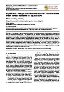
IV. SYSTEM ARCHITECTURE The Web Based Patient Monitoring Using ARM Processor system architecture has been developed to support the local sensing, signal processing, and autonomous decision support associated with local diagnostics, as well as the required ability for remote configuration and control. Figure1.System Architecture A. HARDWARE ARCHITECTURE B. AM1810 ARM Microprocessor The system architecture consists of three network tiers and is shown in Fig. 1. The system relies on the established Internet network infrastructure in the first tier, and then standard, ubiquitous wireless or GPRS or cellular data technologies (Wi-Fi or general packet radio service (GPRS)) in the second tier. The first two network tiers connect the personal server and the servers at hospitals or clinics. Raw sensor data or patient events and context can be transmitted to servers for storage or streamed to medical personnel for realtime monitoring of the patient condition. Based on the data received from one or more patients, new statistical models can be developed on the servers and sent back to the personal server for local signal processing along with other personalized patient information such as the patient‘s electronic medical record (EMR) via the GPRS or WiFi connection. In addition, medical personnel can send commands to the wearable system and configure the sensors used by the patient. The third network tier consists of a WLAN technology for the doctor‘s main pc. The system also consist of an electrocardiograph that detects and amplifies the heart electrical activity sensed through Electrodes attached to the skin surface in arms, legs and intercostal spaces. It is
20
The device is a Low-power processor that is specifically targeted for Profibus applications like industrial automation and medical applications. The device supports free operating system which can support all features, opulent user interfaces, and high processing performance. It has 32-bit RISC processor core and it performs 32-bit or 16-bit functions and processes 32-bit, 16-bit, or 8-bit data. It also has an 8KB RAM and 64KB ROM. It offers 10/100 Mb/s Ethernet MAC with Management Data Input/output module and four 64-bit generalpurpose timers which can be easily configurable. Furthermore a Management Data Input/output interface is offered. The SATA provides interface to mass data storage devices with high speed. The important feature of the ARM9 is it has Dual Gigabit Ethernet Ports with Integrated Switch and inbuilt Wi-Fi/Bluetooth Connectivity enhances the feature of our module. It also consists of Resistive touch LCD display which supports rotation and tilt capabilities via the on-board accelerometer.
Figure 2.ARM9 Architecture C.SOFTWARE ARCHITECTURE The software systems on the personal server, as shown in Fig. 3, are based on a client server architecture where a device server facilitates the connection between wireless sensing devices and client services. For our initial work, we have implemented clients for local signal processing, a GUI for patient interaction and data logging. These individual client programs are connected to each other and the device server via TCP/IP sockets, which enable reliable, language-independent communication across heterogeneous hardware in different locations. Through this network abstraction, other clients located on centralized servers can receive the patient data in real-time. More importantly, medical personnel may connect to patient‘s personal server and seamlessly monitor data in real-time or take control of the diagnostic processes on the personal server, if desired. Current security of the MEDIC system relies on traditional Secure Shell (SSH) protocol, whose keys are exchanged with the centralized server to allow secure connections.
(Hyper Text Markup Language) Working Group uses a free data base engine, SQLite which is a technology which forms database of local side in web browser and was not supported by any other web language. SQLite is not relatively good at mass works than general relation-type database but can store structural mass systemized relation-type data in a local flexibly if an engine is imbedded in web browser in small and medium scale and process data using standard query. In our project we are using database created using the Web SQL. W3C which are preparing HTML5 spec asserted they are going to extend local database with Indexed Database API, a new spec which is easier for standardization as an alternative while excluding Web SQL Database which has been marked a promising technology due to problems of Web SQL. But Web SQL is still receiving attention as there is any other formal web browser which supports Indexed DB[7]. We are creating web pages using HTML5. ‗Bio monitoring‘ which uses the most system resource are demanding the largest resource due the work of processing biological information with ‗Internet‘.it was found that certain amount was reduced in comparison with system resource consumption amount which arose in searching total DB and storing. The conventional system should connect to DB, search DB by query and stored in a system whenever there is any need of information.
A.WEBSQL DATABASE Figure3. Login page
Web SQL Database of HTML5 published byW3C (World Wide Web Consortium) HTML
21
online patients are given in figure 4. Zero indicates that the patient is offline status whereas one indicates the active mode, the physician can click on the patient who appears on line to view the patient‘s measurements as shown in Figure 5. Figure 5 shows the patient details such as name, age, address and IC, the current heart beat rate, heart beating history and temperature. Figure 6 shows the system Hardware module. VI. CONCLUSION The involvement of multiple factors in healthcare systems including diverse professionals and embedded devices has made web-based healthcare systems which uses internet technology. Internet technology makes it possible to interconnect independent devices and systems in an efficient and economical way. In order to develop dynamic, flexible, distributed and cost-effective applications, service-oriented computing, which relies on services, can be used. The key features of Web-based tools include timeliness in the dataflow (beyond national level) and the capability to handle complex health concerns which arise from a multiplicity of factors. Furthermore, since almost all clinicians have easy access to the Internet, the establishment of a Web-based registry and a Webbased reporting is usually feasible. Indeed, it represents an approach to enhancing the capacity to perform public health surveillance and, at the same time, it empowers users by providing them easy access to information that has been reviewed by work group members for accuracy and content. In particular, Safe Web-Registry, being a numerator count database, even if not a probability sample, can be considered a valuable tool for early warning problems with new products. This work provides the conceptualization for knowledge in emergency management and the representation of a device entity along with its attributes that can enable information and knowledge interoperability among other systems.
Figure4. Patient list
Figure5. Patient details
Figure6. Hardware module V. RESULTS
VII. FUTURE WORK
Figures from 3 to 5 show the sequence of the web pages according to the measurements process. Figure 3 requires the user name and password to access the system web site. Then after these pieces of information are typed in, the page for view the patient‘s ECG history and current
22
Our architecture, however, allows the usage of any other secure data transfer method, system with increasing patient data volume and system with fully wearable wireless sensor methods with automated diagnostics system with threshold based safety alarm methods which we plan to explore in our future work
VIII. REFERENCES [1] Khalid Elgazzar, Muhammad Aboelfotoh, Patrick Martin, Hossam S. Hassanein, Ubiquitous Health Monitoring Using Mobile Web Services, SciVerse ScienceDirect, Procedia Computer Science 10 ( 2012 ) 332 – 339 [2] Social Security Advisory Board, The unsustainable cost of health care, Sept. 2009, http://www.ssab.gov/documents/TheUnsustainableC ostofHealthCare graphics.pdf, [Accessed: Feb 25, 2012] [3] Health Research Institute, Healthcare unwired: New business models delivering care anywhere, Oct. 2010, http://www.lindsayresnick.com/Resource Links/Healthcare Unwired.pdf. [4] Anliker U, Beutel J, Dyer M, Enzler R, Lukowicz P, Thiele L,et al. A systematic approach to the design of distributed wearable systems. IEEE Trans Comput 2003;53:1017—33. [5] Seung-Man Chun, Jae-Wook Nah, Jong-Tae Park: Design and Implementation of IEEE 11073/HL7 Translation Gateway Based on UHealthcare Application Service for M2M, Journal of Korea Telecommunication Academy, 11-03 Vol. 36, No.3, 2011. [6] Young-Hyuk Kim, Il-Kown Lim, Jun-Woo Lee, Jae-Kwang Lee, ―Sensor Based Real-Time Remote Patient Monitoring System:A Study on Mobile DB Construction of Minimum Network Traffic in Use of HTML5 WebSQL‖, 1877-7058 © 2011 Published by Elsevier Ltd. [7] Winston H. Wu*, Alex A.T. Bui, Maxim A. Batalin,Lawrence K. Au, Jonathan D. Binney, William J. Kaiser MEDIC: Medical embedded device for individualized care, Artificial Intelligence in Medicine (2008) 42, 137—152 [8] Malcolm CLARKE: Developing a Standard for Personal Health Devices based on 11073, eHealth Beyond the Horizon-Get IT There, MIE 2008. [9] Lim, Chae Gyun, Lee, Ki Young, Lim, Myeong Jae, Jung, Yong Gyu, ―The Realities and Future of Medical Information Safety‖, Journal of Electronics Engineering Academy, Vo.37, No.6, 2010.
23
[10] Lee, Hyung Soo, ―WBAN Standard Trend and Analysis of Technology‖, TTA Journal, No.128, 2010. [11] S. Jassal, J. Brissenden, A. Raisbeck, J. Roscoe, Comparative cost-analysis of two different chronic care facilities for end-stage renal disease patients, Geriatric Nephrology and Urology 8 (1998) 69–76. [12] Lymberis A, Olsson S. Intelligent biomedical clothing for personal health and disease management: state of the art and future vision. Telemed J E-Health 2003;9:379—86. [13] Park S, Jayaraman S. Enhancing the quality of life through wearable technology. IEEE Eng Med Biol Mag 2003;22 : 41—8. [14] Lorincz K, Malan D, Fulford-Jones TRF, Nawoj A, Clavel A, Shnayder V, et al. Sensor networks for emergency response: challenges and opportunities. IEEE Pervasive Comput 2004 [15] Fulford-Jones TRF, Wei G-Y, Welsh M. A portable, low-power, wireless two-lead ekg system. In: Hudson DL, Liang ZP, Dumont G, editors. Proceedings of 26th International Conference of IEEE Engineering in Medicine and Biology Society. 2004. p. 2141—4. [16] P. Kulkarni, Y. Ozturk, mphasis: Mobile patient healthcare and sensor information system, Network and Computer Applications 34 (1) (2011) 402–417. [17] S. Dagtas, G. Pekhteryev, Z. Sahinoglu, H. C¸ am, N. Challa, Real-time and secure wireless health monitoring, International Journal of Telemedicine and Applications 2008 (2008) 1–10. [18] V. Oleshchuk, R. Fensli, Remote patient monitoring within a future 5G infrastructure, Wireless Personal Communications 57(2011) [19] S. Agarwal, C. T. Lau, Remote health monitoring using mobile phones and web services, Telemedicine and e-Health 16 (5) (2010) 603–607. [20] http://medical.nema.org/dicom.html
WIRELESS POWER TRANSFER SYSTEM SENTHIL NATHAN.M1 , PANDIARAJAN.K2 1 2
Student, III year Electronics & Communication,Karpagam College of Engineering,Coimbatore,India. Student, III year Electronics & Communication,Karpagam College of Engineering,Coimbatore,India.
[email protected] [email protected]
RF signal because of the dc pass filter.RL must be choosen such that the dc-converted portion of the RF power is maximized.
Abstract – In the present article wireless power transfer system has been reviewed.Microwave power transmission and inductive coupling methods are the most common methods for power transfer system.There are several type of rectenna for microwave power transfer.In this paper rectenna operation and its design are presented.Furthermore,theoratical analysis of RF to DC conversion efficiency of the rectifying diode used in rectenna are also been discussed.The method of inductive coupling and its design theory are presented in this article.The method used to increase the efficiency of the coil coupling and impedance matching methods are also been presented in this paper.
Fig.1.Block diagram of rectenna [13].
In the recent years,there has been a great development in the rectenna design.a circularly polarized rectifying antenna at 5.8GHz were developed with an RF to DC conversion efficiency of 80% for an input power level of 100mW [4].A new circularly polarized rectenna for wireless power transmission and data communication were developed which provides conversion efficiency of 57.3% for a load resistance of 300Ω [5].A high efficiency dual frequency rectenna at 2.45GHz and 5.8GHz were developed with an RF to DC conversion efficiency of 84.4% and 82.7% respectively [6].If rectenna operates at dual band it can be used for power transmission at either frequency depending upon power availability.In past rectenna developments,the single diode configuration is adopted in most rectifying circuits,which is acted as a half wave rectifier.to obtain double or even higher output a full wave rectifier can be applied.A circularly polarized dual-diode rectenna were developed with an RF to DC conversion efficiency of 76% at 5.8GHz [7]
I . INTRODUCTION Wireless power transmission (WPT) is the method of transmitting power from one place to another without the means of wires through atmosphere or vaccum.Nikola tesla conceived the idea of wireless power transmission and demonstrated the transmission of electrical energy through wires that depends upon electrical conductivity as early as 1891 [1].In 1893 tesla demonstrated the illumination of vaccum bulbs without using wires for power transmission at the world Columbian explosition in chicago [2].With the development of high power,high efficiency microwave tubes by Raytheon company , Waltham,Ma,in the 1950’s[3],the concept of NPT became a reality. The key technologies in the WPT system are discussed in this papper. Rectenna is the key component in the microwave power trwnsmission. The component of the rectenna are briefly discussed with the theoratical analysis of RF-to-DC conversion efficiency. The last topic of the paper discussed about the method of resonance inductive coupling for wire less transmission. The theory of coil coupling and the method to increase the coupling efficiency are also discussed briefly.
III . RECTENNA DESIGN The fig.1 shows the block diagram of the rectenna.the components of the rectenna are discussed below. A . ANTENNA
II . RECTENNA OPERATION THEORY
Circularly polarized antenna are now widely used because circular polarization avoids changing the output voltage due to the rotation of the transmitter or receiver.Various types of antennas are practically used.some of the antennas are horn antenna,patch antenna,microstrip antenna etc..The methods to increase the received power of an antenna system by combining polarization,space and frequency diversities were investigated in [8].As per the experimental results of [8] the increase in power is mainly contributed by the use of space diversity and the use of
Rectenna is the key component in microwave power transmission.A retenna is a rectifying antenna which is used to convert microwave energy into DC electricity. The high gain antenna couples the power into the circuit. A band-rejector filter located behind the antenna allows the incoming power to pass to the detector diode where a large portion of RF poert is converted to DC power. The remaining RF portion is bounted between the band reject filter and dc pass filter where it remix at the diode and forms more dc. The resistive load (RL) is isolated from any
24
circularly polarized element increased the received power by 2.6dB. The design of compact antenna for rectenna has been necessary to cope with the rapid growth of wireless applications.The techniques adopted to reduce the size of antenna were discussed in [9].And also the reconfigurable antennas are receiving much attention in RF energy harvesting models owing to their selectivity for operating ftrquency and polarization.Various antenna shapes and their reconfigurability were also discussed in [9].
Where the low frequency denominator asymptote is
(3) High frequency term is
B . LOW PASS FILTER The harmonic signals radiated by the rectifying circuits are a potential problem in rectenna design.the power level of the third harmonic may have the same as that of the second harmonic [10].Therefore microwave components such as an low pass filter must be added between the antenna and the diode to suppress these harmonics that improves the system performance and prevent harmonic interference.An efficient rectenna design with high harmonic rejection were described in [11,12].
(4) And ω is the angular frequency (2πf).RS is the diodes series resistance.Vbi is the forward bias turn on voltage of the diode and VD is the self-bias voltage due to rectification across the terminals of the diode.The variable θon refers to the forward bias turn-on angle of the diode [14].It is represented by
C . DETECTOR DIODE (5)
The diodes are used to convert RF to DC.The diode conversion efficiency (ƞD) is key in determining the rectenna performance.matching the diode’s input impedance to antenna impedance increases the efficiency.Three paramaters of diode such as breakdown voltage,zero-biased junction capacitance (Cjo) and series resistance (Rs) determine the power conversion efficiency of rectenna. Three parameters are related with each other due to the diode material properties [13].The diode efficiency is given by the following ratio (1)
By incorporating the friis transmission equation [15], equation (1) is rewritten as
(6) Pt and Gt represents the transmit power and gain of the transmitting array,Gr represents the gain of the rectenna,VD the voltage across the load resistor RL of the rectenna. λo represents the free space wavelength and Lpol represents the polarization mismatch for the circularly polarized rectenna and it is given by [15]. (7) In case of other types of polarized rectennas, Lpol can be neglected.The efficiency is normally expressed as a function of power density.The power density is given by [16]
(8) The commonly used diode is GaAs flip-chip schottky barrier diode (mode MA4E1317) from M/A com,Lowell MA. D . DC PASS FILTER Fig.2. Measured dc output voltages of the dual-diode and single-shunt diode rectennas [7].
The DC pass filter (capacitor) acts as a shorted stub matching network to not only tune out this diode reactance but also to optimize the remixing of the power at the harmonic frequencies.A broad band DC blocking chip capacitor is choosen as the DC pass filter.The capacitor is manufactured by dielectric laboratories Cazenovia,NY and
The RF to DC conversion efficiency as described in [4] is given by (2)
25
its series number is C08BLBB1X5UX. The capacitor is used to reflect all of the microwave energy arising from the diode from reaching the load resistor, thus returning the RF energy back to the diode.fig.4 and fig.5 shows the measured output voltages and the conversion efficiency respectively.
In [19] it has been assumed that the radiation loss is only in this circuit , the radiation resistance of each coil is given by the formula for an electrically short normal mode helical antenna.
Fig.5.Equivalent circuit model
The self & mutual Inductance of calculated by Neumann’s formula.
couples coils are
(9) Where ds1 and ds2 are the elements along each coil and r is the distance between ds1 and ds2 . A floating capacitance of each coil is given by approximating N turns coils as this conductor slices ,as
Fig.3. Measured and calculated conversion efficiencies of the dual-diode rectenna [7].
IV . INDUTIVE COUPLING One of the hottest issues in inductive coupling is non-radiative energy transfer.It is referred to as magnetic field resonance coupling .It is a combination of inductive coupling and resonance. Resonance improves the efficiency by tunneling magnetic field to a receiver coil which resonates at the same frequency.It was the first demonstrate by the group of MIT researchers in 2007[and they termed as witricity,standing for wireless electricity] and they were able to produce a power of about 60 Watts [17]. Later the researchers have demonstrated that the system’s efficiency in transmitting energy improves significantly when it is used to charge multiple devices at the same time and they were able to produce a power of about 100Watts [18].
(10) The coupling characteristics of two coils are calculated by these formulas.Coupled mode theory (CMT) [20] provides a simple and accurate way of modeling the system and gives a more understanding of what makes power transfer efficient in a coupled region. For CMT the needfull condition is that k