with arbitrary geometry. Numerical examples of the DOA estima- tion by a dipole array antenna, and an antenna array composed of a monopole antenna and a ...
1352
IEEE TRANSACTIONS ON ANTENNAS AND PROPAGATION, VOL. 53, NO. 4, APRIL 2005
Accurate DOA Estimation Using Array Antenna With Arbitrary Geometry Qiaowei Yuan, Qiang Chen, Member, IEEE, and Kunio Sawaya, Senior, Member IEEE
Abstract—The so called universal steering vector (USV) whose locus is equivalent to the array element pattern is applied to the direction of arrival (DOA) estimation by multiple signal classification (MUSIC) algorithm. It is shown that if the USV which includes the effect of the mutual coupling between the array elements is used, the compensation for the received voltage to remove the effect of the mutual coupling is not required any more. The USV for array antennas with arbitrary geometry is derived and evaluated efficiently by using the method of moments (MoM) so that the DOA estimation can be performed accuratly by using the array antenna with arbitrary geometry. Numerical examples of the DOA estimation by a dipole array antenna, and an antenna array composed of a monopole antenna and a planar inverted-F antenna (PIFA) mounted on a mobile handset are presented to demonstrate the effectiveness of the proposed method. Index Terms—Antenna array mutual coupling, antenna arrays, array signal processing, direction of arrival (DOA) estimation, method of moments (MoM), mobile antennas.
I. INTRODUCTION
I
T HAS BEEN pointed out that the accuracy of the direction of arrival (DOA) estimation using the multiple signal classification (MUSIC) algorithm is degraded due to the effect of the mutual coupling between the array elements. Therefore, many efforts have been made to remove the effect of the mutual coupling from the received voltage at the array terminals or from the steering vector, and then to apply the compensated received voltage or the compensated steering vector to evaluate the MUSIC spectrum [1]–[5]. The open-circuit voltage method has been proposed to compensate the effect of the mutual coupling by multiplying the received voltage vector by the impedance matrix of the array elements including the load impedance [6]. However, it has been pointed out that this compensation method is effective in the case of small dipole antenna but is not valid generally because the scattering effect of the antenna elements in the open-circuit state is ignored [2], [7], [8]. The mutual impedance has been redefined by taking the open-circuit scattering effect into account [2], [7], but the current distribution has to be estimated. The estimation becomes difficult when the structure of the array elements is complicated because the current distribution on each
Manuscript received April 19, 2004; revised October 30, 2004. This work was supported by the project of Creation of Innovative Clusters promoted by Ministry of Education, Culture, Sports, Science, and Technology of Japan. Q. Yuan is with Intelligent Cosmos Research Institute, Sendai 989-3204, Japan. Q. Chen and K. Sawaya are with the Department of Electrical Communications, Faculty of Engineering, Tohoku University, Sendai 980-8579, Japan. Digital Object Identifier 10.1109/TAP.2005.844409
antenna element depends on the direction and the polarization of the incident wave, as well as the geometry of the antenna elements. The compensation for the received voltage has been also carried out by the MoM [8], where the DOA of the incident waves is required. Generally speaking, it is difficult to compensate the received voltage to reconstruct the signal subspace because the compensation requires the information about the DOA of the incident wave in prior which is unavailable in DOA estimation. Approaches of using the actual array manifold defined as the array response have been suggested to find the DOA [9]. The array manifold is equivalent to the array element pattern in our opinion, and the method to obtain the array manifold is also called as the calibration method. In most cases, the actual array manifold is obtained by the measurement and requires huge storage to be saved in prior. Therefore, efforts have been made to get more exact array manifold with a less storage without considering the electromagnetic characteristics of the array antenna [9]–[12]. The method to obtain the array manifold from a fundamental electromagnetic perspective has also been proposed where the actual array manifold is calculated by the MoM to compensate the steering vector [5], and the problem of the cost of a large amount of storage is solved by using the distortion matrix with a limited size which is derived by comparing the actual array manifold (steering vector) with the ideal manifold in the limited number of directions, and the matrix is then approximately assumed to be independent of the DOA angle for saving the CPU time to calculate the matrix for every spatial spectrum. It has been found that the steering vector which is defined to be the array element pattern is affected greatly by the mutual coupling and the steering vector has been evaluated by using the EMF method [13], and analytical formulas [14] for some simple structures of the antenna arrays, but how to obtain the steering vector for general cases has not been clarified. In this paper, the so called universal steering vector (USV) whose locus is equivalent to the array element pattern is applied to the DOA estimation by means of MUSIC algorithm so that the received voltage at the terminals of array antennas can be used directly to calculated the MUSIC spectrum without compensation. An effective approach to calculate the USV without being saved at all searching directions is presented with the help of the full wave numerical analysis using the method of moments (MoM) for array antennas with arbitrary geometry. Also, the relationship between the USV and the conventional steering vector (CSV) is investigated. Finally, numerical examples of the DOA estimation by using a dipole array antenna, as well as an
0018-926X/$20.00 © 2005 IEEE
Authorized licensed use limited to: TOHOKU UNIVERSITY. Downloaded on August 10, 2009 at 01:59 from IEEE Xplore. Restrictions apply.
YUAN et al.: ACCURATE DOA ESTIMATION USING ARRAY ANTENNA
1353
array antenna composed of a monopole antenna and a planar inverted-F antenna (PIFA) mounted on a mobile handset are presented to demonstrate the effectiveness of the proposed method. II. DOA ESTIMATION BY MUSIC ALGORITHM WITH USV The received signal space of the array elements can be divided into two subspaces. One is the incident signal subspace spanned by the incident signal eigenvectors and the other is the noise subspace spanned by - noise eigenvectors. Both the signal eigenvectors and the noise eigenvectors can be calculated by the covariance matrix of the received voltage at the terminals of the antenna elements as (1) denotes the statistical expectation and superscript where denotes the complex conjugate transpose. Conventionally, the orthogonal property between the signal eigenvectors and the noise eigenvectors is utilized to estimate the DOA by searching the peaks of the MUSIC spectrum given by
(2) where and and are the searching angles, and the polarization of the incident wave is assumed to be known. is the matrix whose columns are the noise eigenvectors , and represents the CSV. of the covariance matrix Most of the previous researches have tried to convert the into the incident voltage vector received voltage vector , where does not include the mutual coupling effect only representing the voltage at each antenna and has size of is used to calculate in (1) element terminal. Then and the MUSIC spectrum in (2). However, the transformation into is possible only for special cases such from as the dipole array antenna where the compensation matrix is independent of the DOA. The compensation for mutual coupling effect usually requires the incident wave information such as the DOA and the polarization, but this information is practically not available. In this work, the USV defined by (9) is used to estimate the DOA without compensating the received voltage and the MUSIC spectrum is calculated by using the following:
(3) Since the USV can be evaluated for array antennas with arbitrary geometry as shown in Section III, the DOA estimation by means of the MUSIC algorithm can be used for any type of receiving array antennas including the effect of the mutual coupling between the array elements. It should be noted that the steering vector also depends on the polarization of the incident wave but the polarization of the incident wave is assumed to be known in this paper.
III. FORMULATION OF UNIVERSAL STEERING VECTOR A. CSV Assuming that an -element linear antenna array is used as the receiving antenna to estimate the DOA of incident waves from different directions. The received voltage vector with can be expressed by dimension of
(4) represents the ideal isolated element pattern where which is the same for all elements in array antenna having the denotes the electric field of th incisame elements. is the voltage vector with dident wave at the origin and caused by the white noise. is the CSV mension and the th element of is given with dimension by (5) is the where is the position vector of th array element, is reference location for the phase of the incident wave and the wave number vector of the th incident wave from direction . The CSV, which depends on the position of the array elements and the direction of the incident wave, does not include the mutual coupling between the array elements. B. USV The th element of the USV is denoted by which is the complex received voltage at the terminal of the th array and is element due to the incident wave from direction equivalent to the element pattern of the th array element. Although the USV can be obtained by the measurement of the actual complex array element pattern of each element directly, the accurate measurement of the array element pattern is not easy [15] and requires the huge storage to save the measured data. An efficient method to evaluate the USV by using method of moments (MoM) is presented in the following. The array antenna with arbitrary geometry is shown in Fig. 1 as an example of the receiving array for the DOA estimation. In the MoM analysis, the th element of the array is divided segments and the total number of the segments of the into . depends on the segment size and array is for wire antenna structure. The segment size less than structure in Richmond’s MoM procedure is necessary to obtain a satisfactory accuracy. Then, the matrix equation for unknown currents on all segments is obtained as (6) is the current vector with dimension of reprewhere is the senting the unkown currents on all segments. impedance matrix whose element represents the mutual impedance between th and th segments. The impedance mais independent of the incident wave which is evaluated trix
Authorized licensed use limited to: TOHOKU UNIVERSITY. Downloaded on August 10, 2009 at 01:59 from IEEE Xplore. Restrictions apply.
1354
IEEE TRANSACTIONS ON ANTENNAS AND PROPAGATION, VOL. 53, NO. 4, APRIL 2005
Fig. 1. Array antenna with arbitrary geometry for DOA estimation.
numerically by using the full wave electromagnetic analysis. is the voltage vector representing the inner product of the weighting functions and the incident electric field for all segments. The Richmond’s method from direction where the piece-wise sinusoidal is used as basis and weighting functions is employed in this work, the detail for evaluations is given in [17], and the evaluation of of th of element is simple analytic form which is omitted here. Once vector and matrix are evaluated, the unknown current vector can be obtained by (7) where is the inverse matrix of , i.e., the admittance matrix. Since the currents at the terminal segments of the antenna element are part of , they can be extracted from (7) and expressed as
and a multiplication of requires evaluation of matrix by vector, whose computational cost is not too large to be calculated. C. Relationship Between USV and CSV It is noted that the CSV is equal to the incident voltages at the terminal segments of array antenna and is the part of . If each array element is not divided, i.e., the , the CSV is equal to . However, in order to calculate the mutual coupling accurately by using MoM, the array antenna is usually divided into segments to meet the requirement that the dipole segment . The relationship between size should be less than the CSV and can be expressed as the follows: (10) where
(8) is the current vector with dimension of reprewhere senting the currents at the terminal segments and with diis the part of corresponding to the mutual mension of admittances between the segments on the terminals and all the includes segments of the array elements. It is clear that the effect of the mutual coupling not only from the terminal segments, i.e., the feed points, but also from all the segments of the antennas. Assuming that the terminal of the array element is loaded by an impedance of , the USV which represents the received voltage taking account of the effect of the mutual coupling between the array elements is given by (9) Authough the in (9) has to be evaluated for every in the spatial spectrum, since is searching angle and can be calculated and stored before no relation with in (9) only the DOA estimation, the calculation of
represents the CSV with dimension of , and is the transformation matrix with dimension of . Obviously, depends on the searching direction . Substituting (10) into (9), the following expression can be obtained: (11)
and the USV can be expressed by (12) where
defined by (13)
is the matrix and plays a role to compensate the CSV in (10) and in (12) are used just for in (12). explaining the relationship between the USV and the CSV as shown in (12), but not for evaluating the USV from the CSV in in (12) is the same practice. Although the purpose of to the impedance matrix in the open-circuit voltage method [6] to compensate the mutual coupling either for restoring the
Authorized licensed use limited to: TOHOKU UNIVERSITY. Downloaded on August 10, 2009 at 01:59 from IEEE Xplore. Restrictions apply.
YUAN et al.: ACCURATE DOA ESTIMATION USING ARRAY ANTENNA
Fig. 2.
1355
Six-element dipole array.
Fig. 3. MUSIC spectrum by using six-element dipole array with array spacing of 0:5�.
Fig. 4. MUSIC spectrum by using six-element dipole array with array spacing of 0:1�.
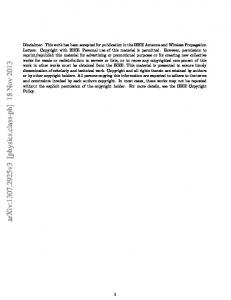
steering vector or for restoring received signals, there is an and the impedance matrix. essential different between depends on each searching angle and polarization, while the impedance matrix does not. It is the difference that makes the USV compensate the CVS perfectly and estimate DOA in MUSIC algorithm accurately. Using the CSV for DOA estimation requires that all the element should be the same, while if the USV is used, the receiving array antenna with arbitrary geometry and arbitrary element spacing is acceptable. IV. SIMULATION RESULTS A. Dipole Array Fig. 2 shows a six-element linear dipole array antenna for the numerical simulation. The length of dipole element is and each dipole antenna is loaded by 50 resistance. Four incident waves with polarization are assumed and the DOA , and , , , and , of each wave is respectively. The SNR of all the waves is 20 dB. The MUISC spectrum obtained by the CSV, the USV and Dandekar’s method [5] are compared in Figs. 3 and 4 when array spacing is and , respectively. These figures show that the DOA is accurately evaluated by using the USV and Dandekar’s method for both cases. On the other hand, the MUISC spectrum of the in the case of CVS cannot distinguish the DOA of and cannot estimate any DOA in the case of . B. Monopole-PIFA Array for Mobile Handset Fig. 5 shows another model of array antenna for the simulation composed of a monopole antenna and a planar inverted-F antenna (PIFA) antenna. The combination of such antennas has been used in the mobile handset to achieve the diversity reception. The radiation pattern of each antenna element is different
Fig. 5.
Monopole-PIFA array mounted on mobile handset.
from each other and much affected by the ground plane and the mutual coupling between the elements [16]. Therefore, the DOA cannot be evaluated correctly unless the effect of ground plane and the mutual coupling is exactly included into the DOA estiand – mation. The MUSIC spectrum for is evaluated for two cases. Fig. 6 shows the result of case 1 where the incident wave with vertical polarization from the direcand is assumed, while Fig. 7 shows tion of the result of case 2 where the incident wave with horizontal pofrom the direction of and is larization assumed. The input SNR for both cases is 20 dB. The MUISC spectrum obtained by the CSV, the USV and Dandekar’s method are compared in Fig. 6 for case 1. This figure shows that the DOA is correctly evaluated by using the USV but the method
Authorized licensed use limited to: TOHOKU UNIVERSITY. Downloaded on August 10, 2009 at 01:59 from IEEE Xplore. Restrictions apply.
1356
IEEE TRANSACTIONS ON ANTENNAS AND PROPAGATION, VOL. 53, NO. 4, APRIL 2005
mutual coupling matrix, a dynamic matrix depending on the searching direction and polarization. Theoretically the matrix could include the mechanical and electrical errors due to the mutual coupling between the array elements. The numerical examples have been shown when a dipole array antenna and an array antenna composed of a monopole antenna and a planar inverted-F antenna (PIFA) mounted on a mobile handset are used as the receiving antenna, demonstrating the high accuracy of the present method.
ACKNOWLEDGMENT Fig. 6. MUSIC spectrum obtained by using monopole-PIFA array. (Case 1: E polarization).
The authors would like to thank Prof. T. Maeda of Ritsumeikan University, Kyoto, Japan, for his helpful advice.
REFERENCES
Fig. 7. MUSIC spectrum obtained by using monopole-PIFA array. (Case 2: E polarization).
using the CVS and Dandekar’s method are invalid in this case. It indicates that the distortion matrix in [5] is effective in compensating the array antenna such as the dipole array, but cannot compensate the coupling effect in the present case where the distortion matrix strongly depends on the incident direction. Fig. 7 shows that the present method is effective where the DOA has polarization. These numerical results indicate that the the effect of the ground plane and the mutual coupling can be dealt with correctly by the present method.
V. CONCLUSION The USV whose locus is equivalent to the array element pattern has been applied to the DOA estimation by means of MUSIC algorithm so that the received voltage at the terminals of the array antenna can be used directly to calculate the MUSIC spectrum. An effective approach to calculate the USV has been shown by using the method of moment for the array antenna with arbitrary geometry. The relationship between the USV and the CSV has been shown indicating that the USV can be regarded as the CSV compensated by the inverse of the
[1] K. M. Pasala and E. M. Friel, “Mutual coupling effects and their reduction in wideband direction of arrival estimation,” IEEE Trans. Aerosp. Electron. Syst., vol. 30, pp. 1116–1122, Apr. 1994. [2] H. T. Hui, “Improved compensation for the mutual coupling effect in a dipole array for direction finding,” IEEE Trans. Antennas Propag., vol. AP, no. 9, pp. 2498–2503, Sep. 2003. [3] H. Yamada, R. Hara, Y. Ogawa, and Y. Yamaguti, “On performance of calibration techniques for mutual coupling effect in array antennas,” Proc. IEICE, vol. AP2002-218, pp. 179–186, Mar. 2002. [4] C. H. Yeh, M. L. Leou, and D. R. Ucci, “Bearing estimation with mutual coupling present,” IEEE Trans. Antennas Propag., vol. 37, no. 10, pp. 1332–1335, Oct. 1989. [5] K. R. Dandekar, H. Ling, and G. Xu, “Experimental study of mutual coupling compensation in smart antenna applications,” IEEE Trans. Wireless Commun., vol. 1, no. 3, pp. 480–487, Jul. 2002. [6] I. J. Gupta and A. A. Ksienski, “Effect of mutual coupling on the performance of adaptive arrays,” IEEE Trans. Antennas Propag., vol. AP-31, pp. 785–791, Sep. 1983. [7] H. T. Hui, “Reducing the mutual coupling effect in adaptive nulling using a re-defined mutual impedance,” IEEE Microw. Compon. lett., vol. 12, pp. 178–180, May 2002. [8] R. S. Adve and T. K. Sarkar, “Compensation for the effects of mutual coupling on direct data domain adaptive algorithms,” IEEE Trans. Antennas Propag., vol. 48, no. 1, pp. 86–94, Jan. 2000. [9] R. O. Schmidt, “Multilinear array manifold interpolation,” IEEE Trans. Signal Processing, vol. 40, pp. 857–866, Apr. 1992. [10] A. J. Weiss and B. Friedlander, “Manifold interpolation for diversely polarized arrays,” Proc. Inst. Elect. Eng. Radar, Sonar and Navig., vol. 141, no. 1, pp. 19–24, Feb. 1994. [11] A. Manikas, R. Karimi, and I. Dacos, “Study of the detection and resolution capabilities of one-dimensional array of sensors by using diffential geometry,” Proc. Inst. Elect. Eng. Radar, Sonar and Navig., vol. 141, no. 2, pp. 83–92, Apr. 1994. [12] B. Friedlander and A. J. Weiss, “Direction finding in the presence of mutual coupling,” IEEE Trans. Antennas Propag., vol. 39, no. 3, pp. 273–284, Mar. 1991. [13] A. Kato and Y. Kuwahara, “Steering vector taking mutual coupling effects into consideration,” in Proc. IEEE AP-S Symp., 2000, pp. 914–917. [14] Y. Kuwahara, “Steering vector of MSPA array taking mutual coupling effects into consideration,” in Proc. ISAP, 2000, pp. 1614–1617. [15] Y. Inoue, K. Mori, and H. Arai, “DOA estimation in consideration of the array elemnt pattern,” in Proc. IEEE 55th VTC, vol. 2, May 6–9, 2002, pp. 745–748. [16] Q. Yuan, Q. Chen, and K. Sawaya, “Radiation characteristics of array antennas for mobile handsets,” in Proc. 6th Int. Symp. Antennas, Propagation and EM Theory (ISAPE’03), Oct. 2003, pp. 352–355. [17] J. H. Richmond and N. H. Greay, “Mutual impedance of nonplanar skew sinusoidal dipoles,” IEEE Trans. Antennas Propag., vol. AP-23, no. 3, pp. 412–414, May 1975.
Authorized licensed use limited to: TOHOKU UNIVERSITY. Downloaded on August 10, 2009 at 01:59 from IEEE Xplore. Restrictions apply.
YUAN et al.: ACCURATE DOA ESTIMATION USING ARRAY ANTENNA
Qiaowei Yuan received the B.E., M.E., and Ph.D. degrees from Xidian University, Xi’an, China, in 1986, 1989, and 1997, respectively. From 1990 to 1991, she was a Special Research Student at Tohoku University, Sendai, Japan. From 1992 to 1995, she was a Researcher in Sendai Research and Development Laboratories, Matsushita Communication Company, Ltd., and from 1997 to 2002, a Researcher in Sendai Research and Development Center, Oi Electric Company, Ltd. She is currently with Intelligent Cosmos Research Institute, Sendai, Japan, involved in the research and development of antennas and RF circuits for mobile communications.
1357
Kunio Sawaya (M’77–SM’02) received the B.E., M.E., and D.E. degrees from Tohoku University, Sendai, Japan, in 1971, 1973, and 1976, respectively. He is presently a Professor in the Department of Electrical and Communication Engineering at Tohoku University. His areas of interests are antennas in plasma, antennas for mobile communications, theory of scattering and diffraction, antennas for plasma heating, and array antennas. Dr. Sawaya is a Member of the Institute of Image Information and Television Engineers of Japan. He received the Young Scientists Award in 1981 and the Paper Award in 1988 both from the Institute of Electronics, Information and Communication Engineers (IEICE) of Japan. He is now the Chairman of Technical Group of Antennas and Propagation of the IEICE from 2001 to 2003.
Qiang Chen (M’97) received the B.E. degree from Xidian University, Xi’an, China, in 1986 and the M.E. and D.E. degrees from Tohoku University, Sendai, Japan, in 1991 and 1994, respectively. He is currently an Associate Professor with the Department of Electrical Communications, Tohoku University. His primary research interests include computational electromagnetics, adaptive array antennas, and antenna measurement. Dr. Chen is a Member of the Institute of Electronics, Information and Communication Engineers (IEICE) of Japan, and the Institute of Television Engineers of Japan. He received the Young Scientists Award in 1993 from the IEICE. He has served as the Secretary and Treasurer of IEEE Antennas and Propagation Society Japan Chapter in 1998. He is currently the Secretary of Technical Committee on Electromagnetic Compatibility of IEICE.
Authorized licensed use limited to: TOHOKU UNIVERSITY. Downloaded on August 10, 2009 at 01:59 from IEEE Xplore. Restrictions apply.