Keywords: adaptive equalization, data recovery, DFE, link. Introduction ... can be temporarily put out of service without disrupting the flow of data, and calibrated ... backplane: FR4 material, 9" and 26" trace length, top and bottom routing layers.
Adaptive Equalization and Data Recovery in a Dual-Mode (PAM2/4) Serial Link Transceiver Vladimir Stojanović1,2, Andrew Ho1, Bruno Garlepp1, Fred Chen1, Jason Wei1, Elad Alon1,2, Carl Werner1, Jared Zerbe1, and Mark A. Horowitz2 1
2
Rambus, Inc., Los Altos, CA 94022, USA Department of Electrical Engineering, Stanford University, CA 94305, USA Abstract
To achieve high bit rates link designers are using more sophisticated communication techniques, often turning to 4PAM transmission or decision-feedback equalization (DFE). Interestingly, with only minor modification the same hardware needed to implement a 4PAM system can be used to implement a loop-unrolled single-tap DFE receiver. To get the maximum performance from either technique, the link has to be tuned to match the specific channel it is driving. Adaptive equalization using data based update filtering allows continuous updates while minimizing the required sampler front-end hardware and significantly reduces the cost of implementation in multi-level signaling schemes. A transceiver chip was designed and fabricated in a 0.13µm CMOS process to investigate dual-mode operation and the modifications of the standard adaptive algorithms necessary to operate in high-speed link environments. Keywords: adaptive equalization, data recovery, DFE, link Introduction
Attenuation [dB]
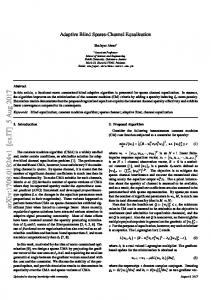
High-speed link rates are entering the region where the bandwidth of the wires in cables or backplanes becomes severely limited by dielectric loss, skin-effect and impedance discontinuities. Additionally, in many applications the wires within a system can have significantly different channel characteristics, as shown in Fig. 1. In these systems, achieving optimal performance for each link requires a flexible equalization/modulation solution that can adapt to the specific requirements of its channel [1]. By re-using the circuits in the 4PAM receiver, we were able to seamlessly incorporate a 2PAM receiver with one tap of feedback equalization using loop unrolling [2], without additional cost. Slight changes in the 4PAM clock and data recovery scheme efficiently track signals with a controllable inter-symbol interference (ISI) component, required in 2PAM receiver operation with one tap of loop unrolling. While many systems use one time calibration at link 0 -10
startup, this paper explores a more robust approach which allows the links to be continually adapted to track changes in the channel or the transceiver chips. We extend the previous work on multi-level equalizing transceivers [1,3] by using insight into standard adaptive algorithms to create a modified version that significantly decreases the overhead circuits needed to monitor the link performance and guide the adaptation of the link. Adaptive High-Speed Link System Design In order to explore techniques for automatic link configuration with minimal hardware overhead, we built an adaptive link, extending the design in [1]. The link, shown in Fig. 2, has both transmit pre-emphasis and feedback equalization and can operate in both 2PAM and 4PAM modes, to efficiently combat ISI over various backplane channels. This relatively complicated signal processing system has many parameters that need to be tuned for optimal performance (e.g. equalization coefficients, receiver offsets and thresholds, choice of 2PAM or 4PAM). To enable system independent communication of transmit pre-emphasis updates, a common-mode backchannel is included as part of the link transceiver cell [4]. In addition to the standard data slicers and edge samplers to facilitate 2x oversampled clock and data recovery, the receiver has one extra sampler (the adaptive sampler in Fig. 2) used for monitoring the link performance [5]. This adaptive sampler has variable timing and voltage references and in addition to monitoring performance during link operation it also provides the information necessary for the adaptive equalization and link configuration algorithms. Since the magnitude of the received signal is significantly attenuated due to channel rolloff and limited swing at the transmitter, a significant part of the design is dedicated to the calibration of the receive samplers, to make the effective input referred offset as small as possible. We used a multiplexing method where each of the edge or data samplers can be temporarily put out of service without disrupting the flow of data, and calibrated offline. During the calibration dLev
9" FR4
Tx Data
-20 -30
error aClk
26" FR4
-40
Rx data
9" FR4, via stub
-50
Channel
2
4
6
Adaptive macro
dClk
thresholds
26" FR4, via stub
-60 0
adaptive sampler
8 10 frequency [GHz]
Fig. 1 Frequency response of different channels within the same backplane: FR4 material, 9" and 26" trace length, top and bottom routing layers.
tap updates
edge
CDR
eClk
aClk dClk eClk tap updates
Fig. 2 Adaptive multi-level equalizing link architecture.
1 + αD
1
1+ α
+1
1+ α
1−α
1−α
+α
−α −1+ α
−1
d n | d n −1 = 1
+α
0
xn
d n | d n −1 = 1
−1 − α
−α
−1−α
d n | d n −1 = 0
DQ
dClk
−1+α
d n −1
d n | d n −1 = 0
dClk
(a) (b) Fig. 3 One tap DFE using loop-unrolling: a) Transmitted 2PAM signal levels corrupted by ISI split to ±1±α levels at the receiver and can be recovered with two slicers offset by the amount of ISI ±α b) Practical implementation of the one tap DFE using loop-unrolling.
Instead of just one data sampler for 2PAM signaling, the receiver now has two samplers that are offset by ±α, anticipating the impact of the trailing ISI tap α, from a previously sent symbol of value of ±1. While this presents significant overhead in a simple 2PAM receiver, as shown in Fig. 4, we re-use the inactive samplers of the 4PAM link (when in 2PAM mode) to implement such a scheme with no front-end hardware overhead. Given that in such a signaling scheme the first tap of trailing ISI is not really physically cancelled in the channel but rather predicted by the receiver (based on previously prDFE enable
thresh (+)
D Q
0
D Q
1
dClk
x
D Q
D Q
1 1 D Q
dClk
0
D Q
lsb(+)
D Q
D Q
prDFE enable
D Q
0 1
D Q
Link Equalization We use sign-sign LMS (a derivative of the well-known least-mean square (LMS) algorithm [7]) to adapt our equalization taps since it is one of the simplest adaptive algorithms. It creates updates for the tap coefficients (w) based only on the sign of the data and the measured error (1) wnk+1 = wnk + ∆w sign(d n−k )sign(en ) where n is the time instant, k is the tap index, dn is the received data and en is the error of the received signal with respect to the desired data level, dLev. A. Dual-Loop Adaptive Equalization One issue in using sign-sign LMS for transmit preemphasis based equalization, which is often used in high-speed links, is that the ideal reference level dLev, from which the error signal is created, is unknown a priori. This problem arises because the peak output swing constraint in the transmitter forces the equalizer to attenuate the lowfrequency components of the signal to match the loss of the signal at high frequencies, Fig. 5a. Thus, the amount of voltage swing available at the receiver depends on the frequency characteristics of the channel. One of the solutions to alleviate this effect, proposed in our earlier work [8], was to introduce a variable gain element at the receiver (prior to slicer input), which was adjusted during adaptation such that constant reference levels are maintained in the data slicer. A more practical and power efficient approach for high-speed links is to adaptively adjust the reference level of the data slicer, rather than amplifying the signal. Thus we create a second loop which adjusts dLev to track the signal level using the following updates (2) dLevn +1 = dLevn − ∆dLev sign(en ) . At each iteration, the adaptive sampler is adjusted using (2) to provide the error signal en for both the signal level (2) and equalizer tap (1) loops. The peak-to-peak error and dLev setting are shown in Fig. 5b, for initial and final iteration of the algorithm. In order to obtain the highest signal levels at the receiver, maintain transmit output peak constraint, and avoid the trivial stability point of both loops (at zero tap magnitudes and signal level), the proposed values of the equalization taps errorinitp-p dLevinit
0
unequalized
-5
errorendp-p
-10
prDFE enable 0
dClk
thresh (-)
0
received data), we are faced with two issues with respect to automatic link configuration. First, it is necessary to modify the adaptive algorithm for transmit pre-emphasis to tolerate one tap of trailing ISI, and second, the magnitude of this trailing ISI needs to be estimated such that data slicing and clock recovery can be robustly performed.
Attenuation [dB]
period, the adaptive sampler takes the role of the sampler under calibration. Each sampler has a 5-bit dedicated offset canceling digital-to-analog converter (DAC), and a shared 8-bit DAC for threshold selection, while the adaptive sampler has a 9-bit DAC for adaptive twist, dLev, setting. The muxing method enables both swapping of the outputs of each of the samplers with the adaptive sampler and independent swapping of the adaptive twist DAC with the threshold DAC for a particular sampler. This calibration removes both the sampler offset and any residual threshold DAC errors. To increase the performance of the link in 2PAM mode, we added one tap of immediate feedback equalization in the receiver, without increasing its complexity. As shown by Kasturia [2] and more recently by Sohn [6], one tap of feedback equalization can be achieved by using loop unrolling to avoid the bottleneck in the latency of the feedback loop. Since we cannot run the feedback loop fast enough, we unroll it once and make two decisions each cycle. One comparator decides the input as if the previous output was a 1, and the other comparator decides the input as if the previous bit was a 0. Once we know the previous bit, we select the correct comparator output, as shown in Fig. 3.
msb
-15
dLevend
…
equalized
-20 -25 0
lsb(-)
Fig. 4 Integration of 2PAM partial response DFE receiver with loop unrolling into 4PAM receiver by re-use of 4PAM lsb slicers. Loop unrolling path is shaded.
frequency [GHz] 0.5
1
1.5
2
2.5
Initial eye
Equalized
(a) (b) Fig. 5 Effect of peak voltage swing constraint on transmit pre-emphasis: a) frequency view b) Scaling of the dLev reference loop (2) in a dual-loop interaction with the equalizer loop. As the signal gets more equalized, scaling in the transmitter decreases the value of received signal and reference loop adjusts dLev accordingly.
after every iteration (1) need to be rescaled such that the sum of their magnitudes always equals the maximum allowed by the peak swing constraint. A simple, implementation driven approximation of this rescaling modifies the update algorithm such that the update on the main tap is computed from the updates of the other taps and the peak constraint requirements, rather than using its own update information. Rather than having 4 error samplers, one for each possible level, as proposed by Stonick et al [3], we use only one adaptive sampler and perform updates only when data is received that corresponds to the signal level at which the adaptive sampler is located. We trade-off the convergence time for receiver simplicity since convergence is not a problem with multi-Gb/s data rates and slow channel changes. B. Decision-Feedback Equalization using Loop Unrolling Similarly, the dual-loop adaptive framework can be extended directly to support feedback equalization using loop unrolling. Instead of the filtering the error signal and loop updates (for both dLev and equalizer taps) by the bit values that form the current received symbol, we can apply data filtering with the current and past bit in order to lock the dLev to one of the four signal levels (±1±α), present in a one tap DFE system. This filter is very similar to data filtering for 4PAM equalization. A similar algorithm, but without data based update filtering, was proposed for one tap DFE by Winters and Kasturia [9] and incurs significant sampler overhead. Using just one adaptive sampler and data based update filtering we estimate the size of the trailing ISI in an iterative manner. In the first phase, loop updates are filtered by the (dn,dn-1)=(1,1) criterion to lock dLev to the 1+α level, and in the second phase, updates are filtered by (dn,dn-1)=(0,1) to lock to the 1-α level. During these two phases, the equalizer only compensates for the error caused by ISI taps other than the first trailing tap, as shown in Fig. 6. Equalization and locking phases one and two are interleaved such that the optimal value of trailing ISI is found at the point when all other ISI has been minimized by the
transmit equalizer and long-latency feedback equalizer (reflection canceller [1]). This is necessary since the absolute magnitude of the main and trailing ISI tap change due to rescaling which maintains the peak power constraint in the transmitter. Clock and Data Recovery for Loop Unrolling We have already seen in Fig. 6 that the presence of the trailing tap of ISI causes the received signal to have four levels, similar to 4PAM albeit non-uniformly separated. The transitions from one level to another are guided by the values of the future, current and immediately preceding data bits, as shown in Fig. 7. This forms two distinct modes or principal zero crossings, denoted by arrows in Fig. 7. In order to avoid this bi-modal behavior, we could filter out one type of transition by filtering the edge crossings in the clock and data recovery (CDR) block. This is done in a way similar to that in 4PAM clock and data recovery, where edge-filtering is used to eliminate the edges that cause tri-modal zero crossing distributions [1]. Using this approach we can directly extend the 4PAM CDR filtering based on two bit symbols, to partial response CDR filtering based on pairs of current and preceding bits. (0,1)
(1,0)
(1,0)
(1,1) (0,1)
(1,0) (0,0)
Fig. 7 Bi-modal transitions in 1+αD channel: first mode (1,1)→(1,0) and (0,0)→(0,1), second mode (0,1)→(1,0) and (1,0)→(0,1).
Since edge filtering decreases the probability of CDR updates and puts additional constraints on first-order CDR loops in plesiochronous systems, additional samplers can be used to make use of minor transitions in 4PAM systems [1]. In the partial response mode of operation, we make use of these lsb edge samplers, offsetting them by the amount of trailing ISI and align the edge slicing timing as shown by the left arrow and three dotted levels in Fig. 7. In this way, no transitions are lost and the rate of CDR updates is maximized. Clock and data recovery front-end remains the same as in 4PAM case (three edge samplers providing tentative early/late information), while the transition filtering section either uses lsbn(+), msbn and lsbn(-) data in 4PAM mode, or msbn and msbn—1 in 2PAM partial response mode, as shown in Fig. 8. thresh (+)
D Q
0
Fig. 6 Joint equalization and extraction of the trailing tap magnitude. Plots are based on simulation using the measured pulse response, Fig. 9, obtained with the adaptive sampler; symbol time is 200ps. a) Locking of dLev to (1,1) level – eye as seen by the upper sampler in Fig. 3b, b) Locking to (0,1) level – eye as seen by the lower sampler in Fig. 3b, c) Final locking point of dLev to (1,1) level after equalization, d) Final locking point of dLev to (0,1) level after equalization. Sampler thresholds are offset by the extracted final magnitude of the trailing ISI 0.5*(dLev(1,1)-dLev(0,1)) (dashed line).
(0,1)
eClk
x
D Q
edgen (+) lsb n(+) edgen (0)
4PAM msb n, msb n-1
eClk
D Q
thresh (-) eClk
edgen (-)
2PAM prDFE
lsb n(-) filtered early/late
Fig. 8 Generation of early/late updates in 2x oversampling CDR loop, in 4PAM and 2PAM with partial response DFE modes.
Experimental Results Using adaptive sampler we can scan out the pulse response of the whole channel as seen by the receiver, including any bandwidth limitations in the receiver. Figure 9 illustrates the pulse responses before and after equalization. The pulse response equalized for one tap DFE at 5Gb/s, 26” FR4 channel, is about 60mV (40%) larger than the fully equalized pulse, due to peak output power constraint in the transmitter. 0.4
0.25
[V] unequalized
0.3
[V]
transmit equalized with one tap DFE
0.2
fully transmit equalized
0.15
0.2
0.1
0.1
0.05 0
0
[ps] 0
(a)
1000
2000
3000
4000 (b) 0
1000
2000
3000
[ps] 4000
Fig. 9 E-scope, [5], of the pulse response: a) unequalized, b) transmit equalized with one tap DFE and fully transmit equalized. Dots indicate symbol spaced sample points (symbol time is 200ps).
100 dLev learning curve (a) dLev speed 1x, eq speed 1x (b) dLev speed 10x, eq speed 1x (c) dLev speed 1x, eq speed 10x
code [lsb]
(b)
60 40
(a)
(c)
20 0 0
20
40
60
equalizer tap learning curves (a)
100 50 0 -50 0 100 50 0 -50 0 100 50 0 -50 0
code [lsb]
code [lsb]
80
code [lsb]
One of the important issues in the dual-loop adaptive algorithm is the balance of the update rates for the equalizer and reference level loops. Our measurements show that the equalization algorithm is stable for a relatively wide range of update speeds of one loop with respect to another, Fig. 10.
80 100 # updates
20
40
60
80
100 (b)
20
40
60
80
100 (c)
20
40
60
80 100 # updates
Fig. 10 Dual-loop adaptive learning curves for different speeds of the dLev and equalizer tap loops, 2PAM at 5Gb/s over 20” FR4. Updates are filtered on received data being high (since adaptive sampler tracks the positive signal level) and then block averaged by 127 to smooth the sign-sign gradient estimate.
-2 -3
150
log10(BER)
-5
[mV]
0
-9
-50
-10
-100 0
20
40
60 80 margin [mV]
-4
50
-7 transmit equalized -8 with one tap DFE
-11
-3.5
100
-6
(a)
-3
200
fully transmit equalized
-4
100
(b)
log10(voltage probability distribution)
The steep slope of the BER vs. noise margin curves, Fig. 11a, suggests that random noise components (jitter and voltage thermal noise) are relatively small and that ISI is the most dominant error term.
-4.5 -5 0
50
100
150
200 [ps]
Fig. 11 a) Comparison of bit error rate (BER) vs. receiver noise margin for fully transmit equalized link and transmit equalized with one tap DFE, b) Statistical shmoo of the eye diagram as presented to the positive lsb sampler for one tap DFE.
It is interesting to observe the shape of the equalized eye in a loop unrolling DFE scheme, Fig. 11b. While not as symmetric as a fully equalized 2PAM eye, it is actually slightly more robust to jitter. Measured peak-to-peak jitter
from the 2.5GHz recovered clock shows that CDR dither decreases from 14ps to 5ps when one tap DFE is used instead of full transmit pre-emphasis. This tri-modal edge distribution is partially avoided in the one-tap DFE scheme since the first post tap of the transmit pre-emphasis is not significantly engaged. Inherent PLL jitter was 26ps peak-to-peak. Conclusion It is possible to integrate a 2PAM one-tap DFE into a 4PAM receiver with minimal additional hardware by leveraging the multi-level aspects of the partial response signals in loop-unrolled DFE. Clock and data recovery techniques for these partial response signals are derived from standard multi-level edge filtering schemes. Adaptive equalization can also be added to a transceiver for a small hardware cost. The key is to first modify the popular sign-sign LMS procedure to enable adaptation under peak voltage swing constraint in the transmitter and then to incorporate data filtering methods. The data filtering enables adaptation using a single monitoring sampler even in multi-level schemes like 4PAM and loop-unrolled 2PAM DFE. Taken together these techniques enable a single, hardware efficient link cell design to operate autonomously at 5-10Gb/s over a variety of channels. Acknowledgments The authors would like to acknowledge the help and support of the whole Rambus RaserX design team. V. Stojanovic and M. A. Horowitz would like to acknowledge the support of MARCO Interconnect Focus Center. V. Stojanović, A. Ho and E. Alon would like to thank I. Stojanović, M. Ho and M. Lee for their whole hearted support. References [1] J. Zerbe et al, "Equalization and Clock Recovery for a 2.5-10Gb/s 2-PAM/4-PAM Backplane Transceiver Cell," IEEE International Solid-State Circuits Conference, Feb. 2003, San Francisco. [2] S. Kasturia and J.H. Winters, "Techniques for high-speed implementation of nonlinear cancellation," IEEE J. Selected Areas in Communications, vol. 9, no. 5, Jun 1991, pp. 711-717. [3] J.T. Stonick et al, "An adaptive pam-4 5-Gb/s backplane transceiver in 0.25-µm CMOS," IEEE J. Solid-State Circuits, vol. 38, no. 3, March 2003, pp. 436-443. [4] A. Ho et. al, “Common-mode Backchannel Signaling System For Differential High-Speed Links,” to be published. [5] J. L. Zerbe et al, “1.6Gb/s/pin 4-PAM signaling and circuits for a multidrop bus,” IEEE J. Solid-State Circuits, vol. 35, May 2001, pp. 752-760 [6] Y-S. Sohn et al, “A 2.2Gbps CMOS look-ahead DFE receiver for multidrop channel with pin-to-pin time skew compensation,” IEEE Custom Integrated Circuits Conference, September 2003 [7] B. Widrow et al,, “Stationary and nonstationary learning characteristics of the LMS adaptive filter,” Proc. IEEE, vol. 64, no. 8, pp. 1151-1162, 1976. [8] V. Stojanović, G. Ginis and M.A. Horowitz, "Transmit Preemphasis for High-Speed Time-Division-Multiplexed Serial Link Transceiver," IEEE International Conference on Communications, pp. 1934 -1939, May 2002. [9] J.H. Winters and S. Kasturia, “Adaptive nonlinear cancellation for high-speed fiber-optic systems,” IEEE J. of Lightwave Technology, vol 10, no. 7, July 1992, pp. 971-977.