for off-line low-cost power supplies which require input/output isolation. Since the voltage on the primary switch at the turn-on instant is high and the associated ...
Adaptive Off–Time Control For Variable-Frequency, Soft-Switched Flyback Converter At Light Loads Yuri Panov and Milan M. Jovanovic Delta Products Corporation Power Electronics Laboratory 5101 Davis Drive Research Triangle Park, NC 27709 Abstract - The soft switching of a flyback converter can be achieved by operating the circuit in the critical conduction mode. However, the critical-mode operation at light loads cannot be maintained due to a very high switching frequency and the loss of the output voltage regulation. A control which regulates the output down to the zero load and maintains soft switching at light loads is proposed. The proposed control scheme was implemented in the 380 V/19 V, 65 W flyback dc/dc converter.
I. INTRODUCTION Due to the minimum number of semiconductor and magnetic components, a flyback converter is a very attractive candidate for off-line low-cost power supplies which require input/output isolation. Since the voltage on the primary switch at the turn-on instant is high and the associated capacitive turn-on loss is substantial, the switch soft turn-on is highly desirable. The soft switching is also helpful in reducing the size and loss of the EMI filter. The soft turn-on of the primary switch is accomplished in the flyback converter operating in the critical conduction mode, i.e. at the boundary of Continuous and Discontinuous Conduction Modes (CCM/DCM). The critical mode of operation requires a Variable Frequency (VF) control to regulate the output voltage against input-voltage and load variations. Operation of the VF flyback converter in the critical mode is discussed in [1]-[4]. However, the VF critical-mode control suffers from a wide frequency range and loss of the output voltage regulation at light load. Namely, for this control, the switch on-time should decrease, as the load current decreases. However, since the minimum on-time of the controller is limited by its internal delays, the converter operating in the critical mode cannot maintain the output regulation at light load. This problem can be alleviated by limiting the minimum controller off-time to a fixed value, so that converter switches from the critical operation mode at high load to the DCM with constant off-time at light load, as implemented in [4], [5]. However, it was found experimentally that the constant off-time control could not maintain the output regulation as the load current approaches zero value. The control implementations in [4], [5] also do not provide soft switching at light load. The objective of the paper is to propose a simple VF converter control which maintains the output regulation and soft switching in the entire load range.
II. CONVENTIONAL OFF-TIME CONTROL OF VF FLYBACK CONVERTER AT LIGHT LOAD A. Principle Of Operation The functional diagram of the VF flyback converter with constant off-time control at light load and its waveforms are shown in Fig. 1. The zero crossing of the secondary current is sensed by the CCM/DCM detector, which monitors voltage VSENSE across sensing winding NSENSE. After secondary current iSEC reaches zero, the magnetizing inductance of the transformer starts resonating with the parasitic capacitances of the primary switch and secondary rectifier. As a result, voltage VSENSE also resonates, as shown in Fig. 1b. When voltage VSENSE goes negative, detector output signal B becomes high. The error amplifier EA provides the reference signal VEA, which is compared with the sensed switch current iSW⋅RS. When the switch current reaches the VEA/RS value, the RS latch, which controls the gate drive, is reset. The way the latch is set depends on the load. At heavy load (Fig. 1b), secondary current fall time TFALL is longer than the duration of the output pulse V of the Monostable Multivibrator (MMV). When the secondary current goes below zero, detector output signal B changes from “0” to “1”, propagates through gate G1, and after delay TD sets the latch. Delay TD between the secondary current zero-crossing and primary switch turn-on provides the switch turn-on with the voltage VIN − N ⋅ VO across it. As a result, the switching loss is substantially reduced. At light load (Fig. 1c), the secondary current fall time is shorter than the MMV output pulse duration. The output signal of CCM/DCM detector cannot propagate through gate G1 until the MMV output pulse expires. Therefore, at light load, the switch off-time is determined by the MMV output pulse duration. B. Limitations The analysis in this Section facilitates the explanation of limitations of the constant off-time control at light load. All converter components were assumed ideal for analysis purposes. The analysis was performed for the 380 V/19 V, 65 W flyback converter. The full-load switching frequency of the converter was selected to be 35 kHz which is above the audible range. The corresponding transformer primary-side magnetizing inductance was LM = 1.27 mH. To keep the switch voltage stress below 600 V, the transformer has turns ratio N = 5:1.
i sw LM VIN
VGS
POWER STAGE
N = Np/Ns
isec Ns
Np
TON
TOFF
+
D
TS
Vo -
CF
+
TFALL
+
SW
VDS -
+
VGS -
VEA /RS
i sw
N SENSE
CCM/DCM Detector
+
VSENSE - B
-
Comp. B
+
VIN
Z2
Comp. A
Z1
+
R
NVo NVo
VDS
VSENSE
Rs
A
isec
VEA
-
Q
E/A
-
B,D
+
TD
Vref
S RS Latch Reset Dominant
E
D
Delay TD
V G1
V
provide light-load operation
TOFF (MIN)
E
MMV
(a)
The peak value IPEAK of switch current ISW is related to the on-time TON and fall time of the secondary current TFALL as: V ⋅T I PEAK = IN ON , (1) LM VO ⋅ TFALL ⋅N , (2) LM Load current is equal to the average value of the secondary ⋅T I (3) current: I O = PEAK FALL ⋅ N . 2 ⋅ TS From (1) and (2), the relationship between the on-time and (4) TON TFALL = M ⋅ N , fall time is: where M = VO VIN is the voltage conversion ratio. From (2) and (3), one can derive: V ⋅ ( N ⋅ TFALL )2 IO = O . (5) 2 ⋅ LM ⋅ TS In the critical mode, TS = TON + TFALL . (6) Combination of (4), (5) and (6) produces expressions: I 2 ⋅ LM ⋅( 1 + M ⋅ N ) , TFALL = O ⋅ (7) VO N 2
(b)
VGS
TON
TOFF
VEA /RS
i sw
I PEAK =
I 2 ⋅ LM ⋅ ( 1 + M ⋅ N )2 . TS = O ⋅ (8) 2 VO N It follows from the last expression that in the critical mode the switching frequency is inversely proportional to the load current. Theoretically, the switching frequency approaches infinity when the load current approaches zero. This implies
isec
TFALL
VDS
NVo NVo
VIN
B
V TOFF(MIN)
D
E
TD
(c) Fig. 1. Conventional control of VF flyback converter: (a) functional diagram; (b) heavy-load waveforms; (c) light-load waveforms.
that in the critical mode the converter would suffer from an extremely wide frequency range and excessive switching losses at light load.
Another limitation of the critical mode operation at light load comes from the fact that, practically, the minimum on-time of the controller is limited to 0.5-0.9 us by the delays of the comparator and logic circuitry of the controller IC. If the required on-time becomes smaller than the control IC minimum on-time, the controller can no longer maintain the output regulation. Reduction of the controller minimum on-time time is possible by refining the IC circuitry, but it causes a sensitive increase of the IC cost. From (4) and (7), the minimum output power value POmin crit at which the controller is able to regulate the output in the critical mode is equal: min ⋅ VIN ⋅ VO ⋅ N TON = (9). POmin crit LM ⋅ ( 1 + M ⋅ N ) min For TON =0.8 µs, POmin crit value computed from (9) is 8.6 W.
The switching frequency which corresponds to POmin crit is close to 250 kHz. For lower loads, the output-voltage regulation of the VF converter in the critical mode cannot be maintained. The output regulation at the loads below POmin crit can be achieved by operating the converter in DCM with the constant min . For the constant off-time control, off-time TOFF min TS = TON + TOFF , and expressions (4), (5) are employed to derive the minimum output power at which the controller is still able to regulate the output with constant off-time: 2
min VIN ⋅ TON . min min + TOFF 2 ⋅ LM ⋅ ( TON ) 2
POmin dcm =
(10)
Minimum Power (W) 300 100 30
Critical Mode
10
DCM
3
0.7 W
1 0.3
2
5
10 20 Minimum Off-Time (us)
50
100
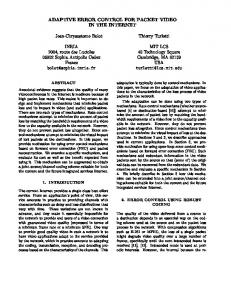
Fig. 2. Calculated minimum load attainable in critical conduction mode and in DCM for conventional off-time control.
To facilitate explanation of the constant off-time control limitation, the minimum output power attainable in the critical mode and in DCM is graphed in Fig. 2 as a function of the minimum off-time. The minimum output power attainable with the constant off-time control was computed based on (10), and the minimum output power attainable with the critical-mode control was computed based on (4) and (9). If the converter is
expected to operate down to 0.7 W load, then, based on Fig. 2, the minimum off-time should be chosen to be 51 µs. However, min for TOFF =51 µs, the critical-mode operation starts only at the load above 100 W. This means that the 65-W converter will min value operate in DCM in the entire load range. As the TOFF increases, the output regulation range increases, but at the same time the load level at which converter shifts from the critical mode to DCM increases. The trade-off between the output regulation at light load and critical mode of operation at high load cannot be satisfied for the conventional off-time control. Also, as can be seen from Fig. 1c, the conventional control loses soft switching at light loads.
III. PROPOSED OFF-TIME CONTROL OF VF FLYBACK CONVERTER AT LIGHT LOAD A. Principle Of Operation The functional diagram of the proposed control is shown in Fig. 3a. Heavy-load waveforms of the proposed control coincide with those of the conventional control. Its key waveforms at light load are shown in Fig. 3b. To solve the problem of the output regulation at light load, the proposed control adaptively increases the off-time as the load decreases. To implement the adaptive control, the MMV pulse duration is adjusted in accordance with the erroramplifier output signal VEA which indirectly carries information about the load. The MMV implementation is shown in Fig. 4. The duration of the MMV output pulse V is adjusted by varying the comparator threshold as a function of the error-amplifier output signal VEA. In Fig. 4a, capacitor C is charged through the parallel combination of resistors R1 and R2 during the on-time, and is discharged through resistor R1 during the off-time. Time constant τ 1 = R1 ⋅ C is selected to be comparable with the maximum TOFF value, while time constant τ 2 = ( R1|| R2) ⋅ C should guarantee the charge of the capacitor to the Zener diode min . Zener diode ZD assures breakdown voltage VZD during TON charging of capacitor C to the same level independently of the magnitude of the gate-drive signal. The relationship between the off-time and the signal VEA on the inverting input of the MMV comparator is: min VEA = VZD ⋅ exp( TOFF / τ1 ). (11) At the switch turn-off instant, VEA = I PEAK ⋅ RS . (12) Solution of the equations (1), (9), (11), and (12) produces the dependence of the off-time upon the output power in DCM which is plotted in Fig. 5. Fig. 5 also contains a plot of the ontime versus the load. The computed curves consist of two different pieces. For the load above 1.5 W, the on-time stays min above its minimum value TON , and both TON and TOFF change in response to the load variation.
i sw
isec Ns
LM Np
VIN
R2
+
+
VDS -
VGS -
D
Vo -
CF
NSENSE +
VSENSE -
VGS
TON
+
D
+
SW
VGS
POWER STAGE
N = Np/Ns
ZD
TOFF
R1
C
CCM/DCM Detector
V
+ + Vc - VEA
Vc
VEA V
(a)
-
VZD
(b)
+
B
Fig. 4. Implementation of Monostable Multivibrator with a variable pulse width: (a) functional diagram; (b) key waveforms.
Comp. B
Z1 Rs
R
Z2
Comp. A
Q
+
S RS Latch
A
VEA
-
Time (us) 100
-
EA
TOFF
+
(DCM)
Vref
E
R
Delay TD
MMV
D
C
V
"1"
D
Q
C
provide light-load operation
G1
D Flip-Flop
TON
0.1 0.2
VGS
(DCM)
0.5
1
2 5 10 20 Output Power (W)
50
100
TON
VEA /RS
i sw
Fig. 5. Calculated on-time and off-time for the proposed control.
For the load below 1.5 W, the on-time has reached its minimum value, and only the off-time varies with load change. The relationship between the off-time in the critical mode and the load current is also plotted in Fig. 5. The intersection of the TOFF curves corresponding to the critical mode and DCM shows the point where the converter changes its mode of operation. The change of the operation mode occurs at the 38 W load level.
isec VDS
B
V
TOFF(MIN) C
D
E
TOFF (Critical Mode)
1
(a)
TOFF
10
TD
(b) Fig. 3. Proposed VF Flyback Converter Control: (a) functional diagram; (b) light-load waveforms.
B. Soft Switching At Light Load To retain soft switching at light load, the proposed control turns on the switch when voltage VDS reaches the resonance valley. As shown in Fig. 3a, the voltage VDS minimum is detected by sensing the instant when voltage VSENSE changes its polarity from positive to negative, and, then, delaying the turnon instant for a quarter of the resonant period. To turn-on the switch in the resonance valley, the D flip-flop is added to the controller circuitry. After MMV output pulse V has expired, the D flip-flop waits for voltage VB to cross the zero level in the negative direction. As soon as this event happens, the D flipflop changes its output state from “0” to “1”, and after delay TD turns on the switch. With delay TD taken into account, the primary switch turn-on occurs exactly in the resonance valley of its drain-source voltage waveform.
C. Design Considerations The control circuitry determines the output power POmin crit at
fs (kHz) 60
which the converter shifts from the critical mode of operation to DCM. The POmin crit level is usually selected based on considera-
50
tions of the circuit efficiency and frequency range. As the POmin crit
40
value decreases, the operating frequency range increases. The desirable POmin crit value can be achieved by proper selection of
30
Zener diode breakdown voltage VZD and time constant τ 1 = R1 ⋅ C of capacitor C in Fig. 4. The calculated relationship between POmin crit , maximum operating frequency and design parameter T = (LM /VIN)⋅(VZD /RS) for different τ1 values is plotted in Fig. 6. As voltage VZD increases, the POmin crit level increases, and the maximum switching frequency decreases. The value of τ1 is limited by several factors. A lower τ1 value can result in a nearly zero voltage across capacitor C at the end of the off-time, causing the MMV comparator to become more susceptible to noise. A higher τ1 value can result in an undesirably high POmin crit level, as can be seen from Fig. 6. These considerations determine the design range for the constant τ1. min
Po crit (W)
fs max (kHz)
60
15 us
90
10 us
50 1
40
= 5 us 80 70
min
Po crit
fs max
30 20
10 us 15 us
10 0
60
5 us
50 40
20
40 60 80 Design Parameter T (us)
100
Fig. 6. Calculated dependence of minimum critical-mode load power and maximum switching frequency on control design parameters.
The calculated dependence of the switching frequency upon load is plotted in Fig. 7 for selected design parameters. In the 38-65 W load range, the converter operates in the critical mode, and the switching frequency increases from 35 to 58 kHz as the output power decreases. In the 1.5-38 W range, the converter operates in DCM with variable on and off times. The frequency starts decreasing and drops to 35 kHz at the 1.5 W load. At this power level, the on-time reaches its minimum value (0.8 µs). If the load is reduced below 1.5 W, the converter operates with the constant on-time, and the off-time grows rapidly as the load decreases. At the minimum load (0.7 W), the frequency drops to 19 kHz. Thus, the proposed control provides the converter operation in the entire load range with the frequency variation from 19 to 58 kHz.
T = 13 us 1 = 10 us
20 10 0.5
1
2
5 10 20 Output Power (W)
50
100
Fig. 7. Calculated switching frequency versus load for proposed control.
IV. HARDWARE EVALUATION OF PROPOSED CONTROL Experimental waveforms of the 380 V/19 V, 65 W flyback converter with proposed control for heavy, light, and very light loads are shown in Fig. 8. At full load (Fig. 8a), the duration of the MMV output pulse V is shorter than the secondary-current fall time. At the instant when the secondary current falls to zero, the output signal B of the CCM/DCM detector in Fig. 3a propagates through gate G1 and after delay TD turns on the switch. As a result, the converter operates in the critical mode. As the load decreases from 65 W to 10 W, the duration of the MMV output pulse increases from 9.5 to 11.6 µs, and it becomes longer than the fall time of the secondary current (Fig. 8b). The CCM/DCM detector output signal cannot turn-on the switch until the MMV output pulse expires. As a result, the converter operates in DCM. As can be seen from Figs. 8a and 8b, the switch turns on in the resonance valley with the minimum voltage across it both at heavy and light loads. At very light load (Fig. 8c), the duration of the MMV output pulse increases to 24.3 µs. The resonance decays significantly during the off-time, and the voltage on the switch at the turn-on instant is close to VIN. The measured switching frequency is plotted versus load in Fig. 9. For comparison, Fig. 9 also shows the calculated switching frequency curve. The converter operates in the critical mode in the 35-65 W load range. For loads below 35 W, the converter operates in DCM. When the load decreases below 23 W, the on-time reaches its minimum value requiring the controller to increase the off-time significantly. For this reason, the switching frequency drops down for a load below 2-3 W. This frequency drop is an additional benefit of the proposed control since it reduces the switching loss at very light load.
fs (kHz)
VGS (20 V/div)
80
VDS (200 V/div)
60
iSEC (5 A/div)
calculated
70
50
measured
40 30 20
V
10
0
10
20
30 40 50 Output Power (W)
60
70
(a)
VGS (20 V/div) VDS (200 V/div)
iSEC (2 A/div) V
(b)
VGS (20 V/div) VDS (200 V/div)
iSEC (2 A/div) V
(c) Fig. 8. Experimental waveforms of VF flyback converter with Schottky rectifier: (a) Po = 70 W; (b) Po = 10 W; (c) Po = 0.4 W.
Fig. 9. Measured switching frequency of experimental prototype vs. load.
The shape of the frequency curves in Fig. 9 is related to the internal structure of MC34262 IC which was used in the control circuitry. This IC is intended for PFC applications and has an internal multiplier whose input/output characteristic is responsible for the curves’ appearance. V. SUMMARY It was demonstrated that the constant off-time control of the VF flyback converter cannot regulate the output as the load current approaches a zero value. A simple adaptive control was proposed which regulates the output down to zero load. The proposed control also maintains the soft-switching at light loads. An additional advantage of the adaptive control is the switching frequency reduction at light loads. The proposed control was successfully implemented in the 380 V/19 V, 65 W flyback converter. REFERENCES [1] P. Greenland, S. Sandler, "Consumer-Oriented Quasi-Resonant Flyback Converter Suits Broader Applications", Power Conversion And Intelligent Motion Magazine, April 1988, pp. 9-19. [2] J. B. Lio, M. S. Lin, D. Y. Chen, W. S. Feng, "Single-Switch, SoftSwitching Flyback Converter", IEE Electronic Letters, June 1996. [3] "TDA 4605-3 Control IC for Switched-Mode Power Supplies Using MOSTransistor", Siemens Data Sheet and Application Note. [4] Critical Conduction GreenLine SMPS Controller, Motorola Analog IC Device Data. Rev. 1, Document MC33364/D. [5] UC3852 High Power Factor Preregulator, Unitrode Product and Applications Handbook 1995-96, pp. 6-278 - 6-282.