First, there are image-space algorithms that render something (such as a ...
extract lines by doing some sort of image processing on the framebuffer. (for
simple ...
Part IV: Algorithms for Finding Lines Szymon Szymon Rusinkiewicz Rusinkiewicz Line Line Drawings Drawings from from 3D 3D Models Models SIGGRAPH SIGGRAPH 2005 2005 Course Course Notes Notes
1
Classes of Algorithms Image-space: – Render some scalar field, perform signal processing (thresholding, edge detection, etc.)
– Sometimes can use hardware to achieve same effect
Object-space: – Extract lines directly on surface
Hybrid: – Mostly graphics hardware tricks [Isenberg 2003]
There are two major classes of algorithms for extracting most kinds of lines from 3D meshes. First, there are image-space algorithms that render something (such as a depth map or cosine-shaded model), then extract lines by doing some sort of image processing on the framebuffer (for simple operations such as thresholding, there are often ways of achieving the same effect using texture mapping, or vertex or pixel shaders). The advantage of this kind of algorithm is that it can be fast, easy to implement, and provides some notion of view-dependent level of detail. A major disadvantage is that it makes it difficult to control the appearance and stylization of the resulting lines. A second class of algorithm operates in object space – on the model directly. These algorithms tend to be a little more complex, and it is more difficult to adapt them to take advantage of graphics hardware. On the other hand, they provide good control over stylization. Finally, there are hybrid (usually multi-pass) algorithms, which perform a bit of processing in object space, but the lines ultimately show up only in the frame buffer. These are much less general than the other kinds of algorithms, and are specialized for e.g. contours. 2
Contours: Image-Space Algorithm Recall: occluding contours = zeros of n · v Simple algorithm: render n · v as color, threshold – Variant: index into texture based on n · v – More variants: environment map, pixel shader
Let’s start with occluding contours (or interior and exterior silhouettes), and look at image-space algorithms. A very simple technique is to render a lit version of the model (without color), then perform a thresholding step: any region darker than a threshold is set to black (or the line color), and anything above the threshold is set to the background color. There are many ways to do this thresholding step as part of the rendering, using pixel shaders, texture mapping, environment mapping, etc.
3
Line Thickness Drawback: line thickness varies – Thicker lines in low-curvature regions
One major problem with this algorithm is that the thickness of the lines can vary, sometimes quite a bit. There are a few tricks to get around this problem.
4
Line Thickness Control Solution #1: mipmap trick – Load same-width line into each mipmap level
Original
New
First, you can use a texture map indexed by n dot v, but use mipmapping. The trick is to make the width of the black region in the texture map the same width in all mipmap levels.
5
Line Thickness Control Solution #2: curvature-dependent threshold – Test n ⋅ v < ε κ r
Original
New
Another solution is to take advantage of the fact that, for a constant-curvature region, you can determine how thick the lines will be as a function of radial curvature. Then, the approximation is to change the threshold depending on the square root of radial curvature.
6
Contours: 2nd Image-Space Algorithm Render depth image, find edges – Simpler rendering: no normals – More complex image processing: edge detector vs. thresholding
There’s a second, completely different, image-space algorithm that’s possible. Now, instead of rendering n dot v, we render a color that depends on depth (or just look at the depth buffer instead of the color buffer). The image processing operation we have to do here is more complicated: edge detection instead of just thresholding. This is an interesting tradeoff: we have made the rendering simpler, but the image processing more complex.
7
Contours: Object-Space Algorithm Main advantage over image-based algorithms: can explicitly stylize lines Algorithm depends on definition used: edges between front/back-facing triangles vs. zeros of interpolated n · v For first definition: loop over all edges – Test adjacent faces – If one frontfacing, one backfacing, draw edge – Can be done in hardware [McGuire 2004]
Let’s now move to object-space algorithms for contour extraction. Recall that we talked about two possible definitions of contours on polygonal meshes: contours along the mesh edges (separating frontfacing and back-facing faces), or contours within faces (zeros of interpolated n dot v). For the first definition, a simple brute-force algorithm is just to loop over all edges, and check whether each has one adjacent frontface and one adjacent backface.
8
Contours: Object-Space Algorithm Advantage: no problems with visibility Disadvantage: can get self-intersecting paths – Makes stylization difficult Frontfacing Backfacing Contour
This has the disadvantage that the contour, when viewed as a path along mesh edges, can form loops.
9
Contours: Object-Space Algorithm [Hertzmann 2000] Alternative: zeros of “Phong”-interpolated n · v For each vertex: compute n · v For each face: if signs at three corners not same, interpolate to find zero crossing within face n·v > 0 n·v = 0
n·v < 0
n·v < 0
The other definition involves computing n dot v at each vertex, then looping through all faces of the mesh. For each face, you first ask whether n dot v has a different sign at some vertex. If so, you interpolate along edges connecting positive-(n dot v) vertices and negative-(n dot v) vertices to find zeros, then connect the two points with a segment.
10
Cubic Interpolation Better: use value and derivative at vertices
Linear interpolation
Cubic interpolation
The usual way of doing this interpolation is linear, though if you compute derivatives of n dot v, you can also do a more accurate higher-order Hermite interpolation. (For reference, the derivative of n dot v at a vertex in the direction of an edge is sin(theta) * w^T * II * e, where theta is the arc-cosine of n dot v, II is the second fundamental matrix, and w and e are the projections of the normalized view and edge directions into the same tangent-plane coordinate system in which II is expressed.)
11
Acceleration Techniques Goal: avoid touching all vertices, faces, or edges
Normal cone bounding hierarchy [Sander 2000] – Tree with nodes containing cone of normals of children
– Leaf node for each face – Traverse tree checking view direction against cone
Both of these object-space algorithms are brute-force: they require looping over all the edges, vertices, and/or faces of the model. There is a large body of work on acceleration techniques that try to reduce running time. For the contours-within-faces case, one popular technique is to construct a hierarchical data structure, where each node stores a bounding cone of the normals below it. At run time, the tree is traversed, and any nodes for which the cone is entirely frontfacing or entirely backfacing can be pruned.
12
Acceleration Techniques Gauss map [Gooch 1999] – Discretize space of normals – For each edge, find path between normals of faces • Store pointer to edge in normal “bucket”
– At run time, check edges corresponding to circle of normals
Preprocess
Normals perpendicular to view
Runtime
Another interesting acceleration technique involves the Gauss map. As a preprocess, a data structure is built that represents the space of possible directions (the space of directions conceptually corresponds to a sphere, but usually a cubemap is easiest to work with). For each edge, we compute an arc (shown in yellow) between the directions corresponding to the normals of the two faces touching that edge. Each direction intersected by this arc gets a pointer back to the edge. At run time, we check all directions corresponding to the normals perpendicular to the view: any arc that intersects that circle of directions (shown in green) represents an edge that is part of the silhouette (in practice, a superset of edges is generated because of the discretization of the Gauss map, so candidate edges must be verified).
13
Acceleration Techniques Randomized seed-and-traverse [Markosian 1997] – Pick random faces – If found contour, walk along it to extract whole loop – Also use contour faces from previous frame as seeds – Not guaranteed to find all contours, but likely to have found all big ones after a few frames
A very different sort of acceleration technique, most suited to interactive systems, relies on randomization. We pick random faces on the mesh, and check whether they contain a contour. If so, we follow the contour by walking to adjacent faces, eventually extracting an entire contour loop. In order to improve the efficiency of the random testing, we can test those faces that contained a contour in the previous frame before resorting to the random testing. This algorithm, of course, is not guaranteed to find all the contours unless we test all faces. However, it is very likely that all significant contours will be found, and the reliance on temporal continuity means that it is very likely that after a few frames it will find everything.
14
Visibility Any object-space algorithm must handle visibility – Local occlusions: “inside” contours (have κr < 0) – Non-local occlusions
Visible contours “Inside” contours Occluded
Regardless of the details, all object-space contour finding algorithms must deal with the problem of visibility. Although we’ll look at some strategies for this later on, for now let us emphasize the fact that there are two ways in which a contour can be invisible: it can be occluded by a distant portion of the mesh, or it can be occluded locally. The latter pieces of the contour can be identified simply by checking the sign of the radial curvature, so at least part of the visibility problem can be solved locally. Full visibility is usually resolved using an algorithm such as ray tracing or zbuffering.
15
Hybird Algorithm for Finding Contours Two-pass algorithm [Raskar 1999] – Draw frontfaces in white, offset towards viewer – Draw enlarged backfaces – Can be done in one pass with modern hardware [Raskar 2001]
– Does not need a mesh: works for point/surfel clouds [Xu 2004]
Let’s look at one algorithm in the “hybrid” category. Imagine doing a standard rendering pass, then keep the z-buffer on and render just the backfaces slightly enlarged (which can be done by actually changing the geometry, or by rendering the backfaces using thick outlines). Around the contours, the second rendering pass will “peek out” from behind the geometry rendered on the first pass. This is a nice algorithm because it can be very fast (modern graphics hardware can do it in one pass), and requires neither additional data structures nor image processing. However, just as with image-space algorithms, there is no control over stylization.
16
Algorithms for Suggestive Contours Definition 1: search over viewpoints Definition 2: find local minima Definition 3: extract zero crossings
[DeCarlo 2003, 2004]
Let’s move on to algorithms for suggestive contours. There are three different definition, and each gives rise to a different algorithm. The first definition, “contours in nearby views”, is difficult to work with and requires a search over viewpoints.
17
Possible Algorithms Definition 1: search over viewpoints Definition 2: find local minima Definition 3: extract zero crossings Render diffusediffuse-shaded image
Filter image to detect valleys in intensity
The second definition, “local minima of n dot v”, gives rise to an image-space algorithm in which an (n dot v)-shaded image is rendered, and a “valley detection” filter is used to detect valleys of intensity.
18
Possible Algorithms Definition 1: search over viewpoints Definition 2: find local minima Definition 3: extract zero crossings
Finally, the third definition, “zeros of radial curvature (subject to a derivative test)” naturally leads to an object-space algorithm.
19
Suggestive Contours as Zeros of κr
Mesh
κr = 0
This algorithm extracts loops where radial curvature is zero, using either a brute-force approach or one of the acceleration techniques we talked about…
20
Suggestive Contours as Zeros of κr
κr = 0
Reject if Dwκr < 0
Then, the derivative (in the projection of the view direction, which we’ve been calling w) of the radial curvature is tested at each point along the curve, and we reject regions where it’s negative.
21
Suggestive Contours as Zeros of κr
Reject if Dwκr < 0
Suggestive contours
Finally, we can stylize the lines however we want, such as this style that fades out strokes as the derivative of curvature approaches zero.
22
Stability Some curves unstable – under perturbations to geometry (e.g., due to noise)
– under changes in viewpoint
Observation: not drawn by artists Solution: prune these curves away
This algorithm can be augmented to throw out some of the unstable lines.
23
Unstable Suggestive Contours
The idea is that if, at an inflection corresponding to a zero of radial curvature, the curvature is varying rapidly, that location is stable.
24
Unstable Suggestive Contours
On the other hand, these shallow inflections are rather unstable…
25
Unstable Suggestive Contours
The addition of the slightest bit of noise causes perturbations in the suggestive contours, and might introduce new ones (or delete existing ones). So, one way to prune strokes is to apply some threshold to the magnitude of the curvature derivative, which eliminates these shallow inflections.
26
Pruning Based on Speed Definition of stability: lines that move slowly when view changes Suggestive contours remain stationary when camera moves within normal plane
[DeCarlo 2004]
A more principled way of pruning suggestive contours is to calculate how fast they move with respect to changes in viewer position: lines that move quickly are unstable and should be pruned.
27
Speed of Suggestive Contours Consider motion perpendicular to curve (along ∇κr) Derive speed using implicit function theorem κr ∂κ r max |vsc | =
∂κ r ∂c
∂c
∇κ r
0
p
p’ slope = |∇ |∇κr|
We can derive this speed from the implicit function theorem, which says that we have to look at both how quickly radial curvature is changing with respect to camera motion (numerator), and how quickly radial curvature is varying over the surface (denominator).
28
Speed of Suggestive Contours
Projected speed w.r.t. angular camera motion =
2 cosθ − K sin θ ∇κ r
Conclusion: unstable suggestive contours when – looking straight at a surface – shallow inflection
Stable suggestive contours when – approaching contours – approaching K = 0 lines [DeCarlo 2004]
Working out the math, we get this formula. Looking at the individual terms, we can see that velocity will be largest, hence the curves most unstable, when the terms in the denominator are zero. These correspond to sin(theta)=0 (looking at the surface) and gradient(kr)=0 (shallow inflections). Conversely, when the terms in the numerator are zero we have the maximal stability. This happens when cos(theta) is near zero (i.e., approaching a true contour), or when the Gaussian curvature is small (approaching the parabolic lines). This is a mathematical explanation of why suggestive contours (when considered over all views) tend to hug the parabolic lines.
29
Results of Pruning
View 1
View 2 Pruning based on (sin2θ ) Dwκr / |w|
Pruning based on s.c. speed
Here are a couple of examples of pruning according to the formula for the speed (right), or according to a simpler formula that just tries to avoid shallow inflections and lines seen head-on (center).
30
Non-Exhaustive Extraction Extending methods originally used for contours Hierarchical Algorithm [Gooch 99] – Sphere/cone hierarchy – In initial experiments, pruning not as effective as for contours
Stochastic Algorithm [Markosian 97] – Test a subset of faces for zero crossing – Once found, follow loop – Result: find most lines using 1-10% of faces as seeds
Very similar acceleration techniques to those used for contours can be used for suggestive contours.
31
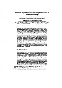
Performance of Stochastic Algorithm
[DeCarlo 2004]
The performance of the randomized algorithm across a flythrough involving several views is presented here. Using the lines from the previous frame as seeds had a fairly large impact, while another technique (walking “downhill” from the random seeds in search of a zero of radial curvature) shows limited improvement. Overall, very decent results can be obtained by testing 10% of the faces or less.
32
Using Graphics Hardware
Indexed by (sin2θ ) Dwκr /|w| →
Alternative algorithm: use texture mapping
Indexed by κr →
Use mipmapping for near-constant stroke width
Finally, there’s a way to use the graphics hardware to extract suggestive contours, similar to the use of texture maps indexed by (n dot v) to draw contours. The idea is to use a texture map with a dark line in part of it, with the horizontal texture coordinate indexed by radial curvature and the vertical coordinate indexed by the derivative (possibly with some sin(theta) terms as well). The dark part of the texture map will only be accessed if the radial curvature is near zero and the derivative is greater than zero (or some threshold). Note that in most cases the curvature and derivative will have to be computed “by hand” at each vertex, and the correct texture coordinates passed in.
33
Comparison of Effects
ConstantConstant-weight strokes
Strokes faded based on Dwκr
TextureTexture-map rendering [DeCarlo 2004]
Here’s a comparison of a few different algorithms. The first two images come from the object-space algorithm, with and without fading of strokes. The rightmost image was done using the texturemap-based algorithm.
34
Finding Ridges and Valleys Definition of ridges (valleys): – Local maxima (minima) of maximum (minimum) principal curvature, in corresponding principal direction
Some algorithms find extrema directly, while others look for zeros of derivative of curvature
Finally, let’s look briefly at algorithms for computing ridge and valley lines. Because these are defined in terms of high-order derivatives, which are often noisy, a big challenge is in getting good, robust estimates of these differential quantities.
35
Finding Ridges and Valleys Higher-order derivatives very sensitive to noise [Ohtake 04] uses implicit function fit, filters based on curvature integrated over length
A paper from last year achieved good results by computing the derivatives using implicit function fits, then doing some filtering on the resulting strokes.
36
Finding Ridges and Valleys [Pauly 03] looks for stable extrema over different scales of smoothing
Another interesting approach is to look for lines that are stable over different scales of filtering. This algorithm actually operates on unorganized point clouds, and doesn’t need a full mesh.
37