Proceedings of the International MultiConference of Engineers and Computer Scientists 2010 Vol II, IMECS 2010, March 17 - 19, 2010, Hong Kong
An Economical Rapid Control Prototyping System Design with Matlab/Simulink and TMS320F2812 DSP X. M. Chen, X. L. Gong, H. X. Zhou, Z. B. Xu, Y. G. Xu, and C. J. Kang
Abstract—Rapid control prototyping (RCP) is now the typical method used by engineers to develop and test their control strategies, but the commercial RCP systems are too expansive for researchers to use. This paper presents an economical RCP (eRCP) system based on MATLAB/Simulink and the Target Support Package TC2 toolbox. A TI TMS320F2812 DSP based real-time control board for 4 axes mechatronic system and data acquisition was developed for the eRCP system. The eRCP system has functions for symbolic model development, automatic code generation, variable monitoring, and parameter tuning. A complex controller for the linear motor driven double inverted pendulum (LMDDIP) was implemented by the eRCP system to demonstrate the performance of the developed system. Index Terms—Rapid control prototyping, TMS320F2812 DSP, MATLAB, double inverted pendulum.
I. INTRODUCTION Traditional controller development method has separated processes such as controller design, implementation, test and verification [1]. The whole process has to be restarted when occurring errors or divergences, which makes the development process time consuming and costly. Rapid Control Prototyping (RCP), however, is a process which executes every development processes under unified platform and lets engineers quickly test and iterate their control strategies on a real-time computer with real input/output devices [2]. Engineers can see results and iterate solutions rapidly before building expensive hardware. So RCP can eliminate potential bottlenecks, accelerate the development, and save costs, and it has been widely used in applications such as anti-lock braking, vehicle stability, flight control systems, navigation systems, servo-control, and medical device development [2]. Low cost rapid control prototyping systems are being used as teaching tools in most Manuscript received Sep. 26, 2009. X. M. Chen is with the University of Science and Technology of China, Hefei, CO 230027 China (e-mail:
[email protected]). X. L. Gong is with the University of Science and Technology of China, Hefei, CO 230027 China (corresponding author, phone: 86-551-3600419; fax: 86-551-3600419; e-mail:
[email protected]). H. X. Zhou is with the China Agricultural University, Beijing, CO 100086 China (e-mail:
[email protected]). Z. B. Xu is with the University of Science and Technology of China, Hefei, CO 230027 China (e-mail:
[email protected]). Y. G. Xu is with the University of Science and Technology of China, Hefei, CO 230027 China (e-mail:
[email protected]). C. J. Kang is with the University of Science and Technology of China, Hefei, CO 230027 China (e-mail:
[email protected]).
ISBN: 978-988-18210-4-1 ISSN: 2078-0958 (Print); ISSN: 2078-0966 (Online)
university graduate-level courses in classical and modern control theory. Until recently many commercial RCP products such as dSPACE, ConCurrent, RT- LAB, xPC, and CompactRIO are popular development partners in the automotive industry, aerospace and industrial automation. Almost all over the world, wherever engineers are working on cars and planes, dSPACE is involved [3]. Many researchers have created their own RCP system for different applications. Hong, Gan, Chong, Chew, Lee, and Koh, designed an implementation of digital signal processing algorithms using MATLAB and Texas Instrument TMS320C30 evaluation module [4]. Hercog and Jezernik presented a rapid control prototyping based custom made DSP using MATLAB/Simulink environment [5]. It provides a quick transition from the off-line simulation in Simulink to real-time operation on an embedded motor controller. Wootaik, Minsuk, and Myoungho proposed a “target identical” control prototyping platform for engine control that bases on an MPC555 controller [6]. Duma, Dobra, Abrudean, and Dobra developed a rapid prototyping of control system using embedded target for TI C2000 DSP to control a DC motor [7]. A problem with RCP system is the cost and complexity of the control hardware. A typical commercial rapid control prototyping system is typically around $30-45,000.00 depending on the vendor [2]. This entry level price is too expansive for many researchers to use. Most in-house designed RCP system is only for some plants or vehicles. To develop a more economical, powerful, and general RCP system, this study uses TI TMS320F2812 DSP based control board and the Target Support Package TC2 of MATLAB/Simulink to design a RCP system. A complex controller for linear motor driven double inverted pendulum (LMDDIP) was implemented by the eRCP system to demonstrate the capabilities of the developed system.
II. ARCHITECTURE OF THE PROPOSED RAPID CONTROL PROTOTYPING SYSTEM A typical rapid control prototyping system is comprised of a math modeling program, a real-time development environment, a real-time target computer, a host computer, and a Graphical User Interface (GUI) application. In this design, MATLAB/Simulink was used as a real-time development. Matlab/Simulink is a design and simulation tool used at many universities and numerous industrial IMECS 2010
Proceedings of the International MultiConference of Engineers and Computer Scientists 2010 Vol II, IMECS 2010, March 17 - 19, 2010, Hong Kong
Modeling and Simulation
Input/Output Blockset
The following sections will introduce the hardware and software design in detail. Model to Hardware Interface III. HARDWARE DESIGN Code Generation
Development Environment
Host Computer Tuning Parameters Variable Monitoring
GUI Application
Real-Time Target Control Board
Fig.1 Architecture of the eRCP System
companies. Simulink is a graphical environment which allows the user to create models for dynamic systems simply by connecting blocks from available libraries. Real-Time Workshop technology of the Simulink supports rapid prototyping by providing a framework for running generated code in real time, tuning parameters, and monitoring real-time data [8]. A TI TMS320F2812DSP was adopted to develop a real-time target control board. It integrates powerful peripherals and is supported seamlessly by the MATLAB, which can greatly simplify the design of the eRCP system. As a typical RCP system, the architecture of the eRCP system is shown in Fig.1. The development procedure is as follows [2], [8]: 1) Modeling, developing control strategy, and carrying out simulation using MATLAB/ Simulink; 2) Importing Input/Output blocks into control strategy simulation Simulink model so as to creating a real-time Simulink model that can be runs in real time on rapid control prototyping hardware; 3) Using Real-Time Workshop system target files to generate code that can be deployed onto the real-time target control board; 4) Monitoring signals, tuning parameters, and logging data using GUI application;
10 9
3
4
2
5 1
8
7
6
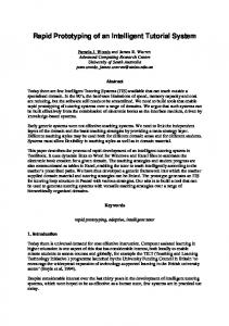
1. TMS320F2812 DSP 2. RS232 3. CAN 4. DAC 5. Encoder 6. ADC 7. IO 8. JTAG 9. Emulator 10. USB Fig.2 Hardware of the Rapid Control Prototyping System
ISBN: 978-988-18210-4-1 ISSN: 2078-0958 (Print); ISSN: 2078-0966 (Online)
The DSP control board depicted by Fig.2 is in-house developed for 4 axes mechatronic system and data acquisition. The features of the control board are shown as follows: 1) The control board is built around high performance 32-bit microcontrollers TI TMS320F2812DSP with high performance integrated peripherals designed for real-time control applications. Its optimized core can run multiple complex control algorithms at speeds necessary for demanding control applications [9]; 2) Powerful peripherals combined with 4 channels 16-bits ADC, 8 channels 12-bits ADC, 4 channels 16-bits DAC , UART, CAN, 4 interfaces for incremental encoders, 2 digital inputs and 6 digital outputs, which makes the control board a good control solution and data acquisition; 3) Using Real-Time Data Exchange (RTDX) transfers data between a host computer and DSP target applications through XDS510 USB JTAG Emulator. RTDX enables real-time, asynchronous exchange of data between target and host without halting or stopping the target processor. The RTDX is capable of data rates over 10K Bytes per second [10]; 4) The TI TMS320F2812DSP integrates 128K x 16bit flash device so that the generated code can be downloaded to the flash for standalone operation in embedded controller applications, and the control board can be designed as standalone electronic control unit for user’s product because of its low cost. Fig.2 displays the hardware of the rapid control prototyping system.
IV. SOFTWARE DESIGN The key feature of the RCP is that rapid control prototyping algorithms are developed as symbolic models, not as C-code. The program which is running in the target control board can be controlled by a graphical user interface application. The software design is very important to realize these functions. To develop an easy-to-use and economy rapid controll prototyping system, this study took the advantage of the Target Support Package TC2 for TI TMS320C2000 DSP of MATLAB 2008a. The toolbox integrates the MATLAB® and Simulink® with TI's eXpressDSP™ tools and C2000™ processors. Together, these products let user develop and validate control designs and digital signal processing algorithms from concept through code by performing automatic code generation, prototyping, and embedded system deployment on TMS320C2000 processors. By using the toolbox, it can generate a C-language real-time implementation of control algorithm in the form of Simulink model. It can automatically compile, link, download, and execute the generated code on the control card. TMS320C2000 DSP peripherals are directly supported in the
IMECS 2010
Proceedings of the International MultiConference of Engineers and Computer Scientists 2010 Vol II, IMECS 2010, March 17 - 19, 2010, Hong Kong
toolbox. The generated code is readable and editable with Real-Time Workshop Embedded Coder [8]. There are only “To RTDX” and “From RTDX” blocks in the Target Support Package TC2 instead of visual interface, so it is necessary to design a graphical user interface to control the real-time process. The software design of the eRCP includes the following four aspects: A. Real-time Input/output Simulink Blocks There are no 16-bits ADC, 4 channels 16-bits DAC, and 2 incremental encoder blocks in the Target Support Package TC2, so the drive code of the extended peripherals should be integrated into Simulink blocks and added into the toolbox. The Real-Time Workshop toolbox was used for integrating drive code to the real-time input/output Simulink blocks. The original TMS320F2812 DSP peripherals blocks and the developed blocks are shown as follows:
Fig.4 Variable Display Simulink Blocks Fig.4 shows the variable display Simulink blocks: The first two rows blocks are real-time Simulink blocks, and they have an input port to be “wired” to the observation point. Every block has a “To RTDX” block, after it is generated executable code to the DSP, the program can establish a RTDX channel to send variable data to the graphical user interface application through emulator and USB cable; the last two rows blocks are user interface Simulink blocks, and they integrate MATLAB m-code used to establish RTDX communication to receive variable data sent by the DSP and display the variable data graphically. The real-time Simulink blocks and the user interface Simulink blocks are one-to-one correspondence through the block name, for example, if “WM-Read1”is used to in real-time Simulink model to send data, in graphical user interface application, the “WM_Read1” block should be used to receive the data.
Fig.3 Real-time Input/output Simulink Blocks The first three rows blocks are original TMS320F2812 DSP peripherals blocks, the forth row blocks are 16-bits ADC real-time blocks, the fifth row blocks are 16-bits DAC real-time blocks, and the last row blocks are encoder real-time blocks. All these blocks are interface with the corresponding peripherals on the control board. B. Variable Monitoring and Parameter Tuning Simulink Blocks In the eRCP, a graphical user interface application was developed to control and monitor the running program on the control board and it makes the development of controllers more effective. The graphical user interface application developed via Simulink software comprises of variable display Simulink blocks and parameter tuning Simulink blocks. These blocks can be divided into two types: real-time blocks used in real-time Simulink model and user interface Simulink blocks used in graphical user interface application.
ISBN: 978-988-18210-4-1 ISSN: 2078-0958 (Print); ISSN: 2078-0966 (Online)
Fig.5 Parameter Tuning Simulink Blocks Fig.5 shows the parameter tuning Simulink blocks: The first two rows blocks are real-time Simulink blocks used as “Gain” blocks, and the value of the gain is set by graphical user interface application. The output value is equal to the input multiplied by the value of gain. Every block has a “From RTDX” block, after it is generated executable code to the DSP, the program can establish a RTDX channel to receive parameter set by the graphical user interface application through emulator and USB cable; The last two IMECS 2010
Proceedings of the International MultiConference of Engineers and Computer Scientists 2010 Vol II, IMECS 2010, March 17 - 19, 2010, Hong Kong
rows blocks are user interface Simulink blocks, and they integrate MATLAB m-code used to establish RTDX communication to send parameter to the DSP. The real-time Simulink blocks and the user interface Simulink blocks of parameter tuning Simulink blocks are also one-to-one correspondence through the block name, for example, if “WM-Write1”is used to in real-time Simulink model to receive data, in graphical user interface application, the “WM_ Write1” block should be used to send the data. C. Code Generation Process Control Simulink Blocks Fig.6 is code generation process control Simulink blocks, and these blocks are used in graphical user interface application to control the code generation process for the user. Double clicking “WM Model Run” block can start the build process: translate real-time Simulink model to C-code, setup a project file for code composer studio (CCS) for the TMS320F2812 DSP board, CCS cross-compiler to build the project and generate a executable file that is automatically downloaded via the USB interface and emulator to the target DSP. After downloading the executable file to the target, the build process runs the file on the board's DSP. Double clicking “WM DSP Reset” block can reset target DSP whether it is running or not. All these functions are realized by MATLAB m-code integrated into the blocks.
Fig.6 Code Generation Process Control Simulink Blocks
V. APPLICATION To illustrate the performance and the direction for use of the proposed RCP system, a rapid prototyping of LQR controller for the linear motor driven double inverted pendulum (LMDDIP) was implemented. The inverted pendulum is a classic problem in control systems, characterized by its high order, instability, multivariable, nonlinear, strong coupling and underactuated characteristic. The LMDDIP was adopted to demonstrate the capability of the RCP system for the following reasons: The algorithm design, off-line simulation, implementation, and optimization for the real-time control of the LMDDIP are good examples for the typical development procedure of the RCP. The LMDDIP is inherently unstable, and must be actively balanced in order to remain upright, if the control program is stopped, the pendulum will fall down, so the usual Stop-Mode debugging can not be used to debug the program, while the RCP system can give designers continuous, real- time visibility into their applications. The RCP development process of the LMDDIP goes as follows: A. Modeling and Develop Control Strategy Using Simulink
ISBN: 978-988-18210-4-1 ISSN: 2078-0958 (Print); ISSN: 2078-0966 (Online)
Fig. 7 Photograph of the LMDDIP
As shown in Fig.7, the LMDDIP is made up of linear motor, bottom pendulum, top pendulum, cart, linking mechanism between top pendulum and bottom pendulum, linear encoder and rotary encoder. The math model of the LMDDIP was deduced first and the control strategy (linear quadratic regulator) was developed using MATLAB/Simulink, and then the math model and the control strategy were tested and optimized in a simulation environment. Fig.8 shows the Simulink model used to simulate the LMDDIP: The State-Space block contains the LMDDIP motion equations. The initial parameters of the controller were obtained by simulation. The value will be adjusted in real-time control to achieve better control performance when the application is running.
Controller -K k1 -K -
Input
Plant x' = Ax+Bu y = Cx+Du
Step
State -Space
k2 -K k3 -K k4 -K k5 -K k6
Fig.8 Simulation Simulink model of LQR controller B. Develop Real-time Simulink Model Symbolic input/output (I/O) device interface blocks were imported into the Simulink model. This was a symbolic way to add input/output capability to the control strategy. The parameters tuning blocks and the variables monitoring blocks should be also “wired” to the appropriate points.
IMECS 2010
Proceedings of the International MultiConference of Engineers and Computer Scientists 2010 Vol II, IMECS 2010, March 17 - 19, 2010, Hong Kong
Fig. 9 LQR controller for the LMDDIP
Fig.9 shows the Simulink model used for generation of the executable code. “F2812 eZdsp” is a processor preference of TMS3202812 DSP for the model; “Encoder1”, “Encoder4” and “Encoder2” are QEP (Quadrature Encoder Pulse) blocks which are used to collect the signals of the displacement of the cart, the angle of the bottom pendulum and the angle contained by the top pendulum and bottom pendulum respectively. “WM-DAC_1” is the digital-to-analog conversion block. “Gain3” is the pulse equivalence of the linear encoder, while “Gain1” and “Gain2” are the pulse equivalence of the rotary encoder, and the “Encoder1” block’s output physical unit is meter, while the “Encoder4” and “Encoder2” blocks’s units are radian, which is the same as the state variables of the LMDDIP’s state equation; “WM-Write1”, “WM-Write2”, “WM-Write3”, “WM-Write4”, “WM-Write5”, and “WM-Write6” are the values of the feedback matrix K which are obtained in Simulation, and blocks’ value can be changed by the graphical user interface when the application is running. The value calculated by the LQR algorithm is passed to “WM-DAC_1” block; “WM-Read1” is used to observe the cart ‘s displacement; “WM-Read2ab” is used to observe the angle of the bottom pendulum and the top pendulum; “WM Model Run” is a button allowing user to start building the model to generate executable code.
Fig. 10 Graphical user interface for the LMDDIP ISBN: 978-988-18210-4-1 ISSN: 2078-0958 (Print); ISSN: 2078-0966 (Online)
After building the Simulink model, C-language real-time implementation of control algorithm for DSP control card will be generated, and the generated code will be automatically compiled, linked, downloaded, and executed on the control card. C. Set up Graphical User Interface application To observe the behavior of the real-time application and to change application-specific parameters, a graphical user interface was set up as shown in Fig.10. “WM_Write1”, “WM_Write2”, “WM_Write3”, “WM_Write4”, “WM_Write5”, and “WM_Write6” blocks are used to change the values of the feedback matrix K that are set in Simulation Model; “WM_Read1” is used to display the cart ‘s displacement; “WM_Read2ab” is used to display the angle of the bottom pendulum and the angle of the top pendulum. D. Code Generation and Real-time Operation With above configuration, a real-time executable code can be generated and downloaded into the TMS3202812 DSP based control card by clicking “WM Model Run” button on the real-time Simulink model, and the build process does the following: 1). The real-time Simulink model is “read” and Real-Time Workshop software automatically generates C-code and inserts the I/O device drivers as specified by the hardware blocks in the real-time Simulink model; 2). The generated C-code is “cross” compiled and linked with the TMS3202812 DSP target code such as a scheduler, I/O routines, and communication routines specific to the real-time target; 3). An executable program for the TMS3202812 DSP is generated and downloaded to the DSP, and then the build process runs the file on the DSP; E. Tuning Parameters and Monitoring Variables After running the generated application, the graphical user IMECS 2010
Proceedings of the International MultiConference of Engineers and Computer Scientists 2010 Vol II, IMECS 2010, March 17 - 19, 2010, Hong Kong
interface can be run to control the application. The graphical user interface application is user’s window into the real-time operation of the control strategy. Variables can be monitored, graphed, or logged. The strategy can be altered only by “tuning” gains – the structure of the strategy cannot be changed. For example, if other control strategy is taken to control the LMDDIP, the real-time Simulink model has to be changed and the build process repeated. Fig.11 shows a running graphical user interface application. The LMDDIP has been successfully controlled by the eRCP system. The six parameters of the feedback matrix can be changed on-line, and the cart’s position and the pendulums’ angle can be display graphically.
between a host computer and a DSP target applications and simplify the system design. The eRCP system was successfully used to control the complex LMDDIP, which demonstrates the ability to realize RCP development method and solves the control problems of high order, instability, multivariable, nonlinear, and strong coupling. Using this system, the design of electrically controlled unit is efficient so that the designers can place more focus on creative solution of control algorithm or engineering problems rather than the software and hardware implementations of the control algorithm. The low cost of the eRCP system makes it available for most control researchers to accelerate the development of control system.
Top Pendulum’s Angle Bottom Pendulum’s Angle
REFERENCES [1]
Cart’s Position Real-time Simulink Tuning Parameter
Graphical User Interface
[2] [3]
[4]
[5]
Fig. 11 Graphical user interface for the LMDDIP
VI. CONCLUSIONS This paper proposed an eRCP system that has functions for symbolic model development, automatic code generation, variable monitoring, and parameter tuning. The real-time target computer for the eRCP system is the TI TMS320F2812 DSP based control board designed in-house, and it can run multiple complex control algorithms at speeds necessary for demanding control applications, and powerful peripherals of the control board make it capable of controlling 4 axes mechatronic system and data acquisition. Especially using RTDX can establish communication
ISBN: 978-988-18210-4-1 ISSN: 2078-0958 (Print); ISSN: 2078-0966 (Online)
[6]
[7]
[8] [9]
J. Jang, C. K. Ahn, S. Han, and W. H. Kwon, “Rapid Control Prototyping for Robot Soccer System using SIMTool,” in Proc. SICE-ICASE International Joint Conference 2006, Busan, Korea, Oct. 2006, vol. 2, pp. 3035–3039. PrecisionMBA, LLC. “Rapid Control Prototyping,” Available: http://www.precisionmba.com/rapid_control_prototyping.htm dSPACE Inc. “Company Profile,” Available: http://www.dspaceinc.com/ww/en/inc/home/company/company_profil e.cfm?nv=n1 K. H. Hong, W.S. Gan, Y. K. Chong, K. K. Chew, C. M. Lee, and T. Y. Koh, “An Integrated Environment for Rapid Prototyping of DSP Algorithms using Texas Instruments TMS320C30,” Microprocessors and Microsystems, vol. 24, no. 7,pp. 349-363, Nov. 2000. D. Hercog and K. Jezernik, “Rapid Control Prototyping MATLAB/Simulink and a DSP-Based Motor controller,” Int. J. Eng. Ed., vol. 21, no. 4, pp. 596-605, 2005. L. Wootaik, S. Minsuk, and S. Myoungho, “Target-Identical Rapid Control Prototyping Platform for Model-Based Engine Control,” J. Automobile Engineering, vol. 218, no. 7, pp. 755-765, July 2004. R. Duma, P. Dobra, M. Abrudean, and M. Dobra, “Rapid Prototyping of Control Systems using Embedded Target for TI C2000 DSP,” 2007 Mediterranean Conference on Control and Automation, Athens, Greece, July, 2007, pp. 1-5. Real-Time Workshop User’s Guide, The MathWorks, Inc., Natick, MA, USA, Version 7.3, Mar. 2009. TMS320F2812 datasheet, Texas Instruments Incorporated.
Available: http://focus.ti.com/docs/prod/folders/print/tms320f2812 .html [10] RTDX 2.0 users guide, The MathWorks, Inc., Natick, MA, USA, Oct. 2007.
IMECS 2010