An Efficient Alias-free Shadow Algorithm for Opaque and Transparent Objects using per-triangle Shadow Volumes Erik Sintorn∗ Chalmers University Of Technology
Ola Olsson† Chalmers University Of Technology
Ulf Assarsson‡ Chalmers University Of Technology
(b)
(c)
(a)
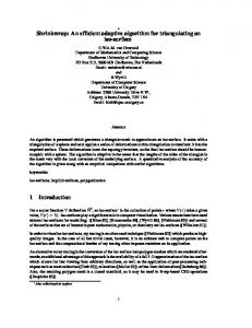
Figure 1: Images rendered with the novel shadow algorithm. All images rendered in 1024x1024, time taken to generate shadow buffers in parenthesis. (a) Pixel accurate hard shadows in a game scene (7.29ms, 60k triangles). (b) Alpha-textured shadow casters (13ms, 35k triangles). (c) Colored transparent shadows. Image rendered using depth peeling of 8 layers (75.66ms, 5-19 ms per layer, 60k triangles).
Abstract
Links:
This paper presents a novel method for generating pixel-accurate shadows from point light-sources in real-time. The new method is able to quickly cull pixels that are not in shadow and to trivially accept large chunks of pixels thanks mainly to using the whole triangle shadow volume as a primitive, instead of rendering the shadow quads independently as in the classic Shadow-Volume algorithm. Our CUDA implementation outperforms z-fail consistently and surpasses z-pass at high resolutions, although these latter two are hardware accelerated, while inheriting none of the robustness issues associated with these methods. Another, perhaps even more important property of our algorithm, is that it requires no pre-processing or identification of silhouette edges and so robustly and efficiently handles arbitrary triangle soups. In terms of view sample test and set operations performed, we show that our algorithm can be an order of magnitude more efficient than z-pass when rendering a gamescene at multi-sampled HD resolutions. We go on to show that the algorithm can be trivially modified to support textured, semitransparent and colored semi-transparent shadow-casters and that it can be combined with either depth-peeling or stochastic transparency to also support transparent shadow receivers. Compared to recent alias-free shadow-map algorithms, our method has a very small memory footprint, does not suffer from load-balancing issues, and handles omni-directional lights without modification. It is easily incorporated into any deferred rendering pipeline and combines many of the strengths of shadow maps and shadow volumes.
1
CR Categories: I.3.7 [Computer Graphics]: Three-Dimensional Graphics and Realism—Color, shading, shadowing, and texture; Keywords: shadows, alias-free, real time, transparency ∗ e-mail:
[email protected]
† e-mail:
[email protected] ‡ e-mail:
[email protected]
DL
PDF
Introduction
Generating accurate shadows from point light-sources for each pixel sample remains a challenging problem for real-time applications. Despite generations of research, we have yet to see a pixel-accurate shadow-algorithm for point lights that requires no pre-processing, works on any arbitrary set of triangles and that runs at stable real-time frame rates for typical game-scenes on consumer level hardware. Traditional shadow mapping [Williams 1978] techniques generate shadows from a discretized image representation of the scene and so alias when queried for light visibility in screen space. Real-time techniques based on irregular rasterization [Sintorn et al. 2008] tend to generate unbalanced workloads that fit current GPUs poorly and consequently, frame rates are often very unstable. Real-time ray tracing algorithms rely heavily on geometry pre-processing to generate efficient acceleration structures. Finally, robust implementations of the Shadow-Volume algorithm require pre-processing the mesh to find edge connectivity, work poorly or not at all for polygon soups without connectivity, and have frame rates that are all but stable as the view of a complex scene changes. Nevertheless, the idea of directly rasterizing the volumes that represent shadows onto the view samples remains compelling. In the
upcoming sections, we hope to convince the reader that this basic idea is sound and that choosing the right manner of rasterization is the key to efficiently generate shadows using shadow volumes.
also propose a scheme to anti-alias the shadow-edges without actually using more than one depth-value per pixel in the depthhierarchy. This method is equivalent to PCF filtering of an infinite resolution shadow map and like PCF filtering gives occasionally incorrect but visually pleasing results.
2
Figure 2: A point lies in the shadow volume of a triangle if it lies behind all planes CAB, DAC, BAD and BCD. To optimize culling of tiles, let E be the eye position and test against the planes EDA and EAB, in order to get a less conservative tile-test (see Section 3.5) . These two planes are depicted with red dashed lines. The basic algorithm described in this paper can be easily summarized. We render the shadow volume of each triangle, see Figure 2, onto a depth buffer hierarchy generated from the standard depth buffer after rendering the camera view of the scene. A node in this hierarchy is a texel at some level, containing the min and max depths and defines a bounding box in normalized device coordinates (see Section 3). To avoid confusion with traditional shadow volumes, which represent shadows from an object, we will refer to our single triangle shadow volumes as shadow frustums. A shadow frustum can either intersect a node, in which case the child-nodes must be inspected; completely envelop a node, in which case the node and all its child-nodes are in shadow and can be flagged as such; or the node can lie completely outside the frustum, in which case all child-nodes can be abandoned. We have implemented this algorithm in CUDA, where it takes the form of a hierarchical rasterizer operating on shadow frustum primitives. The algorithm has many things in common with the traditional Shadow-Volume algorithm, but by considering every shadow frustum separately (as opposed to forming the shadow volume from the silhouette edges of an object) and by maintaining the complete frustum throughout traversal (as opposed to splitting it into per-edge shadow-quads), we manage to elegantly steer clear of the many quirks and robustness issues that are associated with other Shadow-Volume algorithms.
Previous Work
For a thorough overview of real-time shadow algorithms, we refer the reader to [Eisemann et al. 2009]. Below, we will review the work most relevant to the algorithm presented in this paper. Algorithms for rendering hard shadows in real-time can be roughly sorted into three categories: Today shadow mapping [Williams 1978] and related techniques constitute the de-facto standard shadowing algorithm for real-time applications, despite suffering from quite severe aliasing artifacts. This widespread adoption has come about due to good hardware support, ability to handle arbitrary geometry, and low variability in frame times. Shadow mapping
Another reason for the popularity is that the shadow map can be filtered to hide artifacts, mimicking the effect of an area light-source. Filtering during lookup usually requires a large number of samples [Reeves et al. 1987; Fernando 2005], whereas pre-filtering requires additional attributes, which increases storage and bandwidth requirements [Donnelly and Lauritzen 2006; Annen et al. 2008]. Filtering can enable the use of relatively low resolution shadow maps while producing visually pleasing results.
• works for any arbitrary triangle-soup without pre-processing.
However, without resorting to a very high-resolution shadow map, sharp shadows cannot be produced, leaving shadows artificially blurred or with obvious discretization artifacts. Several algorithms attempt to improve precision where it is most needed, without abhorrent memory requirements, either by warping or by partitioning the shadow map. Warping techniques [Stamminger and Drettakis 2002; Wimmer et al. 2004; Lloyd et al. 2008] can yield impressive results but suffer from special cases where they degenerate to ordinary shadow maps. Partitioning approaches can produce highquality sharp shadows quickly for some scenes [Arvo 2004; Zhang et al. 2006; Lefohn et al. 2007; Lauritzen et al. 2011], but have difficulties if the scenes are very open with widely distributed geometry, leading to aliasing re-appearing, unpredictable run-time performance, or escalating memory requirements.
• is demonstrated to be very efficient in the amount of work performed per shadowed view sample.
Alias-free shadow maps
Our main contribution is an accurate and efficient algorithm for determining light source visibility for all view samples which:
• has a very low memory footprint. • trivially extends to allow for textured shadow-casters. • trivially extends to allow for semi-transparent and colored semi-transparent shadow-casters. • is easy to integrate into any deferred rendering pipeline. We show that the shadow frustum–depth hierarchy traversal, as well as interpolation of per-vertex attributes, can be done entirely in homogeneous clip space, thereby eliminating any potential problems with near and far clip planes. Additionally, we suggest a novel method where binary light visibility is recorded stochastically per view sample with a probability equal to the opacity of the shadow-casting triangle. This allows us to store a single bit of visibility information per sample in Multi-Sample Anti Aliasing (MSAA), Coverage-Sample Anti Aliasing (CSAA) or SuperSample Anti Aliasing (SSAA) rendering contexts and still get a correct-on-average visibility result when the pixel is resolved. We
Alias-free shadow-mapping algorithms are exact per view sample [Aila and Laine 2004; Johnson et al. 2005; Sintorn et al. 2008]. To our knowledge, the only pixel accurate alias-free shadow algorithm that runs in real-time on current GPUs for complex scenes is [Sintorn et al. 2008]. While this algorithm runs admirably on some scenes and is likely to perform as well as or better than ours on views with a very high variance in the depth buffer, it breaks down in other configurations (e.g. when all view samples project to a single line in light space). Like our algorithm, these exact methods could trivially support semi-transparent and textured shadow casters. The Shadow-Volume algorithm, introduced by Crow in [1977], was implemented with hardware acceleration in 1985 [Fuchs et al. 1985] but did not see widespread use until a version was suggested that could be hardware accelerated on consumer grade graphics hardware with the z-pass algorithm [Heidmann 1991]. The idea is to isolate the silhouette-edges and extrude these away from the light-source, forming shadow-quads that enclose the shadow volume for an object. These shadow volumes are Shadow volumes
rendered onto the camera’s depth buffer and the stencil buffer is incremented for front-facing quads and decremented for back-facing so that, when all quads are processed, the stencil buffer value will be 0 only for those pixels that do not lie in shadow. This essentially creates a per-pixel count of the number of shadow volumes that are entered by a ray cast from the eye to the view sample. Alternatively, the counting can be performed from the view samples to infinity, a method called z-fail [Bilodeau and Songy 1999; Carmack 2000]. Z-pass classically suffers from the eye-in-shadow problem, i.e. if the camera lies within one or more shadow volumes, or if the nearplane clips any shadow quad, the values in the stencil buffer will be incorrect. This is partly solved by Hornus et al. [2005] where the lights’ view is aligned with that of the camera and the light’s far plane is set to equal the camera’s near plane. Since the light is not in shadow, the scene can then be rendered from the light with a projection matrix set up to match that of the camera, and the stencil buffer is updated with all shadow quads that lie between the light and the camera near plane in a first pass. The algorithm has some robustness issues that get worse as the lights’ position approaches the cameras near plane. With the advent of depth-clamping, the solution to the eye in shadow problem is reduced to evaluating how many shadow casters lie between the camera and light, but to date no fully robust solution has been presented to this problem. While the z-fail algorithm can be made practically robust [Everitt and Kilgard 2002], it is typically significantly slower due to higher overdraw [Laine 2005] and the need for near- and far capping geometry. An eight-bit stencil buffer (still the maximum allowed on current GPUs) can overflow, and resorting to using higher-precision color buffers will accentuate the rasterization cost significantly. Several papers exist that aim to reduce fill rate requirements. In [Lloyd et al. 2004], the authors consider the objects in a scene graph and discuss a number of ways to prune the set of objects to find potential shadow-casters (for the current light view) and potential shadow receivers (for the current camera view). They also suggest a way to limit the distance a shadow caster has to extend its shadow volume in order to conservatively reach all potential shadow receivers. All of the optimizations in this paper are equally applicable to our algorithm (if we were to include a far plane for our shadow frustums), but as our rasterization already culls receiving tiles much more efficiently than the z-pass or z-fail algorithms, the overdraw reductions would probably not be large. Aila and Akenine-Moller [2004] suggest an optimization that in some ways resemble ours. In the first stage of their algorithm, 8x8 pixel tiles that lie on the shadow-volume boundary are identified (a minimum and maximum z for each tile is maintained, and thus, the 3D bounding box for the tile can be tested against each shadow-quad) and other tiles are classified as either fully in shadow or fully lit. One such shadow buffer (containing a boolean boundary flag and an eight-bit stencil value) is required per shadow volume. In the second stage, the per pixel shadow is calculated for boundary tiles whereas non-boundary tiles can be set to the shadow state of the tile. The authors suggest two hardware modifications to make the algorithm more efficient: a hierarchical stencil-buffer that would make classification of tiles faster and a so called Delay Stream that would help the rasterizer keep track of when the classification of a shadow volume is complete and final stencil buffer updates can begin. Nevertheless, this solution would be infeasible for a larger amount of shadow volumes. Chan and Durand [2004] use a shadow map to fill in the hard shadows and also identify shadow-silhouette pixels. Then, shadow volumes are used to generate correct shadows at these silhouette pixels. However, the algorithm relies on custom hardware to reject non-silhouette pixels and cannot guarantee not missing small silhouettes due to the discrete shadow map sampling.
Materials that are semi-transparent are common in real-time applications and present a problem for most shadow algorithms. A semi transparent surface is given an alpha or opacity value, α, which is defined as the ratio of received light that is absorbed or reflected at the surface (1 − α is the ratio that continues through the surface). This same model is commonly used to represent both materials that have partial coverage (e.g. a screen door) and materials that transmit light (e.g. thin glass) [McGuire and Enderton 2011]. For shadow-map based methods, these materials are difficult because a visibility lookup is no longer a binary function and so, a single depth value is not sufficient to define the visibility along a ray from the light towards the point being shadowed. Several techniques have been suggested to solve this by rendering shadow maps with several layers, the most common being Deep Shadow Maps [Lokovic and Veach 2000] for which the scene has to be rendered several times in the absence of a hardware accelerated A-buffer [Carpenter 1984], or by sampling visibility at discrete depths [Kim and Neumann 2001; Yuksel and Keyser 2008; Sintorn and Assarsson 2009] which works well for ”fuzzy” geometry such as smoke or hair, but not so well for polygons where strong transitions in visibility happen at every surface. Recently, a different method was proposed [Enderton et al. 2010; McGuire and Enderton 2011] in which, when generating the shadow map, a triangle fragment is simply discarded with probability (1 − α). A PCF lookup into this map will return a value that is correct on average. However, if too few taps are taken from the filter region, the result will be noisy and so, to achieve sharp and noise free shadows, very many taps will be required from a very high resolution shadow map. Textured and semi transparent shadows
Semi-transparent shadows have been considered for shadowvolume type algorithms as well. A straightforward approach was suggested in [Kim et al. 2008], where the stencil buffer is replaced by a floating point buffer and the stencil increment/decrement operations are replaced by adding or removing log(1 − α), where α is the opacity of the object that generated the shadow quad. ThisQelegantly produces a final stencil value, s, such that exp(s) = i (1 − αi ), where αi is the opacity value of a shadow caster that covers the sample point, which is exactly the visibility at that point. The method produces pixel-accurate sharp shadows and can easily be extended to support colored shadow-casters, but requires opacity to be constant per object. Needless to say, the additional math and blending operations exacerbate the overdraw problem inherent in the traditional Shadow-Volume algorithm. Also, textured shadow casters are not supported. In [Hasselgren and Akenine-Moller 2007] the problem is instead solved simply by handling semi-transparent or textured objects separately, so that every triangle shadow volume is rendered for such objects. Despite the optimizations discussed in that paper, this will cause very much overdraw and will be prohibitively slow for complex geometry. The realization from that paper, that transparent and textured shadow casters are easily supported when the triangles’ shadow volumes are handled separately, is, however, the basis for these extensions to our algorithm which renders per-triangle shadow volumes very efficiently. It should also be mentioned that a similar idea was used for textured soft shadows [Forest et al. 2009]. In games and other real-time graphics applications, complex geometry is often approximated by mapping a binary alpha mask to simple geometry. A common example is the leaves on the tree in Figure 1(b). Casting shadows from such objects is simple when using shadow-mapping type algorithms, where, when rendering the shadow map, a fragment can simply be discarded if the alpha value is below some threshold. Unfortunately, as the filtered opacity value will not be binary even if the original alpha mask is, this technique introduces even more aliasing to the shadow-map algorithm. The problem with shadow casters of this kind, when using shadow-
volume type algorithms, is that when a shadow-quad is rendered over a view sample, we know only that the sample lies within the shadow volume of some object but we have no means of determining which triangle covers the sample, and so, we cannot do a lookup into the alpha mask to see if the point is truly in shadow. If we render triangle shadow volumes individually however (as in [Hasselgren and Akenine-Moller 2007]), we may pass along the uv coordinates of each vertex, as well as the vertices themselves, and then do a ray-triangle intersection test prior to updating the stencil buffer, or by some other means find the uv coordinates on the triangle.
Figure 3: Every texel in the second level of the depth hierarchy defines a bounding box in normalized device coordinates and, equivalently, a world space frustum which contains all view samples inside.
3
Algorithm
We start out with as basic an approach to shadow volumes as we can imagine. The scene has been rendered to an off-screen set of buffers containing the ambient light component, direct lighting and the depth buffer. The depth buffer, along with the model-viewprojection matrix, implicitly gives us the position of a point on a ray shot from the camera through the mid-sample of each pixel, at the closest triangle intersection. We call these positions view samples and they are the points for which we want to evaluate shadow (i.e. we want to evaluate whether these points are visible from the light source or not). We can do this by testing, for every view sample, whether it lies within the shadow frustum (i.e. the shadow volume of the triangle). If so, the sample is marked as shadowed in a separate buffer requiring a single bit per pixel. We will call this buffer the shadow buffer in the discussion below. To evaluate whether the sample is within the volume or not is a matter of testing the point against the four planes that make up the volume (See Figure 2). While exhaustively testing all view samples against all triangle volumes is obviously not a good idea in practice, it is worthwhile to note a few things about this naive algorithm:
level. A texel’s (x, y) coordinates and these two depths then define an axis aligned bounding box in normalized device coordinates (or a bounding-frustum in world space, see Figure 3), for the view samples contained within. We will refer to such bounding-frustums as tiles from here on. Our imaginary rasterizer takes a triangle and a light-source position as input and rasterizes the projected shadow volume. The main difference in how our rasterizer works, compared to how shadow quads are traditionally rasterized, lies in the way that we cull against the hierarchical depth buffers. Where a traditional rasterizer will cull a number of fragments of a shadow quad only if they all lie in front of the min depth stored in the upper level of the hierarchy (for z-fail), our rasterizer tests the tile against each plane of the shadow frustum. If the tile is found to lie outside either plane, it can be culled and no bits will be set for the contained view samples in the shadow buffer. Additionally, if the tile is found to lie inside all planes, we know that all contained view samples are covered by this triangle, and so, we simply set a bit in the higher level of our hierarchical shadow buffer and can then safely abandon the tile. If the bounding-box can not be trivially rejected nor accepted, the individual view samples will be tested against the shadow volume planes and the lower level of the shadow buffer is updated. Before the shadow buffer is used to determine whether a pixel should be considered in shadow or not, the two levels must be merged. This is done by, for each set bit in the higher level, also setting the corresponding 4x4 bits in the lower level, regardless of their current state. For the algorithm to be perfectly robust, two things must be considered. First, if an edge is shared by two triangles, a view sample will be tested against the same plane twice, only with opposite normals. If the sample lies very close to the plane, we can get the erroneous result that the sample lies outside both, unless we make sure that the equations for these planes are constructed in exactly the same way, which may not happen if we simply use the vertices in the order they are submitted. Instead, when constructing a plane from the light’s position and two edge vertices, the vertices are taken in an order defined by their world space coordinates (any unique ordering will do). Similarly, for a perfectly robust solution, testing whether a sample lies below the plane formed by the triangle should be done exactly in the same way as when the original depth buffer value was created. A hardware vendor could ensure that this is the case, but our software implementation must resort to adding a bias to the triangle plane to avoid self shadowing artifacts. Unlike the bias required for shadow maps, this bias can be very small and constant and in practice it does not introduce any noticeable artifacts.
• It works without modification for any arbitrary triangle soup.
3.1
• It will be robust as long as some precautions are taken (see paragraph on robustness below)
To evaluate the new algorithm, we have designed a hierarchical shadow volume rasterizer and implemented the design in software using NVIDIA’s CUDA platform. We chose a fully hierarchical approach because this is the most viable known approach to parallel SIMD software rasterization [Abrash 2009], while for a hardware implementation it is likely that a two-level stamp rasterizer would prove more efficient.
• It requires a very small amount of extra memory storage (a single bit per view sample). • It requires no pre-processing nor does it matter where the light, camera near or far planes are situated. • When a pixel has been marked as in-shadow, it need no longer be considered by other triangle shadow volumes. Let’s consider what could be done to alleviate the overdraw problems in an imaginary customized stamp rasterizer with a two-level hierarchical depth buffer and an equally sized two-level hierarchical shadow buffer (which can be thought of as a one bit stencil buffer). Let’s say the upper level of the hierarchical depth buffer contains the min and max of the 4x4 depth-values of the lower
A software hierarchical shadow-volume rasterizer
The rasterizer extends the two-level approach presented earlier to be fully hierarchical, with L = dlogs N e levels, for some branching factor s and number of pixels, N , in both the hierarchical z-buffer and shadow buffer. These hierarchies represent an implicit full tree with branching factor s, which is traversed during rasterization of a triangle shadow volume. Our design broadly follows the approach used for the 2D triangle rasterizer in Larrabee [Abrash 2009], which is illustrated in Fig-
Algorithm 1 Basic parallel traversal algorithm, for a square tile size T × T , which assumes SIMD with T × T lanes. The algorithm is expressed as a program running on an individual SIMD lane, identified by simdIndex ∈ [0..T × T ) and able to broadcast a single bit to each other using BALLOT. We use ⊗ to denote element-wise multiplication. Tiles are referenced using integer tuples defining their location within the current hierarchy level. 1: procedure T RAVERSAL(level , parentTile, tri ) 2: subTile ← (simdIndex mod T, simdIndex/T ) 3: tile ← parentTile ⊗ (T, T ) + subTile 4: if level is final level then 5: if T EST V IEW S AMPLE(tile,tri ) then 6: U PDATE S HADOW B UFFER(level , tile) 7: return 8: tileIntersects ← T EST T RI VOLUME(level , tile, tri ) 9: if tileIntersects = ACCEPT then 10: U PDATE S HADOW B UFFER(level , tile) 11: else 12: queue ← BALLOT(tileIntersects = REFINE ) 13: for each nonzero bit b i in queue do 14: child ← parentTile ⊗ (T, T ) + (i mod T, i /T ) 15: T RAVERSAL(level + 1, child , tri )
ure 4, as this is simpler to illustrate and exactly analogous to what we do. The example shows 4 × 4 tiles, which would be suitable for 16-wide SIMD, with each lane processing a tile at the current level in the hierarchy. For each edge, a trivial accept corner and a trivial reject corner are found. These are the tile corners with greatest and least projection on the edge normal, as shown for tile 0 in the figure. If the trivial reject corner is outside any edge, then the tile can be rejected (shown in green). Conversely, if the trivial accept corner is inside all edges, then the tile can be trivially accepted (shown in blue). If neither of these conditions are satisfied (white), then the tile must be recursively refined at the next level of the hierarchy (Figure 4(b)). Note the single yellow tile shown (tile 9), which is obviously outside the triangle but cannot be rejected by the algorithm because its trivial reject corners are not outside any edge. This is sometimes called the triangle shadow [McCormack and McNamara 2000], and produces false positives unless some extra test is employed that is capable of rejecting such tiles.
shadow frustums, the three edge equations defining a triangle are replaced by four plane equations, which define the shadow frustum. Secondly, the hierarchical shadow buffer enables much simpler trivial accept handling; only a single bit needs to be updated in the correct hierarchy level. Lastly, our rendering is fully hierarchical instead of tiled, with each primitive traversing the hierarchy from the root and writing the results directly into the shadow-buffer hierarchy. Certain other implementation details are also different as we target an NVIDIA GPU rather than the Larrabee architecture. This is further elaborated on in Section 3.4. Using homogeneous clip space is advantageous since, by preceding the perspective divide, it removes the need for clipping [Olano and Greer 1997]. The intersection test between a tile and triangle shadow volume is very similar to the frustum vs. AABB test – commonly used for view frustum culling – with the shadow volume being the frustum. Traversing the hierarchy from the root, as opposed to using a tiled approach, has the advantages of improved scaling with resolution and that large shadow volumes can trivially accept or reject larger tiles. Even though triangles in today’s complex scenes are often very small, the projected shadow frustums generated from such triangles can still be arbitrarily large, especially in the worst cases (see Figure 5). Efficiently handling the worst cases is important if we wish to construct a shadowing algorithm with low variability in frame times. The basic SIMD traversal algorithm is shown in Algorithm 1. Each SIMD lane handles one sub-tile. They then exchange their results as bits in a single word, before recursively descending to the next level.
3.2
Textured and transparent shadows
As described in section 2, the original Shadow-Volume algorithm relies on extending shadow quads from the silhouette edges only. In that way, a large number of shadow quads can be culled away and overdraw is reduced, but we lose the ability to determine which triangles cover which view samples. If all we want is binary shadow information, this is acceptable, as a sample will be in shadow regardless of which or how many triangle shadow volumes it lies within. If one intends to draw textured shadows or shadows cast from semi-transparent triangles, however, all triangles that cover a view sample must be considered individually. In our approach, the triangle shadow volumes are always considered individually. Hasselgren et. al. [2007] show that if all triangle shadow volumes are rendered separately, textured and semitransparent shadows are feasible, but they do not suggest any method to render shadow frustums efficiently and so are limited to rather low polygon counts. We incorporate their ideas into our efficient rendering of shadow frustums and can render hundreds of thousands of textured or semi-transparent shadows in real-time. Below, we describe how textured and semi-transparent shadow-casters can be taken care of with very small changes to the original algorithm.
Figure 4: Hierarchical 2D triangle rasterization illustrated by two levels. In (a), the green tiles are trivially rejected, white tiles need more refining and the yellow tile (9) is in the triangle shadow. The purple and blue dots show, for tile 0, the trivial reject and accept corners, respectively, to use with the red edge. In (b), showing the next level of refinement for tile 6, the blue tiles are trivially accepted. Our suggested process for rasterizing shadow frustums is very similar, with some notable differences. Firstly, as we are rasterizing
To incorporate semi transparent shadows in our method, we modify the hierarchical shadow buffer such that it contains a floating point value, instead of a bit, for every tile and view sample. The shadow buffer is cleared to zero. When updating the shadow buffer (U PDATE S HADOW B UFFER in Algorithm 1), instead of setting a bit, log(1 − α) is atomically added. To merge the hierarchical shadow buffer into a single shadow buffer with a transmittance value per view sample, we simply add the value of a parent node to all its children instead of ORSemi-transparent shadow casters
200
100
10
1
1/32
1/1024
0
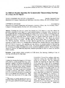
Figure 5: Visualizing the overdraw caused by different algorithms (according to the metric given in Section 4). From left to right (total number of view sample test-and-set operations in parenthesis): The scene, z-pass algorithm (19.7 million), z-fail algorithm (18.3 million), ours (1.2 million). The overdraw in the first two algorithms is proportional to the sum of the areas of projected shadow-quads, whereas in our algorithm view-samples that lie outside the triangle shadow-frustums are quickly culled.
ing them. The leaf nodes P Qwill now contain, for every view sample, log(1 − αi ) = log( 1 − αi ) for every triangle i that lies between it and the light source. To get the transmittance, for each view sample we simply raise e to the power of that value. This allows us to efficiently render shadows from models with per-triangle alpha values, which is often sufficient to generate compelling images (see Figure 1(c)). If the alpha-value needs to be interpolated over the triangle or fetched from a texture, we can not trivially accept an internal node in this simple way, as explained in the next paragraph. Colored transparent shadows are trivially supported by applying the above scheme to each wavelength (e.g. to a shadow buffer of RGB-tuples). Computing interpolated texture coordinates to support textured shadow casters is surprisingly simple in our method. Recall from section 3.1 that to determine whether a view sample is in shadow, we test its position against the four planes that make up the shadow frustum and evaluate the sign of the results. Though perhaps not immediately obvious, it can be shown that the distances obtained from each of the planes generated from the triangle edges (d0 , d1 , d2 ), are indeed a scaled version of the barycentric coordinates on the triangle. Scaling these distances such that d00 + d01 + d02 = 1, we have the true barycentric coordinates and can obtain the texture coordinates for the view sample. Moreover, this same approach holds in clip space, so no transformations are required. Given the texture coordinates, we can get the alpha-mask value, opacity value, or colored opacity value from a texture and proceed to update the shadow buffer for a view sample. Textured shadow casters
Note that while it is simple for us to introduce support for textured shadow casters, we are forced to abandon the trivial accept optimization described in section 3.1. It is simply not the case any more that if a tile lies entirely within the shadow volume of a triangle, all sub-tiles will have the same shadow value. Indeed, the triangle may cast no shadow if its texture is empty. Instead, when a tile is trivially accepted, we flag it as such and immediately traverse all sub-tiles without testing, until we reach the individual samples, for which we evaluate the texture and update the final level of the shadow buffer. This gives worse performance, of course, than when trivial accept is as simple as updating a shadow-buffer node, but still works at acceptable frame rates for complex models. There is a large drop in performance in our implementation, however, when the shadow of a single or very few triangles cover a large part of the screen. In this case, only one or a few multiprocessors will have any work to do and load-balancing becomes a problem. To alleviate this, we could instead employ the method described in [Abrash 2009] to trivially accept a tile. The tile and shadow frustum pair would then simply be pushed to a work queue that could be processed efficiently in a
separate pass. As noted previously, alpha-masked shadow casters are trivially supported by the shadow-mapping algorithm. When rendering the shadow map, a fragment can simply be discarded if the alpha value is below some threshold. Real valued alpha textures, however, are not easily supported, and one has to use more complex shadow-mapping techniques for this to work (e.g. Stochastic Transparency [Enderton et al. 2010]). Even when rendering alpha-masked shadow casters, the projection of a fragment onto the shadow map rarely covers a single texel, and so, filtering should be employed, and then the simple alpha-mask texture again returns a real valued result which will be thresholded. Our method trivially handles filtered lookups into an alpha-mask texture, and consequently, produces higher quality shadows (this too was noted by [Hasselgren and Akenine-Moller 2007]). Algorithm 2 Testing a shadow frustum against a tile. The algorithm first constructs the normalized device coordinate representation of the tile, and then tests the trivial-reject and trivial-accept corners against each of the four planes that define the shadow frustum. The xy extents of the tiles at a level, in normalized device coordinates, are available through the constant tileSize level . 1: procedure T EST T RI VOLUME(level , tile, tri ) 2: tileMin.xy ← (−1.0, −1.0) + tile ⊗ tileSize level 3: tileMin.z ← fetchMinDepth (level, tile) 4: tileMax.xy ← tileMin.xy + tileSize level 5: tileMax.z ← fetchMaxDepth (level, tile) 6: numInside ← 0 7: for each plane p i in tri do 8: if T EST P LANE A ABB(p i , tileMin, tileMax) > 0 then 9: return REJECT 10: else 11: numInside ← numInside + 1 12: if numInside = 4 then 13: return ACCEPT 14: else 15: return REFINE
When the shadow buffer contains a float per node instead of a single bit, the memory requirements are obviously much higher. Especially for high quality antialiased render targets (MSAA, CSAA or SSAA buffers) where every pixel has several depth samples, each of which should be tested against the shadow volumes for correct shadows, the memory footprint may be a limiting factor to the usefulness of our algorithm (or any other sample-accurate transparent shadows algorithm). For ex-
Stochastic transparent shadows
ample, a 1920x1080 buffer with 16 depth samples per pixel and 32bit float transmittance values would require 130MB of memory for the final level. Therefore, we suggest a different approach, where every pixel sample still holds a single bit of shadowing information. When updating the shadow buffer with a semi transparent shadow caster, the bit is simply set stochastically with a probability equal to α. The shadow buffer is used as per usual to decide whether each sample shall be considered lit or in shadow. When resolving the final pixel color the result will be noisy but correct on average (see Figure 6(a)). The proofs to why this works are equivalent to those in [Enderton et al. 2010], and, while we have not implemented it, the same scheme to stratify samples over a pixel as is presented in that paper should work well to reduce the noise. We have shown that semitransparent shadow casters present no problems to our algorithm. Since it is, like the original shadow-volume algorithm, essentially a deferred rendering algorithm, transparent shadow receivers are not quite as trivial, though. Since the light-visibility calculations do not (as with e.g. shadow maps) happen during fragment shading, but in a post-processing pass, simple techniques where polygons are sorted on depth before rendering will not work with our algorithm. Oftentimes, these approaches are not sufficient anyways, as they are prone to errors (two triangles may span the same depth and cannot be uniquely sorted). Our algorithm works well with depthpeeling [Everitt 2001], where layers of transparent objects are rendered in several passes and with Stochastic Transparency [Enderton et al. 2010], although the latter produces z-buffers with a high variance which causes a hierarchical z-buffer to be less than optimal. Transparent shadow receivers
samples to be tested are generated from the samples (x, y) positions in the pixel and the depth derivatives. The final shadow value used for the pixel will be the ratio of set bits to clear bits in the shadow buffer. Note that this is equivalent to projecting a fragment on a shadow map of infinite resolution and taking a number of PCF taps within this region.
3.4
Implementation
We have implemented our algorithm using CUDA, where the native SIMD group (called a warp) is 32 threads wide. One warp is issued per shadow frustum (with enough warps in each CUDA block to fully utilize the hardware), and the threads in each warp cooperate in rasterization of the frustum. The threads in a warp can efficiently exchange bit flags using the __ballot intrinsic (available on NVIDIA GPUs of compute capability 2.0 and above). On devices that lack this instruction, a parallel reduction in shared memory will yield the same result, at some cost in performance. Choosing a branching factor that matches the SIMD width allows the traversal to entirely avoid divergence (threads within a warp executing different code paths, for example if shadow frustums traverse the tree to different depths). A branching factor of 32 also matches the 32-bit word width, which makes updating bit masks simple and efficient. However, 32 items cannot tile a square region. To construct a tree from a square frame buffer, we instead alternate between 8 × 4 and 4 × 8 at each level. The implementation is otherwise faithful to the traversal algorithm (Algorithm 1) presented earlier. To accumulate results in the shadow-buffer hierarchy, we use atomic operations, e.g. the atomicOr intrinsic. While atomic operations are often held to be slow, we were not able to observe any penalty from using them, which may be because of the relatively low load the depth first traversal places on the memory subsystem. In order to support transparency, we need to use 32 floating point numbers per tile instead of 32 bits used for binary shadow. Updating these is done by using atomic add from each SIMD lane. To handle colored transparent shadows, we simply use three atomic adds, one per component.
(a)
(b)
Figure 6: Stochastic (a) and Real valued (b) transparent shadows.
3.3
Antialiasing
Hard shadow edges often mean that two neighboring pixels will have vastly different intensities, and so, anti-aliasing can greatly improve image quality. Our algorithm works well with full screen anti-aliasing schemes like MSAA, CSAA or SSAA as long as the pixel-sample positions’ can be obtained. For the shadow calculations, such a buffer is simply considered a large render target, and when the shadow buffer has to be updated for a view sample, the pixel sample positions offset is fetched from a table. We also suggest a novel anti-aliasing scheme that requires no extra depth-samples per pixel. When the scene is rendered from the camera, an additional color buffer is rendered that contains the x and y derivatives of the fragment’s depth. Building the depth buffer hierarchy works exactly as before, except the derivatives are used to find a minimum and a maximum depth already at the lowest level. The shadow buffer hierarchy is allocated with one additional level (so that a view sample will have a number of shadow bits instead of one single bit), and when traversing the shadow frustums through the hierarchical depth buffer, we simply traverse as though there were an additional level of the depth hierarchy, but the final view
3.5
Optimizations
As described in section 3.1, our shadow frustum vs. tile test is conservative, and can thus produce false positives leading to tiles refined unnecessarily. This problem is the 3D equivalent of the triangle-shadow problem for 2D rasterization (see Section 3.1), and causes traversal to refine tiles that are outside the projected shadow volume. To improve culling efficiency, we also test two additional edges that define the 2D projection of the shadow volume (illustrated using red lines in Figure 2). The new edges are defined in 2D homogeneous clip space, and are tested in a very similar fashion to the planes already used. Adding this test helps ensuring that we do not visit any tiles not actually within the on-screen shadow. Culling against shadow frustum silhouette
When rendering closed objects, we can choose to use only the triangles that face the light or the back-facing triangles as shadow casters [Zioma 2003]. This is also employed in shadow mapping, where rendering only back facing triangles can reduce self shadowing artifacts. For our algorithm, there is an even more compelling reason to use this approach. Consider what happens when a front-facing triangle that is visible from the camera is used as a shadow caster. This triangle will have to traverse the hierarchical depth buffer all the way down to the view samples that belong to that triangle, since all of these will lie exactly on the triangle plane. Unlike the traditional shadow-volume algorithm, using Front face culling
this optimization does not require that the model is actually modeled as a two manifold mesh. As long as the object will render correctly to screen with backface-culling, it will work robustly as a shadow caster with front-face culling. For example, unclosed backdrop geometry will cast shadows properly. We want to avoid computing light visibility for view samples that are already unlit, either because of the sample not facing the light, or being unlit for other reasons like being part of the background. To achieve this, we flag unlit view samples and do not include their depths when building the hierarchical depth buffers. Remove unlit depth samples
When traversing all shadow frustums through the hierarchical depth buffer, we set bits in the hierarchical shadow buffer representing completely shadowed tiles or view samples. Naturally, once a tile or view sample is found to be in shadow, given some triangle frustum, its state cannot change. Therefore an obvious optimization to our traversal algorithm is to stop traversal as soon as we reach a node that is already marked as being in shadow. It is simple to modify Algorithm 1 to AND the bitmask queue with the inverse of the current shadow buffer value for the node. This, however, will only stop the shadow frustum from being traversed through nodes that have previously been trivially accepted by some shadow frustum (not tiles that have been filled by several different shadow frustums), so the gain in efficiency is modest. Alternatively, a thread that fills a node can either recursively propagate that change up the hierarchy or simply update the one level above and rely on the changes to propagate due to other threads over time. Neither method improves performance in our implementation however, probably due to the increased cost of reading the shadow-buffer and the potentially long latency before an update is visible to other threads. An even more efficient optimization would be to keep the hierarchical depth buffer dynamically updated (by removing shadowed tiles from the hierarchy), but this seems less likely to be feasible.
and final merging) and omit any redundant buffer copies that happen when mixing OpenGL and CUDA. The timings presented for z-pass omit the time taken to evaluate how many shadow casters lie between the light and the camera. The graphs show the performance with and without the front-face culling (FFC) optimization described in section 3.5. The scene used is a part of the freely available Epic Citadel [Epic Games 2011] (∼ 60k triangles) which contains many open edges, in what are really closed objects, and so would not have worked with the simpler shadow-volume algorithms. The scene has been slightly modified to contain no onesided geometry (the cloth in the original model). All timings were measured on an NVIDIA GTX480 GPU.
Maintaining an updated shadow buffer
4
Results and Discussion
To evaluate the performance of our algorithm, we have implemented carefully tuned versions of the z-pass and z-fail algorithms. Our implementations are similar to those suggested by [Aldridge and Woods 2004], except they are implemented using shaders and run entirely on the GPU. Since the stencil buffer can only be incremented or decremented by one, shadow quads shared by two triangles are rasterized twice, as this is much faster than replacing the stencil buffer with a color buffer (which, using blending, can be incremented by two or more). In the z-fail implementation, we render the near and far caps, while in the z-pass we need only render the shadow quads. Both implementations rely on depth clamping to avoid clipping artifacts. In the z-pass algorithm, we initialize the stencil buffer with a value corresponding to the number of shadow volumes the camera is in. As mentioned, establishing this value robustly is still an unsolved problem and occasionally causes grave artifacts. Both z-pass and z-fail can also fail if the eight-bit stencil buffer overflows. The time taken to render the shadow volumes is plotted for a flythrough of a game-scene (see supplementary video), in Figure 7. We show results for two resolutions, 1024x1024 and 4096x4096. This latter resolution may seem extravagant, but really corresponds to approximately the same number of samples that would be processed for an image rendered in 1080p with 8xMSAA. The timings reported for our algorithm are those measured for generating the shadow buffer (build depth hierarchy, triangle-setup, rasterization
ZPASS ZFAIL New, with FFC New, no FFC
200 150 100 50 0 0
50
100
900 800 700 600 500 400 300 200 100 0 0
50
100
Figure 7: Comparing z-pass, z-fail and the new algorithm, with and without Front Face Culling (FFC), in a fly-through of the citadel scene. Above: Time taken (in ms) to generate per–viewsample shadow information. Below: Millions of test-and-set operations required. Left is for a render target of size 1024x1024, right 4096x4096. As can be seen from Figure 7, when front-face culling is enabled, our software GPU implementation outperforms z-fail even at the lower resolution, and performs with a similar average as z-pass at the higher resolution, though with much lower variability. Without front-face culling, z-pass is still faster than our algorithm at the higher resolution but, as noted previously, the z-pass algorithm is not entirely robust and so our algorithm is a compelling alternative. Moreover, for meshes without connectivity information or with short silhouette loops (e.g. destructible buildings, or a flock of birds) our frame times stay low while z-pass rendering times would increase significantly. To further examine the performance of our algorithm we have measured the total number of test-and-set operations per view sample. For the shadow-volume algorithms, we have ignored the work required by the rasterizer and early z-culling (as we lack information to properly evaluate that), and so the number of test-and-set operations reported is simply the total number of stencil updates required for a frame. For our algorithms, we have counted the total number of tile/shadow frustum and sample/shadow frustum tests performed. Figure 7 shows the number of test-and-set operations for the same scene and animation as before. Clearly, the new hierarchical algorithm is more efficient, even at relatively low resolutions, while at the high resolution it is especially effective. As expected, our
hierarchical approach scales well with increasing resolutions: raising the number of view samples sixteenfold only requires between about two to four times as many test-and-set operations, while for z-pass the increase is around 16 times. The results also demonstrate the low variability of the new algorithm which is due to our algorithms ability to trivially accept large tiles that lie within the shadow frustum and to trivially reject tiles that lie outside. Observe that, when front-face culling is disabled, the number of required test-and-set operations is more than doubled (roughly 2.2 times for the lower, and around 2.4 times for the higher resolution). This is the expected behavior, as visible front faces must be refined all the way to the sample level (see Section 3.5), and shows that front-face culling ought to be enabled whenever possible. Another important consideration for a shadowing algorithm is robustness and the artifacts it may produce. The z-pass algorithm is generally not robust, because of the camera in shadow problem, and because of stencil buffer overflow, which also affects the z-fail algorithm. When these failures are encountered, the shadow computed for the entire screen may be incorrect – a highly disturbing artifact. Our algorithm, on the other hand, has no inherent robustness issues, and will at worst produce light leakage if the mesh is not properly welded. The amount of memory required by our basic (non transparent) algorithm, is very low. For a 4096x4096 rendertarget our hierarchical shadow buffer requires only 2.1MB, besides the resident depth buffer, our hierarchical depth buffers require an additional 2.1MB for a total of 4.2MB. An eight-bit stencil buffer, which is a bare minimum for shadow-volume algorithms requires ∼ 16MB for the same resolution. The alias-free shadow-map implementation described in [Sintorn et al. 2008] stores all view sample positions (three floats) in a compact array of lists per light space pixel which would take ∼ 200MB at this resolution. Additionally, they require a shadow map where each texel needs to store as many bits as are the maximum list size. For a shadow map of 1024x1024 and a max list size of 512 that would mean an additional 16MB of memory. For comparison, a 4096x4096 omnidirectional shadow map would require 384MB. The results of the stochastic shadow buffer described in section 3.2 are demonstrated in Figure 6. The images are rendered at a resolution of 4096x4096 and downsampled to 1024x1024. Again, this is to illustrate how the algorithm could work with images rendered using high quality MSAA or CSAA. While it is quite noisy, the stochastic image renders slightly faster than using a float value per sample and, more importantly, requires only a single bit of visibility information per view sample. The memory footprint of our algorithm is thus reduced from the original ∼ 64MB in Figure 6(b), to only ∼ 2MB in Figure 6(a).
variants of our algorithm. The algorithm and the time taken to generate the shadows were (from left to right): standard binary visibility (7.9ms), semi-transparent shadow casters where all leafs have constant α = 0.5 (8.6ms), semi-transparent textured shadow casters (12.9ms), stochastic semi-transparent textured shadow casters (12.9ms), and colored semi transparent shadow casters (10.4ms). The choice of 32 as a branching factor for the hierarchical depth and shadow buffers is natural, as this matches both native word size and SIMD width. However, a high branching factor results in more wasted work; for example, all shadow frustums that are not culled in the setup phase will need to test all 32 tiles in the first level of the hierarchy, whereas a binary tree would only need to test two. Lower branching factor, on the other hand, results in deeper trees and more divergence. We have not explored this trade-off.
5
Future Work
The optimization where unlit samples are removed enables the use of a two-pass approach, where a first pass runs the algorithm only on those triangles that are expected to be good blockers by some heuristic, then refreshes the hierarchy by removing yet more unlit samples, and finally traverses the remaining triangles [Olsson and Assarsson 2011]. As constructing the depth hierarchy is cheap, this optimization may yield a significant increase in efficiency, especially if blocker geometry (i.e. conservative simple geometry) is placed manually or generated. The algorithm could be extended to handle soft shadows quite simply, in a manner similar to that of [Sintorn et al. 2008]. The triangle frustums would then be expanded to include the whole influence region of the triangle, given an area light source, and the shadow buffer could contain, for each view sample, a bit per light sample. Also, our novel antialiasing scheme resembles PCF filtering in many ways. It seems likely that this algorithm could be modified to support samples taken outside the pixels’ bounding box, to support PCF style blurred shadows in our algorithm. Several problems remain to be solved in these areas, though.
6
Conclusion
We have presented a novel shadow algorithm based on individual triangle shadow volumes, which combines many of the strengths of shadow maps and shadow volumes. We also demonstrated a GPU software implementation of a hierarchical rasterizer that supports the algorithm. Despite running entirely in software, it competes well against highly tuned implementations of shadow volumes which rely heavily on hardware acceleration, and offers realtime performance. Meanwhile, the new algorithm is completely robust, works for any aribtrary collection of triangles and integrates easily into a deferred rendering pipeline making it a compelling choice for rendering pixel accurate shadows, especially at high resolutions.
References A BRASH , M. 2009. Rasterization on larrabee. Dr. Dobbs Journal. ¨ A ILA , T., AND A KENINE -M OLLER , T. 2004. A hierarchical shadow volume algorithm. In Proc. of the ACM SIGGRAPH/EUROGRAPHICS conf. on Graphics hardware, HWWS ’04, 15–23. Figure 8: The results of rendering a scene with different variants of our algorithm. Figure 8 shows the tree from figure 1(b) rendered with different
A ILA , T., AND L AINE , S. 2004. Alias-free shadow maps. In Proc. of EGSR 2004, 161–166. A LDRIDGE , G., AND W OODS , E. 2004. Robust, geometryindependent shadow volumes. In Proc. of 2nd international conf.
on Computer graphics and interactive techniques in Australasia and South East Asia, GRAPHITE ’04, 250–253. A NNEN , T., M ERTENS , T., S EIDEL , H.-P., F LERACKERS , E., AND K AUTZ , J. 2008. Exponential shadow maps. In Proc. of graphics interface 2008, GI ’08, 155–161.
K IM , B., K IM , K., AND T URK , G. 2008. A shadow-volume algorithm for opaque and transparent nonmanifold casters. journal of graphics, gpu, and game tools 13, 3, 1–14. L AINE , S. 2005. Split-plane shadow volumes. In Proc. of Graphics Hardware 2005, 23–32.
A RVO , J. 2004. Tiled shadow maps. In Proc. of Computer Graphics International 2004, 240–246.
L AURITZEN , A., S ALVI , M., AND L EFOHN , A. 2011. Sample distribution shadow maps. In Proc., I3D ’11, 97–102.
B ILODEAU , W., AND S ONGY, M., 1999. Real time shadows. Creativity 1999, Creative Labs Inc. Sponsored game developer conferences, Los Angeles, California, and Surrey, England.
L EFOHN , A. E., S ENGUPTA , S., AND OWENS , J. D. 2007. Resolution matched shadow maps. ACM TOG 26, 4, 20:1–20:17.
C ARMACK , J., 2000. Z-fail shadow volumes. Internet Forum. C ARPENTER , L. 1984. The a -buffer, an antialiased hidden surface method. SIGGRAPH Comput. Graph. 18 (January), 103–108. C HAN , E., AND D URAND , F. 2004. An efficient hybrid shadow rendering algorithm. In Proc. of the EGSR, 185–195. C ROW, F. C. 1977. Shadow algorithms for computer graphics. SIGGRAPH Comput. Graph. 11 (July), 242–248.
L LOYD , B., W END , J., G OVINDARAJU , N. K., AND M ANOCHA , D. 2004. Cc shadow volumes. In EGSR/Eurographics Workshop on Rendering Techniques, 197–206. L LOYD , D. B., G OVINDARAJU , N. K., Q UAMMEN , C., M OL NAR , S. E., AND M ANOCHA , D. 2008. Logarithmic perspective shadow maps. ACM TOG 27 (November), 106:1–106:32. L OKOVIC , T., AND V EACH , E. 2000. Deep shadow maps. In Proc. SIGGRAPH 2000 (Aug.), SIGGRAPH 2000, 385–392.
D ONNELLY, W., AND L AURITZEN , A. 2006. Variance shadow maps. In Proc. of i3D 2006, I3D ’06, 161–165.
M C C ORMACK , J., AND M C NAMARA , R. 2000. Tiled polygon traversal using half-plane edge functions. In Proc. of ACM workshop on Graphics hardware, HWWS ’00, 15–21.
E ISEMANN , E., A SSARSSON , U., S CHWARZ , M., AND W IMMER , M. 2009. Casting shadows in real time. In ACM SIGGRAPH Asia 2009 Courses, SIGGRAPH Asia 2009.
M C G UIRE , M., AND E NDERTON , E. 2011. Colored stochastic shadow maps. In Proc. of i3D’11 (Februari.).
E NDERTON , E., S INTORN , E., S HIRLEY, P., AND L UEBKE , D. 2010. Stochastic transparency. IEEE TVCG 99.
O LANO , M., AND G REER , T. 1997. Triangle scan conversion using 2d homogeneous coordinates. In Proc. of ACM workshop on Graphics hardware, 89–95.
E PIC G AMES, 2011. Unreal development kit: Epic citadel. http: //www.udk.com/showcase-epic-citadel. E VERITT, C., AND K ILGARD , M. J., 2002. Practical and robust stenciled shadow volumes for hardware-accelerated rendering. Published online at http://developer.nvidia.com. E VERITT, C., 2001. Interactive order-independent transparency. Published online at http://www.nvidia.com/object/ Interactive_Order_Transparency.html. F ERNANDO , R. 2005. Percentage-closer soft shadows. In ACM SIGGRAPH 2005 Sketches, SIGGRAPH 2005. F OREST, V., BARTHE , L., G UENNEBAUD , G., AND PAULIN , M. 2009. Soft textured shadow volume. Computer Graphics Forum, EGSR 2009 28, 4, 1111–1121. F UCHS , H., G OLDFEATHER , J., H ULTQUIST, J. P., S PACH , S., AUSTIN , J. D., B ROOKS , J R ., F. P., E YLES , J. G., AND P OUL TON , J. 1985. Fast spheres, shadows, textures, transparencies, and image enhancements in pixel-planes. SIGGRAPH Comput. Graph. 19 (July), 111–120. H ASSELGREN , J., AND A KENINE -M OLLER , T. 2007. Textured shadow volumes. Journal of Graphics Tools, 59–72. H EIDMANN , T. 1991. Real shadows, real time. Iris Universe 18, 28–31. Silicon Graphics, Inc.
O LSSON , O., AND A SSARSSON , U. 2011. Improved ray hierarchy alias free shadows. Technical Report 2011:09, Chalmers University of Technology, may. R EEVES , W. T., S ALESIN , D. H., AND C OOK , R. L. 1987. Rendering antialiased shadows with depth maps. In Proc., SIGGRAPH 87, 283–291. S INTORN , E., AND A SSARSSON , U. 2009. Hair self shadowing and transparency depth ordering using occupancy maps. In Proc., i3D ’09, 67–74. S INTORN , E., E ISEMANN , E., AND A SSARSSON , U. 2008. Sample-based visibility for soft shadows using alias-free shadow maps. CG Forum (EGSR 2008) 27, 4 (June), 1285–1292. S TAMMINGER , M., AND D RETTAKIS , G. 2002. Perspective shadow maps. In Proc., SIGGRAPH 2002, 557–562. W ILLIAMS , L. 1978. Casting curved shadows on curved surfaces. SIGGRAPH Comput. Graph. 12 (August), 270–274. W IMMER , M., S CHERZER , D., AND P URGATHOFER , W. 2004. Light space perspective shadow maps. In Rendering Techniques 2004 (Proc. EGSR), 143–151. Y UKSEL , C., AND K EYSER , J. 2008. Deep opacity maps. Computer Graphics Forum (Proc. of EUROGRAPHICS 2008) 27, 2.
H ORNUS , S., H OBEROCK , J., L EFEBVRE , S., AND H ART, J. C. 2005. ZP+: correct Z-pass stencil shadows. In ACM symp. on Inter. 3D Graphics and Games, I3D, April, 2005, 195–202.
Z HANG , F., S UN , H., X U , L., AND L UN , L. K. 2006. Parallelsplit shadow maps for large-scale virtual environments. In Proc. of the 2006 ACM international conf. on Virtual reality continuum and its applications, VRCIA ’06, 311–318.
J OHNSON , G. S., L EE , J., B URNS , C. A., AND M ARK , W. R. 2005. The irregular z-buffer: Hardware acceleration for irregular data structures. ACM Trans. on Graphics 24, 4, 1462–1482.
Z IOMA , R. 2003. Reverse extruded shadow volumes. In ShaderX2 : Shader Programming Tips & Tricks with DirectX 9, W. Engel, Ed. Wordware Publishing, 587–593.
K IM , T.-Y., AND N EUMANN , U. 2001. Opacity shadow maps. In Proc. EG Workshop on Rendering Techniques, 177–182.