Efficient Shadow Computations in Ray Tracing Andrew Woo Alias Research
Two simple techniques speed up shadows in ray tracing. Both require little memory and easily extend to other ray types. One can also benefit radiosity-related computations.
ay tracing1 is the most common technique used to implement mirror reflections and refractions. Because of its simplicity and flexibility, graphicists also use ray tracing to produce elaborate-looking shadows. However, ray-traced shadows can be computationally expensive and might turn out to be the most significant part of the total rendering time. We can compute ray-traced shadows for simple lights by shooting a ray from the point to be shaded to each light source. If we assume the tessellated polygon to be the main primitive of concern, then we can perform ray-polygon intersections along the ray to determine the shadowing occlusion— that is, whether or not the point to be shaded lies in shadow. In this article we will examine two techniques to speed up shadow computations in ray tracing. The first, atomic adaptive sampling, is intended for any light type (directional, spot, point, linear, and area lights) in antialiasing, while the second, plane vertex checking, specifically accelerates shadow computation of linear and area lights. We can extend the basic ideas to other ray types, and for the plane-vertex check, to radiosity applications as well. Existing surveys explain the fundamentals and provide references to intersection culler and shadow algorithms.2
R
Atomic adaptive sampling Adaptive sampling1 is a common antialiasing technique for ray tracing. For each pixel, this technique takes a minimum set of point samples at the corners (and perhaps in the middle) of the pixel. If the RGB values (representing the sample's shading accumulation of all its cast, reflection, refraction, and shadow rays) differ by some threshold value, then we divide the pixel into quadrants and point
sample at the corners of those quadrants. For each quadrant, if the RGB values differ, then we recursively sample further subquadrants until the RGB values are fairly equal within some threshold value or until we reach the maximum recursive level. Any samples done above the minimum sampling rate are considered subpixel samples. See Figure 1, where the largest circles indicate the initial four corner samples of a pixel. The smaller circles indicate subpixel samples, needed because of the presence of a polygon. The smaller the circle, the deeper in the adaptive recursion it is. For each additional subpixel point sample required, we need to shoot a new ray and do the computations for the cast-ray (the first-generation rays shot from the eye) information, reflection, refraction, and shadows all over again. This can be very expensive. But do we really need to recompute all this information? We attempt to accelerate only the shadow computations for the cast rays. These computations make up the most significant part of the total shadow rendering expense. We keep two arrays, each of size l(X+1), where X is the X resolution of the rendered image and l represents the total number of lights. Each array element contains bits of occlusion information: Inshadow, Not_Inshadow, or Complex_Shadow. It also contains a pointer to the surface hit by the cast ray. In this context, the surface is not tessellated polygons but the actual surface (in our case, a nonuniform rational B-spline surface). The polygon versus surface differentiation is a necessary distinction throughout this article, since the chances of hitting the same surface are much higher than those of hitting the same tessellated polygon. For each corner sample (and for each light), if the cast ray's shadow occlusion has the point in shadow (umbra), then we mark the
IEEE Computer Graphics & Applications
Figure 1. Adaptive Sampling.
array element with Inshadow. If the point is not in shadow, we mark it with Not_Inshadow. If shadows were computed from transparent surfaces or from a penumbra region, then we mark the array element with Complex_Shadow. We need two arrays to hold the top and bottom boundaries making up the row of pixels' corner samples, and we flip the two arrays for each new scan line of pixels (for shared sampling information at the scanline boundaries). If we need to subpixel sample, then we continue to shoot rays as usual. However, for each subpixel's cast-ray shadow computation, we check the corner samples' shadow indicators from the two arrays. For each light, if the shadow indicators at the corners of the current pixel are all Inshadow and the cast ray hits the same surface, then we can assume, without shooting a shadow ray, that this new subpixel point is in shadow for the current light. The same goes for Not_Inshadow, where we can assume the subpixel point is not in shadow. The only time we need to shoot a shadow ray is when we encounter Complex_Shadow or when the corner samples' shadow indicators are not all equal. Note that we repeat this process for each light. This method provides a big advantage by reducing the number of shadow rays shot. For most subpixel samples, additional sampling usually results because of highlight aliasing, noisy textures, mirror reflections, refractions, spotlight boundaries, or encountering just one light's shadow boundary. Note that this acceleration is an adaptive sampling scheme with respect to shadow occlusion indicators, similar to an idea proposed before.3 However, we apply it to shadows to help speed up antialiasing with negligible or no sacrifice in image quality compared to standard adaptive sampling. Other uses of atomic adaptive sampling We can take advantage of this ray-shooting reduction for other ray types as well. For example, for cast rays, if the same polygon is hit at the corner samples, then we can assume the same happens for the subpixel samples. We just intersect the cast ray with that polygon and continue with the rest of the ray tracing process. So we avoid any culling preprocessing and all other cast ray-polygon intersection tests, unless the ray does not intersect the polygon at all. Then we have to go through the entire cast ray procedure, but this should be rare (it should never occur if the polygon is convex). And we can store all of this information in two l(X+1)-sized arrays; as in the shadow acceleration case. For the corner samples with reflection rays, we can store an RGB shading accumulation value R that represents the shading at the reflection ray and all the descendent rays below the reflection ray. If, when determining reflection, the corner samples register similar R values and the same surface hit by the parent ray, then the subpixel sample can assume that a bilinear interpolation of the corner R values is a good approximation to the current reflection ray (and its descendents), without shooting further reflection or descendent rays. We can apply the same idea to refraction as well. Note that for each sample we can view the ray tracing (recursive) process as a ray tree,1 where each cast, reflection, and refraction ray represents a node in the tree. Then the suggestions in this section
basically constitute adaptive sampling for each component in the ray tree— hence the name atomic adaptive sampling. This optimization can provide great savings, since for most cases only a small component of the entire ray tree needs further sampling in order to antialias. Unfortunately, since memory is the main constraint on the Macintosh platform, all our optimizations consider only the top levels of the ray tree as an acceptable compromise; that is, only the top-level 2-bit shadow occlusion, reflection, refraction, and cast-ray information is stored. With more available memory, it is worthwhile to apply the same trick throughout the entire ray tree. We can do this by allocating the maximum size of a ray tree (assuming fixed reflection and refraction limits), in the form of a stack array, to each element in the l(X+1) arrays. This form of adaptive sampling is also very flexible. It does not inhibit additional criteria in performing additional or reduced sampling. For example, we might want to compare surface normals at the subpixels (at each component of the ray tree). If the difference in surface normal changes too drastically, we probably would want to shoot additional reflection, refraction, or shadow rays even if the corner samples' RGB values are similar. We also want to force additional sampling if the shared boundary subpixel samples— if sampled previously— show drastic RGB changes compared to the corner samples. These can improve the antialiasing quality on top of adaptive sampling, as we might detect drastic changes. There is also no stopping the use of the many ideas from path tracing,4 where we can avoid certain rays that contribute little to the final pixel value. Plane-vertex checking for linear and area lights Several methods, most covered in a survey article,2 compute shadows from linear lights. The most widely used method is quite brute-force, and very expensive. For any linear light, we shoot K stochastic and independent shadow rays to points on the light.5-7 The final shadow occlusion is some weighted average of those K shadow rays, resulting in soft shadows (penumbra). For each shadow ray, we can use our favorite intersection culler to improve ray tracing performance. The culler I use currently is a spatial subdivision scheme using voxel traversal.8 Thus the pseudocode in Figure 2 performs brute-force linear-light shadow occlusion (assuming equal weighting, for simplicity's sake).
IEEE Computer Graphics & Applications
Figure 2. Pseudocode for brtueforce linear light shadow occlusion.
occlusion = 0.0; for (i = 0; i < K; i++) { getShadowRay (S, light, &shadowRay[i], &voxel); /* traverse voxels, and go through each voxel's polygon list */ for (nextVoxelTraversed(shadowRay[i], &voxel)) { for (obj = voxel->objList; obj != NULL; obj = obj->next) { if (obj->rayiD == currRayID) continue; obj->rayID = currRaylD; if (intersectRay (shadowRay[i], obj)) { occlusion++; goto NEXTRAY; } } } NEXTRAY: currRaylD++;
Figure 3. Plane-vertex check For linear lights
} occlusion /= K;
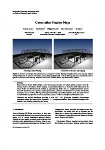
We use the rayID9 to eliminate multiple ray-polygon intersections with the same ray of the same polygon. This is necessary because the neighboring voxels traversed might contain references to the same polygon. A global currRayID is incremented by 1 for every new ray shot. Each polygon contains its own rayID, updated to currRayID if a ray-polygon intersection test is done against that ray. Thus, we only need to compare the polygon's rayID with currRayID to determine if this polygon has been tested for intersection against that particular ray. In this section I propose a shadow determination optimization for linear lights. Its success depends on the assumption that many of the same candidate polygons, lying in the same voxels traversed, need to test intersection against the K shadow rays. This optimization can be especially effective for tessellated polygons, where each surface's polygons bunch closely together. For each point S to be shaded, we assume that K shadow rays are shot to determine occlusion. We continue to voxel traverse as before, but with an additional check. With S and the boundary points of the linear light L1 and L2, we can form a plane equation (those points actually form a light triangle); see Figure 3. Let the plane equation be of the form Ax + By + Cz = d, where N = (A, B, C) is the plane normal as defined by (S - LI ) x (S - L2) and d = N x S. We can easily check whether a polygon crosses this plane equation by inserting the polygon vertices (xi, yi, zi) into the plane equation. If Axi + Byi + Czi < d for all vertices, or Axi + Byi + Czi > d for all vertices, then that polygon can not possibly intersect the plane equation and thus cannot occlude S. (We can replace this check by the bounding box vertices for more complex surfaces than the polygon.) We refer to this check as the plane-vertex check. For a point S to be shaded, let currRayID for the first of the shadow rays be m. Then all K shadow rays to compute S's occlusion have rayID = [m, m+K-1]. We only want to do the plane-vertex check once per polygon for each point S, on the fly, as we encounter them during voxel traversal. Thus if the polygon's rayID < m (this indicates that the polygon is encountered for the first time for point S), then we perform the plane-vertex check before any ray-polygon intersection tests. If the polygon cannot possibly intersect the plane equation, then we set the polygon's rayID to m+K-1, to indicate that the polygon cannot occlude S for the duration of the K shadow rays. We guarantee this by checking if currRayID = polygon rayID.
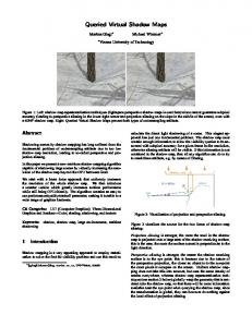
The = = (equality) check covers the case of avoiding multiple ray-polygon intersection tests with the same ray (as used before). We use the < check to cull polygons that do not cross the plane equation. Thus, the integer comparison can trivially reject many polygons from ray-polygon intersection tests with no extra memory or data structures required. Figure 4 contains pseudocode to clarify the workings of the optimization. Note that we can consider this optimization a point-sampling variation of beam tracing.10 The plane-vertex check has the coherence information of beam tracing while maintaining the ease of simply ray tracing a discrete sample. Extension to area lights We can apply the plane-vertex check and extended rayID to shadows from area lights as well. Let us assume that K stochastic shadow rays are to be shot to an area light described by E edges. From point S to be shaded, we can form a light pyramid with the edges of the area light. See Figure 5, where E = 4. For the plane-vertex check, we do exactly the same as in the linear light case, except we compute E plane equations. Each plane with normal Ni is derived from S and an edge of the light, as in Figure 5.
IEEE Computer Graphics & Applications
occlusion = 0.0; m = currRayID; getPlaneEquation (S, light, &A, &B, &C, &d); for (i = 0; i < K; i++) { getShadowRay (S, light, &shadowRay[i], &voxel);
Figure 4. Pseudocode to clarify the optimization.
/* traverse voxels, and go through each voxel's polygon list */ for (nextVoxelTraversed (shadowRay[i], &voxel)) { for (obj = voxel->objList; obj != NULL; obj = obj->next) { /* new culling step */ if (obj->raylD >= currRayID) continue; /* doing plane-vertex check */ if (obj->raylD < m && i != K - 1) { if (!crossPlaneEquation (A, B, C, d, obj)) { /* not cross plane, avoid intersections */ obj->raylD = m + K - 1; continue; } } /* ray-polygon intersection tests */ obj->raylD = currRayID; if (intersectRay (shadowRay[i], obj)) { occlusion++; goto NEXTRAY; } } } NEXTRAY: currRaylD++; occlusion /= K; Figure 5. Plane-vertex check for area lights.
The polygon's rayID is assigned m+K-1 only if the polygon lies completely outside the pyramidal region— this discards the polygon from any ray-polygon intersection tests. Assuming a counter-clockwise description of the area light, a polygon completely outside the pyramidal region means that all the polygon's vertices (xi, yi, zi) satisfy just one of the E plane equations where Ajxi + Bjyi+Cizi > dj, j = [1, E] and Nj = (Aj, Bj,Cj). This, however, assumes that the light must be convex.
Other uses of planevertex checking We can perform the plane-vertex check for cast rays when we assume that exactly one ray is cast per pixel— that is, when there is no antialiasing. Then we can form the plane equation against the horizontal row of these pixels and the eye origin (the plane equation has d = 0 if we ray trace in eye-space coordinates). We also allocate a temporary array the size of the X resolution of the rendered image. With K = X, we perform all the cast ray computations as a first pass, traversing voxels and applying the rayID optimization from the plane-vertex check. We store the first pass information in the O(X) temporary array with contents of the hit point, cast-ray vector, and surface hit. Then as a second pass, we continue on with the shadow, reflection, and refraction computations with the cast-ray information already computed. For cast rays during antialiasing, if we know K ahead of time, then we can form two plane equations that encompass the horizontal row of pixels and perform two plane-vertex checks to determine if a polygon lies inside the two planes. For example, if we want to use some form of stratified sampling,11 specifically N-rooks sampling (as used by Shirley in his implementation12), then we know that K = NX and can easily perform this optimization. However, adaptive sampling cannot compute all cast rays as a first pass ahead of time. We can only apply this optimization to corner samples that represent the minimum sampling rate before invoking its adaptive nature of antialiasing (but those cases are subpixel samples, which should mostly have been optimized by atomic adaptive sampling already). This minimum sampling rate is fixed, thus K = X+1. If we use jitter5 with adaptive sampling, we need to expand the plane boundaries to encompass the maximum jitter factor. We can also extend the plane-vertex check for fuzzy reflections and refractions, implemented in the manner suggested by Cook et al.,5 where a bundle of rays are shot from the same origin to generate such effects. Similarly, in some radiosity environments12,13 ray tracing is used to more accurately compute the inter-reflections of light. In progressive refinement techniques, bundles of rays are shot from polygons in particular directions to determine which
IEEE Computer Graphics & Applications
Figure 6. Test image of pots and a chair.
Figure 7. Test image of a desk.
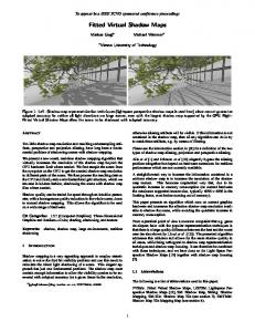
polygons receive the radiant power associated with the bundle. Iterations through this process result in a rendering that accounts for inter-reflections of light. Using the plane-vertex check with respect to each bundle of rays, many polygons can be trivially rejected as candidates to receive this radiant power. Testing and results I did testing on a Macintosh Quadra 950. All test images (Figures 6 through 9) were rendered at 640 x 480 pixels at 72 dots per inch, with a maximum adaptive sampling recursion level of 3 (Figure 6 shows a maximum level of 3). This permits a maximum of 25 samples per pixel. I also set mirror reflections to a maximum level of 3. Each surface is mirror reflective. I implemented the optimizations mentioned here in a Macintosh 3D package named Sketch!, version 1.5. Note that all curved surfaces are modeled and represented in nonuniform rational B-spline form and tessellated into triangles for rendering. For atomic adaptive sampling, we can easily improve the total rendering time by 20 to 40 percent, where percent is measured by [old_time - new_time] / old_time. Note that the subpixel sampling for cast rays has thus been optimized by applying atomic adaptive sampling. Corner samples are optimized by the plane-vertex check, accounting for only about 5 percent improvement due to the already efficient voxel culler implemented.8 As scenes get more complex, with noisy textures, more geometry, or increasing numbers of lights, more savings can be had. Some benchmarks appear in Table 1.
("Alias Time" indicates the time to render an aliased image; "AS Time" and "AAS Time" indicate the time to render an anti-aliased image using the standard adaptive sampling technique and atomic adaptive sampling, respectively.) Another note: For most complex antialiased images, ray tracing takes about two to five times longer than it does for aliased images (1 point sample per pixel), assuming a maximum recursive adaptive level of 3. This extreme slowness results from the usually significant number of samples necessary once the current pixel needs antialiasing. With the atomic adaptive sampling scheme, we can easily keep that expense to about twice the time of computing an aliased image. Unfortunately, Sketch! does not support linear and area lights, hindering the testing of the plane-vertex check of such lights. However, I implemented an efficient kludge that faked soft shadows from point lights. I placed a two-unit long line on the point light P, where L1 = P, L2 = P + 2Ns, and Ns = surface normal of S. I initially shot one shadow ray from S to P. If S was not in shadow, then I considered it fully lit. If S was in shadow, then I shot K shadow rays to this two-unit long line (to get soft shadows). In the tori image (Figure 9), l = 1, K = 8, and about 8.5 percent overall time speedup was accounted for by the plane-vertex check, with 1,369,790 ray-triangle intersection tests avoided.
Table 1. Rendering times. Example
No. of Lights
AS Time
AAS Time
Percent Improvement
Alias Time
Pots & Chair (Figure 6)
2
66.5 minutes
47.5 minutes
40%
19 minutes
Desk (Figure 7)
1
28 minutes
22 minutes
22%
14 minutes
Spheres (Figure 8)
3
45 minutes
25 minutes
44%
16 minutes
IEEE Computer Graphics & Applications
Figure 9. Test image of a tori.
Figure 8. Test image of spheres.
3. T. Akimoto, K. Mase, and Y. Suenaga, "Pixel-Selected Ray Tracing," IEEE CG&A, Vol. 11, No. 4, July 1991, pp. 14-22. 4. J. Kajiya, "The Rendering Equation," Computer Graphics (Proc. Siggraph), Vol. 20, No. 4, Aug. 1986, pp. 143-150. 5. R. Cook, T. Porter, and L. Carpenter, "Distributed Ray Tracing," Computer Graphics (Proc. Siggraph), Vol. 18, No. 3, July 1984, p.109-115.
I also implemented an adaptive variation to the above linear light kludge, in place of the constant K shadow rays. I shot shadow rays at the corners of the light and— if they differed in occlusion— subdivided, shot shadow rays, and tested again. The minimum sampling rate was set at 3 (that is, 21 + 1) and the maximum at 17 (24 + 1). Thus I set K = 17 and reinitialized currRayID to m+17 after evaluating the linear light occlusion, regardless of how many shadow rays were actually shot. With the same tori image (Figure 9), I got only about a 2 percent speedup because, in my test case, the majority of the sampling requires only the minimum three samples (mostly umbra sections). Thus, fewer savings were passed on. Conclusions and future work In this article I proposed two simple acceleration techniques to significantly speed up shadows and other aspects of ray tracing. Both techniques require little (an extra 50 to 100K) memory and no preprocessing. In addition, applications such as radiosity-related computations can benefit from the plane-vertex optimization. Both techniques also break away from traditional ray tracing acceleration approaches, in which each ray is independently culled. Such approaches can only accelerate so much. My techniques can achieve very good acceleration taking into account a related group of rays, while not complicating the flow of the standard ray tracing process too much. We need additional techniques to exploit such ray relations, as well as to reduce severe memory swapping during ray tracing. Such techniques can further improve ray tracing performance. Acknowledgments Thanks must go to Andrew Pearce (Alias Research), Pierre Poulin (University of British Columbia), Eric Haines (3D/Eye), Kelvin Sung (National University of Singapore), and the CG&A reviewers for their suggestions and comments. References 1. T. Whitted, "An Improved Illumination Model for Shaded Display," Comm. ACM, Vol. 23, No. 6, June 1980, pp. 343-349.
6. P. Poulin and J. Amanatides, "Shading and Shadowing with Linear Light Sources," Proc. Eurographics, Elsevier, North Holland, 1990, pp. 377-386. 7. K. Picott, "Extensions of the Linear and Area Lighting, Models," IEEE CG&A, Vol. 12, No. 2, March 1992, pp. 31-38. 8. A. Woo, "Ray Tracing Polygons Using Spatial Subdivision," Graphics Interface, Canadian Information Processing Society, Toronto, May 1992, pp. 184-191. 9. J. Amanatides and A. Woo, "A Fast Voxel Traversal Algorithm for Ray Tracing," Proc. Eurographics, Elsevier, North Holland, Aug. 1987, pp. 1-10. 10.P. Heckbert and P. Hanrahan, "Beam Tracing Polygonal Objects," Computer Graphics (Proc. Siggraph), Vol. 18, No. 3, July 1984, pp. 119-127. 11.M. Lee, R. Redner, and S. Uselton, "Statistically Optimized Sampling for Distributed Ray Tracing," Computer Graphics (Proc. Siggraph), Vol. 19, No. 3, July 1985, pp. 61-67. 12.P. Shirley, "A Ray Tracing Method for Illumination Calculations in Diffuse-Specular Scenes," Graphics Interface, Canadian Information Processing Society, Toronto, June 1990, pp. 205-212. 13.E. Haines and J. Wallace, "Shaft Culling for Efficient Ray-Traced Radiosity," Eurographics Workshop on Rendering, E. Jansen, ed., Springer-Verlang, Berlin, May 1991, pp. 13-25. Andrew Woo is currently a senior software engineer at Alias Research, working on Sketch!, a Macintosh 3D product. He previously worked on the NeoVisuals project at SAS Institute. Woo received a BS in 1987 for computer science and commerce, and an MS in 1989 for computer science, both at the University of Toronto. His interests lie in general rendering issues, especially acceleration and parallelization techniques, and illumination models. Woo is a member of IEEE and ACM, and served as treasurer for the Toronto Local Siggraph Group from 1989-1992. Readers can contact Woo at Alias Research, 110 Richmond Street East, Toronto, Ontario, Canada, MSC IPI; e-mail
[email protected].
2. A. Woo, P. Poulin, and A. Fournier, "A Survey of Shadow Algorithms," IEEE CG&A, Vol. 10, No. 6, Nov. 1990, pp. 13-32.
IEEE Computer Graphics & Applications