We notice that the number of maximum operations does not depend on the value of k (odd). We will focus on dilation but the erosion case can be processed ...
An efficient hardware architecture without line memories for morphological image processing Christophe Clienti, Michel Bilodeau and Serge Beucher MINES Paristech CMM - Centre de morphologie mathmatique, Mathmatiques et Syst`emes 35 rue Saint Honor´e - 77305 Fontainebleau cedex, France.
Abstract. In this paper, we present a novel hardware architecture to achieve erosion and dilation with a large structuring element. We are proposing a modification of HGW algorithm with a block mirroring scheme to ease the propagation and memory access and to minimize memory consumption. It allows to suppress the needs for backward scanning and gives the possibility for hardware architecture to process very large lines with a low latency. It compares well with the Lemonnier’s architecture in terms of ASIC gates area and shows the interest of our solution by dividing the circuit area by an average of 10.
1
Introduction
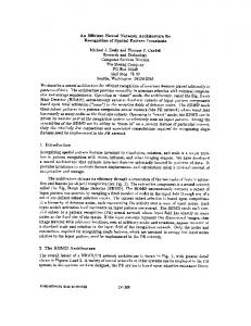
For more than 40 years, the use of Mathematical Morphology for image processing has been constantly growing in many domains such as medical imaging, computer vision multimedia application or security [1]. Real-time image processing with large images and big kernels or structuring elements could be very time-consuming. A possibility to reduce the computational power required by architectures is to use the well-known kernel decomposition. For example, if we consider an erosion with a N × N structuring element, the complexity in terms of min operations to find the minimum in a kernel will be O(N 2 ). Now, if we apply N/2 times a 3 × 3 structuring element, the complexity will be O(N ) to get the same result. When using simple structuring elements such as rectangles, rhombuses or octagons, the decomposition will be done by using a segment structuring element successively applied on images with a neighborhood operation (an erosion for instance). Figure 1 shows an example of a decomposition using three segments to produce an hexagon, a pixels access for 2D or 3D images must be done using the Bresenham coordinate generation [2]. This type of decomposition used with recursive implementation of erosions or dilations allows to approximate many types of 2D structuring elements [3]. Applications are numerous and we can cite an algorithm using segment structuring elements to estimate the skew angle of scanned documents [4]. The Interest of segment structuring elements no longer needs to be proved, so it could be useful to design fast morphological operators to take advantage of
Fig. 1. Structuring element composition example
decompositions. The first part of the paper is dedicated to existing algorithms designed to work with segment structuring elements, the second part shows our modifications to reduce memory requirements and latency, the third part presents our architecture and a comparison in terms of memory consumption is made between our dedicated architecture and the existing ones.
2
Existing algorithms description
Two main recursive algorithms exist to compute erosion or dilation along the discrete lines of an image with centered segment structuring elements. Both use pixels min/max propagations in a forward and backward way. These algorithms are often described in the literature and only a brief description will be made here. In both approaches we consider an image line f of size M , with an orientation θ and a centered segment structuring element of size k. 2.1
Lemonnier’s Algorithm
This algorithm described in [5] works for dilation only, but erosion could be achieved using the duality property between erosion and dilation. Two scans are needed to process one line. Firstly, a recursive forward scan on f is performed considering maxima propagation every k pixels to produce the line h. Secondly, a recursive backward scan on h is made to spread maxima in the other direction to get a centered structuring element. The Lemonnier’s algorithm is interesting because only two max operators are used for processing each pixel, but the high number of if statements must be taken into account and an implementation on SIMD processors would not be well-suited. Lemonnier’s algorithm could be mapped to data flow dedicated architectures as described in figure 2. Both passes of the algorithm are synthesized in two pipeline stages with two line memories in between. The latter are needed to store first stage pixels of line hn in a forward way in the first memory, and at the same time to read pixels of line hn−1 of the second line memory in a backward way by the second stage. When the processes terminate on each stage, line memories are swapped to store the result of line hn+1 of the first stage and to read line hn by the second stage. However, the double buffering principle introduces one line latency which could be problematic for hard real-time systems. Moreover output lines are reverted due to a backward scan of the second stage which raises a synchronization constraint with other systems.
Fig. 2. Functional view of Lemonnier’s architecture
2.2
Van Herk - Gil - Werman’s Algorithm
This algorithm, described by M. van Herk [6] and by Gil - Werman [7] in different papers, operates in three stages. Firstly a propagation of f in a forward way is done using equation 1. We notice that the number of maximum operations does not depend on the value of k (odd). We will focus on dilation but the erosion case can be processed simply by replacing maxima with minima. ( f (x) g(x) = max(g(x − 1), f (x))
if x mod k = 0 , x = 0, 1, · · · , M − 1 otherwise
(1)
Secondly a propagation of f in a backward way is done using equation 2. ( f (x) if x mod (k − 1) = 0 h(x) = , x = M − 1, · · · , 1, 0 (2) max(h(x + 1), f (x)) otherwise Finally, the dilation is performed by merging g and h using equation 3. This algorithm uses only three maximum operations per pixel to dilate a line with any size of segment structuring elements. � � � � �� k k δ f (x)) = max g x + ,h x − , x = 0, 1, · · · , M − 1 (3) 2 2 These equations do not take into account two major padding problems. The first one is the access from outside of line f in equation 3. The second one, and maybe the most important, is to compute equations 1 and 2 when M is not a multiple of k. One possibility is to add padding before and after f to satisfy access outside of f and to get a line size multiple of k. Such a solution would not be feasible because it adds stall cycles. Figure 3 presents an example of padding for a line of size 19 and a centered structuring element of size 7. The A padding is added to obtain a line size multiple of k, and the B padding is added to prevent outside access. The left B padding size must be equal to bk/2c and the right B padding added to A
padding must also be equal to bk/2c. The A padding size (PSA) is defined by the following equation: PSA = (k − (M − 1) mod k) − 1
Fig. 3. Padding example needed to merge first and second pass of HGW algorithm
Obviously equations 2 and 3 must be rewritten in order to emulate the different types of padding. if x mod (k − 1) = 0 f (x) h(x) = f (x) (4) if x = M − 1 max(h(x + 1), f (x)) otherwise g(x + k2 ) max(g(M − 1), h(x − k )) 2 δ f (x) = k h(x − ) 2 � �� max g x + k2 , h x − k2
if x − k2 < 0 if M ≤ x + k2 < M + PSA if x + k2 ≥ M + PSA otherwise
(5)
The complete HGW algorithm including padding emulation management is described in algorithm 1. Even if the number of cases in equations 4 and 5 grows up due to padding emulation, this is not an obstacle for a SIMD implementation. Contrary to Lemonnier’s algorithm, cases do not depend on line values, but only on array indexes. In this way, these equations could be implemented using multiple loop instead of using if statement inside a larger loop. Designing a dedicated architecture using this algorithm without modifications is not efficient because of multiples line memories to use (twice more than Lemonnier’s algorithm design). Figure 4 shows a functional diagram of such an architecture. We notice that we need to revert f to compute h, but we have to reverse also g because of synchronization constraints in the merge unit. The latter also embed a memory of size k to merge properly g and h. So a naive design for this algorithm uses four memories of size M and one memory of size k which is not optimal comparing to the Lemonnier’s algorithm design. Moreover, this implementation suffers also from mirrored output lines, and from a one line latency.
Algorithm 1 Dilation using HGW algorithm Require: f, k, M Ensure: δ f
h[x]:=max(h[x+1],f[x]) end if end for
PSA:=(k-(M-1) mod k)-1 for x from 0 to M-1 do if x mod k=0 then g[x]:=f[x] else g[x]:=max(g[x-1],f[x]) end if end for for x from M-1 downto 0 do if x=M-1 then h[x]:=f[x] else if (x+1) mod k =0 then h[x]:=f[x] else
for x from 0 to M-1 do if x-k/2