An embedded algorithm for detecting and accommodating synchronization problems in wireless structural health monitoring systems Kosmas Dragos, Kay Smarsly Bauhaus University Weimar, Germany
[email protected]
Abstract. In wireless structural health monitoring systems, the inherent processing power of wireless sensor nodes enables the execution of structural health monitoring tasks in a decentralized manner. Decentralization may result in non-synchronized sets of structural response data, for example due to non-simultaneous triggering of the sensor nodes. Lack of synchronization is detrimental to the output of operational modal analysis (ΟΜΑ), which is frequently applied in SHM, leading to erroneous structural mode shapes. From a computer science perspective, synchronization approaches in wireless SHM systems center around clock synchronization schemes. In this paper, an embedded algorithm is presented that enables wireless sensor nodes to detect and to accommodate synchronization problems. The proposed algorithm draws from the theory of OMA and the expected relationship between the phase angles of frequency components corresponding to mode shapes obtained from different sets of structural response data. The embedded algorithm is implemented into a wireless SHM system and validated through laboratory tests on a shear frame structure.
1. Introduction Over the past decades, structural health monitoring (SHM) has been widely studied to assess the condition of large-scale engineering structures (Smarsly et al., 2012a,b). The advances in embedded processing technologies have enabled wireless sensor nodes to perform on-board computational tasks of increasing complexity. In wireless structural health monitoring, the enhanced computational capabilities of embedded microcontrollers take wireless sensor nodes one step further from serving merely as easy-to-install sensing devices that collect and communicate structural response data. Rather, in an attempt to address reliability issues associated with wireless communication, developing embedded algorithms to execute part of the monitoring process on board the sensor nodes has been the focus of extensive research (Dragos and Smarsly, 2015). Furthermore, it has been proven that on-board processing is less power-consuming than the wireless transmission of raw structural response data (Lei et al., 2010; Smarsly and Law, 2013). Despite the merits of eradicating cables in SHM systems in terms of cost efficiency, the decentralized nature of wireless SHM systems may lead to synchronization discrepancies among different sets of structural response data. Specifically for system identification methods employed in SHM, which are typically based on the accumulation of different sets of structural response data, absolute synchronization is a prerequisite. For example, in operational modal analysis, which is applied in this paper, synchronization discrepancies may lead to erroneous mode shapes (García-Palacios et al., 2015). In the field of computer science, research on synchronization in wireless SHM systems has been focusing on clock synchronization schemes. A comparison between various clock synchronization schemes along with discussion on clock synchronization problems, such as shifting and drifting, is given by Youn (2013). Moreover, a detailed survey on synchronization protocols can be found in Sundararaman et al. (2005). From an operational modal analysis (OMA) viewpoint, the characteristics of asynchronous structural response data, expressed through the respective power spectral density functions, has been investigated 1
by Zhu and Au (2016). Maes et al. (2016) have presented a technique for the offline synchronization of data acquisition systems based on the mean phase difference of extracted mode shapes. Finally, Brincker and Brandt (2011) have proposed a synchronization method based on the cross correlation between different response data sets, assuming that a single mode is dominant in the structural response. The aforementioned approaches aim at removing synchronization-induced errors in OMA, provided that the full sets of structural response data are available offline. This paper presents an embedded algorithm for wireless SHM systems attempting to detect and accommodate synchronization problems at an intermediate stage of the OMA, thus eliminating the need for transmitting raw structural response data. Drawing from the theory of structural dynamics and OMA, the sensor nodes estimate the time lags between the different sets of structural response data based on the differences among the phase angles of the frequency components corresponding to the fundamental (first) mode of vibration. The embedded algorithm is implemented into a wireless SHM system and validated through laboratory tests on a shear frame structure. In the first section of the paper, the proposed algorithm is described. The second section covers the implementation of the algorithm into a wireless SHM system, while in the third section the validation tests are presented. The paper concludes with the summary and discussion as well as with an outlook on future research.
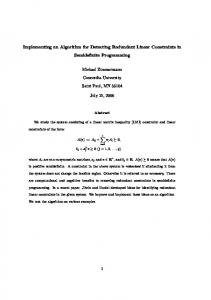
2. An embedded algorithm for accommodating synchronization problems in operational modal analysis The proposed algorithm builds upon the fundamentals of structural dynamics and operational modal analysis. In this section, the mathematical background is briefly explained and the steps of the algorithm are presented. 2.1 Mathematical background For detecting the time lag between two sets of structural response data, elements from the analysis of sinusoidal harmonic functions (signals) are adopted. Assuming the two nonsynchronized sinusoidal signals f(t) and g(t) with the same frequency ω, amplitudes A1 and A2, and phase angles φ and θ, respectively, plotted in Figure 1, the time lag τ between the two signals is calculated in Eq. 1. Signal 1
Signal 2
Amplitude
τ
Time (s)
Figure 1: Sinusoidal signals with a time lag τ.
2
f t A1 sint g t A2 sin t g t A2 sint
(1)
According to the theory of structural dynamics, structural response can be represented by the superposition of “vibration modes”, i.e. a sum of harmonic functions with different frequencies and oscillation amplitudes. Moreover, typically the response of a structure is dominated by one vibration mode, termed “fundamental mode”, which is usually the vibration mode with the lowest frequency. In experimental structural dynamics, a common objective is to identify the frequencies of vibration modes using digital signal processing techniques, such as the fast Fourier transform (FFT) (Cooley and Tukey, 1965). The FFT transforms a time series, which in this case is a set of structural response data, from the time domain into the frequency domain, i.e. the FFT of a time series is a function of frequency ω, as shown in Eq. 2. N 1
X k x n e
2ik
n N
k [0, N )
N k
n 0
N Δt
(2)
In Eq. 2, X is the kth element of the FFT transform of an N-point time series with elements x at frequency ω. The time step of the time series is denoted as Δt. From Eq. 2, it is evident that the FFT yields a complex-valued series, where each element represents a harmonic function. The modulus and the argument of each complex value correspond to the amplitude A and the phase angle δ of each harmonic function, as shown in Eq. 3. A k X k Re X k Im X k 2
Im X k Re X k
k arg X k arctan
2
k k Δt N
(3)
To estimate the time lag, for example, between two sets of structural response data, first the phase angles at the fundamental mode are retrieved. Since vibration modes describe physical oscillation, it follows that the harmonic functions of the fundamental mode from both sets of structural response data are either positively or negatively correlated. In terms of difference in phase angles, positive correlation is expressed as a difference between phase angles (“phase shift”) equal to 0, while negative correlation is reflected on a phase shift equal to π. Assuming adequate knowledge on the correlation among the sets of structural response data at the fundamental mode, the time lags are estimated using Eq. 1 with phase angles computed from Eq. 3. Since the values of the phase angles computed from Eq. 3 are restricted within the interval [0, 2π], the maximum phase shift cannot exceed 2π. Accordingly, the maximum time lag τ that can be estimated using the proposed algorithm is shown in Eq. 4.
2
3
T
(4)
From Eq. 4, it is evident that the proposed algorithm can detect time lags that do not exceed the fundamental period T of the structure. 2.2 Description of the embedded algorithm steps
For applying the embedded algorithm proposed in this paper, prior knowledge or estimate of the fundamental mode (“fundamental mode shape information”) of the structure is required. Specifically, the fundamental mode shape coordinates at the locations where structural response data is collected need to be estimated a priori. The sign difference among the mode shape coordinates indicates the correlation among the respective structural response data; coordinates of the same sign denote positive correlation, while coordinates of different sign express negative correlation. Accordingly, the expected phase shifts among the sets of structural response data at the fundamental mode are derived. The embedded algorithm performs the following steps: 1. Collect structural response data (acceleration response data) 2. Transform collected acceleration response data into the frequency domain via FFT 3. Retrieve the phase angle at the fundamental mode of vibration 4. Exchange phase angles at the fundamental mode of vibration with the rest of the sensor nodes 5. Calculate the time lag with respect to a pre-defined reference sensor node 6. Synchronize the collected acceleration response data according to the calculated time lag 7. Send Fourier values at previously defined frequencies (corresponding to vibration modes) from the synchronized acceleration response data to a central server for modal identification Finally, using the Fourier values of the synchronized sets of acceleration response data, the mode shapes are extracted by applying frequency domain decomposition (Brincker et al., 2000). In the following section, the implementation of the proposed algorithm into a wireless SHM system is described.
3. Implementation of the embedded algorithm into a prototype wireless SHM system
For implementing the embedded algorithm presented in this paper, a prototype wireless SHM system is devised. The SHM system is composed of wireless sensor nodes, a base station, and a centralized server. The tasks of detecting and accommodating time lags are entirely assigned to the sensor nodes, while the server is used for managing the SHM system, and the base station serves as a gateway between the sensor nodes and the server. The sensor nodes collect and transform acceleration response data, exchange the phase angles at the fundamental mode, calculate the time lags, synchronize their own collected acceleration response data, and transmit the Fourier values of the synchronized acceleration response data at frequencies corresponding to vibration modes to the server. The server initializes the SHM system, sends the fundamental mode shape information to the sensor nodes before applying the algorithm for the first time or when a change in structural state has been detected, and uses the Fourier values of the synchronized sets of acceleration response data to extract the mode shapes. The layout of the prototype SHM system is illustrated in Figure 2. 4
Figure 2: Layout of the prototype wireless SHM system for implementing the embedded algorithm.
The software for implementing the embedded algorithm, written in Java programming language, consists of two applications, one “host application” for the tasks of the server, and one “on-board application” for the tasks of the sensor nodes. The main class of the host application, named “FDDonDesktop”, initializes the wireless communication links between the base station and the sensor nodes and sends the fundamental mode shape information to the sensor nodes. Upon receiving the Fourier values of the synchronized sets of acceleration response data, the mode shapes are extracted by calling the “performFDD” method, which uses the “SingularValueDecomposition” class of the JAMA library for matrix operations (JAMA, 2011). The on-board application comprises the “FDDonNode” main class, which, first, initializes the wireless communication links with the base station and the reference sensor node. Next, the FDDonNode class handles the collection of acceleration response data as well as the FFT transform via the class “FrequencySpectrum”, which yields the Fourier series of amplitudes and phases, “FFT”, yielding the complex-valued FFT series, and “Complex” to handle complex number operations. Then, class “Synchronize” is called to calculate the time lag and to synchronize the collected acceleration response data according to the phase angle at the fundamental mode of the reference sensor node, whose reception is managed by the FDDonNode class. Finally, the FDDonNode class sends the Fourier values of the synchronized acceleration response data at the previously defined frequencies corresponding to vibration modes to the server. The validation of the prototype wireless SHM system with the proposed embedded algorithm is presented in the next section.
5
4. Validation tests
To showcase the capability of the embedded algorithm of detecting and accommodating synchronization problems, laboratory tests on a shear frame structure are devised. 4.1 Experimental setup
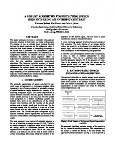
The four-story shear frame structure employed for the validation tests consists of 15 mm thick, 300 mm × 200 mm (length × width) aluminum plates resting on four 20 mm × 2 mm (width × thickness) aluminum columns. The plate-to-column connections are fully fixed, while the four columns are clamped to a base plate, which is, in turn, fixed to a solid block, ensuring full fixity at the base of the structure. The story height is 300 mm. The aluminum alloy used for the shear frame structure has a density of ρ = 2700 kg/m3 and a modulus of elasticity of E = 70 GPa. The wireless sensor nodes employed for the validation tests are the Oracle SunSPOTs (Oracle, 2010). The sensor nodes feature a 400 MHz ARM microprocessor programmable in Java, 512 kB RAM, and 4 MB flash memory. The sensor nodes are equipped with IEEE 802.15.4 radio transceivers leveraging the ZigBee protocol. In terms of sensing, a 3D digital output accelerometer, a temperature sensor, and a light sensor are integrated in each sensor node. The accelerometer samples at 125 Hz, with selectable measurement ranges of ±2 g, ±6 g, or ±8 g at a resolution of 8 bit. The experimental setup is shown in Figure 3.
Figure 3: Experimental setup with the laboratory shear frame structure and the wireless sensor nodes.
6
4.2 Description of the validation tests
Prior to conducting the laboratory tests, the fundamental mode shape information is loaded to the wireless sensor nodes. Subsequently, the shear frame structure is excited by deflecting the top story. The sensor nodes are tasked to start collecting acceleration response data, once a predefined threshold of 0.1g, determined by engineering judgment, is exceeded. Due to the different input acceleration level introduced at each story by the excitation, the 0.1g threshold is not exceeded simultaneously at all stories, thus resulting in synchronization discrepancies. The assessment of the algorithm is based on the comparison between the extracted mode shapes prior and after the synchronization. To provide a benchmark for this comparison, preliminary numerical analysis is performed on a numerical model of the laboratory test structure. The objective of the numerical analysis is to obtain estimates of the mode shapes. For the sake of simplicity, the analysis is restricted to the x-axis of the shear frame structure, which coincides with the length of the plates (300 mm). To verify the applicability of the algorithm, a total of two tests are performed. In both tests, the acceleration response data of the first story is taken as reference. The test results are summarized in Table 1. Table 1: Time lags between the acceleration response data of the frame structure stories with respect to the first (reference) story. Story
Time lag (ms) – Test 1
Time lag (ms) – Test 2
2
41
31
3
-10
48
4
-20
58
In the results of Table 1, negative values indicate that the respective set of acceleration response data needs to be delayed with respect to the reference set of acceleration response data. The extracted mode shapes from both tests, before and after the synchronization, are illustrated in Figures 4, 5, 6, and 7. The estimated mode shape from the numerical analysis is also plotted for comparison purposes.
Mode shape 1 (f = 1.526 Hz) Unsynchronized Test 1
Synchronized Test 2
Test 1
Numerical analysis
Test 2
1.00
1.00
1.00
1.00
1.00
0.91
0.91
0.90
0.91
0.87
0.64
0.70
0.69
0.70
0.63
0.41
0.38
0.40
0.41
0.33
Figure 4: 1st extracted mode shape at f = 1.526 Hz.
7
Mode shape 2 (f = 4.562 Hz) Unsynchronized Test 1
Synchronized Test 2
1.00
-1.18
1.00
1.00
0.12
0.17
Numerical analysis
Test 2 1.00
1.00
0.13 -0.25
Test 1
0.12
-0.02
-1.61
-0.90
-0.92
-1.02
-1.55
-1.09
-1.13
-0.96
Figure 5: 2nd extracted mode shape at f = 4.562 Hz. Mode shape 3 (f = 7.034 Hz) Unsynchronized Test 1
Synchronized Test 2
1.00
Test 1
-0.94
-1.25 0.49 1.62
1.00
1.00
1.00
-0.13
-1.06
-1.05
-0.76
-0.86
1.00 -1.42 -0.32 1.38
1.51
1.43
-1.43
Numerical analysis
Test 2
Figure 6: 3rd extracted mode shape at f = 7.034 Hz. Mode shape 4 (f = 8.789 Hz) Unsynchronized Test 1
Test 2
-2.10 -0.94
Test 1
-2.76
-2.26
1.00 -2.20
2.02
1.77 1.02
Numerical analysis
Test 2 1.00
1.00
1.00 -2.38
Synchronized
-1.12
1.00 -2.61
1.98 -1.04
3.44 -2.58
Figure 7: 4th extracted mode shape at f = 8.789 Hz.
From the results it is obvious that the synchronization performed by the embedded algorithms yields more realistic estimates of the mode shapes. As shown in Figure 4, the synchronization discrepancy effect is less obvious for the fundamental mode of the laboratory structure. This weak effect is attributed to the low frequency of the fundamental mode of vibration (f = 1.526 Hz) and, thus, to the long period of the respective frequency component 8
(T = 0.655 s) with respect to the time lags; the respective phase shifts among the unsynchronized sets of acceleration response data are low. In Figures 5, 6, and 7, the effect of the synchronization discrepancies is visible, and the synchronized signals are in good agreement with the results of the numerical analysis. Deviations among the extracted mode shapes and the estimated mode shapes of the numerical analysis are expected, due to modeling uncertainties, to imperfect excitation of higher vibration modes, and to measuring inaccuracies.
5. Summary and discussion
Decentralizing structural health monitoring (SHM) tasks is common practice in wireless SHM systems, owing to the processing power inherent to wireless sensor nodes. However, decentralization may lead to synchronization discrepancies among the sets of structural response data collected by the sensor nodes. Moreover, in system identification methods, typically employed in SHM, absolute synchronization among the sets of structural response data is a prerequisite for obtaining accurate estimates of structural parameters. In this paper, an embedded algorithm for accommodating synchronization problems in wireless SHM systems has been presented. The embedded algorithm is based on the theory of operational modal analysis and the expected relationship between the phase angles of frequency components corresponding to modes of vibration. First, assuming adequate knowledge on the fundamental (first) mode of vibration, which typically dominates structural vibration, the expected differences among the phase angles of the fundamental mode (phase shifts) are derived. Next, the sensor nodes collect acceleration response data and transform the data into the frequency domain via the fast Fourier transform. Then, using the expected phase shifts, each wireless sensor node calculates the time lag between its own set of acceleration response data and the set of structural response data from a predefined reference sensor node, whose phase angle at the fundamental mode is wirelessly communicated to all sensor nodes. Finally, the sensor nodes synchronize their own sets of acceleration response data based on the time lags and send the Fourier values at previously selected frequencies, corresponding to vibration modes, to a centralized server. The proposed algorithm has been implemented into a prototype wireless SHM system and validated through laboratory tests on a four-story shear frame structure. Numerical analysis on the frame structure has been performed to obtain estimates of the mode shapes, which have been used for comparison purposes. A total of two tests have been conducted by deflecting the laboratory structure at the top story and by letting the structure vibrate freely. The results from both tests have shown that the synchronization of the sets of acceleration response data according to the detected time lags yield mode accurate estimates of the mode shapes as compared with the numerical mode shapes. Moreover, the effect of synchronization problems has proven to be stronger in higher vibration modes, which are usually characterized by higher frequencies, and, thus, short periods with respect to the time lags. Future research will be directed towards investigating the performance of the embedded algorithm in cases of longer time lags. Moreover, the effect of the time lag on mode shapes with respect to the frequencies of the vibration modes can be quantified.
9
Acknowledgments
The authors gratefully acknowledge the support provided by the German Research Foundation (DFG) under grant SM 281/7-1. Also, the financial support through the DFG Research Training Group 1462 is gratefully acknowledged. Any opinions, findings, conclusions, or recommendations expressed in this paper are solely those of the authors and do not necessarily reflect the views of DFG or any other organizations and collaborators.
References Brincker, R., Andersen, P. & Zhang, L. (2000). Modal identification from ambient responses using frequency domain decomposition. In: Proc. of the 18th International Modal Analysis Conference (IMAC), San Antonio, TX, USA, 07/02/2000. Brincker R. & Brandt, A. (2011). Time synchronization by modal correlation. In: Proc. of the 4th International Operational Modal Analysis Conference, Istanbul, Turkey, 09/05/2011. Cooley, J. W. & Tukey, J. W. (1965). An algorithm for the machine calculation of complex Fourier series. Mathematics of Computation, 19 (90), pp. 297–301. Dragos, K. & Smarsly, K., (2015). A comparative review of wireless sensor nodes for structural health monitoring. In: Proc. of the 7th International Conference on Structural Health Monitoring of Intelligent Infrastructure, Turin, Italy, 01/07/2015. García-Palacios, J., Tirando-Andrés, F., Soria, J. M., Díaz, I. M. & Araujo, Á. (2015). Effects of time synchronization on operational modal analysis. In: Proc. of the 6th International Operational Modal Analysis Conference, Gijón, Spain, 12/05/2015. JAMA – A Java Matrix Package. Available at http://math.nist.gov/javanumerics/jama (Accessed: 29/03/2017). Lei Y., Shen W. A., Song Y. & Wang Y. (2010). Intelligent wireless sensors with application to the identification of structural modal parameters and steel cable forces: from the lab to the field. Advances in Civil Engineering 2010, pp. 1-10. Maes, K., Reynders, E., Rezayat, A., De Roeck, G. & Lombaert, G. (2016). Offline synchronization of data acquisition systems using system identification. Journal of Sound and Vibration, 381, pp. 264–272. Oracle Corp. (2009). Sun SPOT Theory of Operation, 1.5.0. Santa Clara, CA, USA: Sun Labs. Smarsly, K., Hartmann, D. & Law, K. H. (2012a). Structural Health Monitoring of Wind Turbines Observed by Autonomous Software Components – 2nd Level Monitoring. In: International Society for Computing in Civil and Building Engineering. In: Proc. of the 14th International Conference on Computing in Civil and Building Engineering, Moscow, Russia, 06/27/2012. Smarsly, K. & Law, K. H. (2013). Advanced Structural Health Monitoring based on Multi-Agent Technology. In: Zander, J. & Mostermann, P. (eds.). Computation for Humanity: Information Technology to Advance Society. Pp. 95-126, Boca Raton, FL, USA: CRC Press – Taylor & Francis Group, LLC. Smarsly, K., Law, K. H. & Hartmann, D. (2012b). Towards Life-Cycle Management of Wind Turbines based on Structural Health Monitoring. In: Proc. of the First International Conference on Performance-Based Life-Cycle Structural Engineering, Hong Kong, China, 12/05/2012. Sundararaman, B., Buy, U. & Kshemkalyani, A. D. (2005). Clock synchronization for wireless sensor networks: a survey. Ad Hoc Networks, 3 (3), pp. 281–323. Youn, S. (2013). A comparison of clock synchronization in wireless sensor networks. International Journal of Distributed Sensor Networks, 2013 Article ID: 532986, 10pp. Zhu, Y.-C. & Au, S.-K. (2017). Spectral characteristics of asynchronous data in operational modal analysis. Structural Control Health Monitoring, 2017 Article ID: e1981, 15pp.
10