IEEE TRANSACTIONS ON INSTRUMENTATION AND MEASUREMENT, VOL. 61, NO. 9, SEPTEMBER 2012
2469
An Implementation of SOPC-Based Neural Monitoring System Qijun Huang, Sheng Chang, Junqi Peng, Xueying Mao, You Zhou, and Hao Wang
Abstract—Neurosurgery is an important way to save life in clinical application. As a novel assistant technology for neurosurgery, neural monitoring is used to real-time observe neural state to prevent nerve injury. In this paper, a neural monitoring electronic system based on the methodology of system on programmable chip is presented. On the system, analog and digital circuits are integrated, whereas field-programmable gate array (FPGA) hardware and NIOS II embedded software are co-operated. Some key modules such as preprocessing box, self-adaptive amplification, digital filter, frequency measure, and secure digital card storage are described in detail, and the function of the system is verified by multiform examinations. Index Terms—Field-programmable gate array (FPGA), nerve monitoring, neural signal, system on programmable chip (SOPC).
I. I NTRODUCTION
I
N RECENT years, as one of the important clinical surgeries, neurosurgery has rapidly developed. However, on surgery, a nerve may be injured by mistake. To avoid these hidden dangers, neural monitoring technology has become a powerful tool on operation. By monitoring nerve stimulus signal and corresponding response signal, surgery can be safer. There are two kinds of widely used electromyogram (EMG) [1], [2] nerve monitoring method, namely, spontaneous EMG monitoring [3] and triggered EMG monitoring [4], [5]. The first one is also called free-tracing EMG, which continuously records electrical activity of muscles. Once a nerve is stimulated by mechanical stretching on surgery, the muscles dominated by that nerve will contract and a response electrical signal can be monitored. For triggered EMG, an electrical stimulation is put on a nerve (directly or indirectly) to observe the response of a muscle. In addition to this, many specific monitoring methods are used, for instance, ECG monitoring [6], EEG monitoring during carotid surgery [7], depth electrode monitoring on Parkinson surgery [8], and evoked potentials on spine procedures [9].
Manuscript received September 6, 2011; revised February 2, 2012; accepted February 3, 2012. Date of publication April 3, 2012; date of current version August 10, 2012. This work was supported by Hubei Provincial Natural Science Foundation of China under Grant 2011CDB272. The Associate Editor coordinating the review process for this paper was Dr. Kurt Barbe. Q. Huang, S. Chang, J. Peng, and X. Mao are with the Department of Electronics Science and Technology, School of Physics and Technology, Wuhan University, Wuhan 430072, China (e-mail:
[email protected]). Y. Zhou is with the Tianyou Affiliated Hospital of Wuhan University of Science and Technology, Wuhan 430070, China. H. Wang is with the Institute of Microelectronics and Information Technology, Wuhan University, Wuhan 430072, China. Color versions of one or more of the figures in this paper are available online at http://ieeexplore.ieee.org. Digital Object Identifier 10.1109/TIM.2012.2190332
Generally speaking, EMG methods are both based on the electrical conductivity [10] property of neurons. They are normally combined to accurately locate the situation of a nerve. This way, neural monitoring can help a surgeon to find a motor nerve and a nerve root, seize the status of a nerve, and avoid injury in surgery [11]. To achieve the above goal, two kinds of equipment are applied to monitor EMG. The first one is direct EMG recording system, in which electronic response signal caused by muscle action is directly recorded and shown on oscilloscope real time. The other one is based on a pressure sensor, in which muscle’s mechanical action is sampled by the sensor and then transferred to an electrical signal. Both of them can alarm when a nerve is stimulated and corresponding muscle action is brought, but the direct EMG recording is more sensitive. Our design belongs to the triggered direct EMG monitoring. Differing from commercial EMG monitoring equipment pieces such as Neurosign 100/400/800/1000 series [12], our neural monitoring system is system on programmable chip (SOPC) based. Signal capture and amplification are realized by an analog circuit, whereas signal process, signal analysis, and man–machine interface control are implemented on a fieldprogrammable gate array (FPGA) digital platform. In addition to this, to pursue high performance and good expandability, an embedded CPU, i.e., NIOS II [13], is employed and system tasks are partitioned to hardware and software rationally. This way, our design gains two novelties. The first is the flexible framework. Equipping suitable electrodes and adjusting parameters of a preprocessing analog circuit, our system can be used for different kinds of medical signal monitoring. The second is the good expandability. Since an SOPC structure has embedded software ability, our system is easy to update for indepth signal analysis algorithm realization without the redesign of hardware. In Section II, the function of this neural monitoring system is described, whereas its architecture and design are given in Section III. Section IV shows the implementation and verification of the system, and finally, the conclusion is drawn in Section V. II. F UNCTION D ESCRIPTION A. Application Scene According to the electrical conduction properties of a nerve, given a small-current stimulus, which is safe and acceptable for a nerve, a neural electronic signal will be generated and acts on the muscle associated with the stimulated nerve [14]. Neural monitoring system should generate a stimulus and collect signal from the muscle. If the response signal from an organism,
0018-9456/$31.00 © 2012 IEEE
2470
IEEE TRANSACTIONS ON INSTRUMENTATION AND MEASUREMENT, VOL. 61, NO. 9, SEPTEMBER 2012
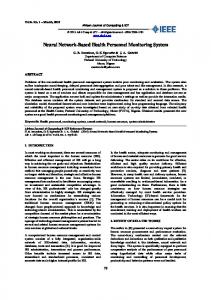
Fig. 1. Function description of neural monitoring system.
which is the same frequency signal as stimulus response (may be strong) or high-frequency signal, can be correctly received, this means that the monitored nerve is safe; if the response signal cannot be received, this means that the nerve has been damaged or the muscle is not associate with the monitored nerve. Through observing the above statuses, a doctor can judge the safety of surgery and control it. B. Function Design On the basis of above application scene, a neural monitoring system should provide the following functions such as generate stimulus signal, collect response signal from the muscle, process the received signal, analyze information from it, and notify the doctor the analysis result. Fig. 1 shows the function description. According to Fig. 1, the function of our system is designed as follows. 1) Stimulus signal generation. A current pulse on milliampere magnitude is chosen as the stimulus signal, and its safety has been verified by many applications [15]–[17]. The pulsewidth is 0.2 ms, pulse interval can be adjusted from 1/3 to 1/30 s (3–30 Hz), and pulse magnitude can be adjusted from 0.05 to 5 mA. 2) Signal process. Since the response signal from the muscle is weak, it should be first amplified by preamplification, which is isolated from the main frame and near the organism to decrease noise. After this, a self-adaptive amplifier is needed to further enlarge the response. Then, it should be converted to digital signal, and subsequent signal analysis could be done. To guarantee the quality of a signal, analog and digital filters are employed. Based on the SOPC platform, magnitude and frequency information of a signal are extracted. 3) Result notification and record. On surgery, a doctor should get information from the analysis result of a monitoring system. In our design, two methods are available. One is visual notification. An oscilloscopelike display is designed, and from it, the doctor can observe the wave pattern of the response signal directly. Considering perhaps that the doctor has no time looking at the screen continuously on the surgery, an audible alarm is also designed as the other notification method. The frequency and volume of an audible alarm vary with the change of response signal; hence, the doctor can judge the status by hearing. In addition to those two notifications, the collected signal can be stored in a secure digital (SD) card for the purpose of analysis after surgery.
Fig. 2.
Architecture of neural monitoring system.
III. A RCHITECTURE AND M ETHODOLOGY A. System Architecture To fulfill above function description, our neural monitoring system includes analog and digital circuits. For the digital circuit, traditionally, a digital signal processor (DSP) is needed to realize signal analysis and a microcontrol unit is needed to glue logic and control the circuit. However, this way is complex and lacks flexibility. In this paper, we successfully construct an SOPC platform on FPGA to overcome this problem. In this method, module control and signal analysis are realized by FPGA’s parallel hardware, which is more efficient compared to DSP’s serial process, and now widely used on pulse signal measurement [18]–[20]. In addition to this, an embedded CPU, i.e., NIOS II, is built. Through it, complicated task for hardware can be accomplished by a software method [21], which is popular for signal measurement and analysis [22]–[24]. Hardware and software are combined on a single FPGA chip; thus, the system is simplified. The structure of our neural monitoring system is described, as shown in Fig. 2. In Fig. 2, the combination of the analog and digital circuits is obviously shown. Analog stimulus current signal is converted from voltage signal, which is generated by digital hardware on FPGA. Two-way response signals are collected by an analog preprocessing circuit. Before they are converted to digital signal for analysis, the procedure of self-adaptive amplification has been controlled by digital hardware on FPGA. Audible alarm, which is the output on a speaker, is also generated by the digital circuit. For the digital circuit, the SOPC platform is also clearly shown. The function of module control, signal analysis, and display and result storage are fulfilled by the NIOS II embedded CPU and hardware digital circuit. FPGA controls the enlargement factor of the adaptive amplifier to fit A/D converter’s measuring range. A digital filter is designed to depress noise from the power supply. After this, frequency and magnitude information of a signal are measured by digital technology. Then, the waveform and its parameters are displayed on an LCD screen. Finally, measured data are real-time stored in an SD card for the purpose of further contrast and analysis. Through Avalon bus, NIOS II controls all these works and complete some of them directly, such as SD card storage, frequency measure, and so on.
HUANG et al.: IMPLEMENTATION OF SOPC-BASED NEURAL MONITORING SYSTEM
Fig. 3.
2471
Block diagram of preprocessing box.
B. Key Issues About the Analog Circuit For stimulus signal and collected response signal, a suitable electrode is important to guarantee the quality of a signal. In our system, two channels are designed. For every channel, there are two stimulus electrodes (i.e., V+ and Vref ) and three response electrodes (i.e., V+ , V− , and Vref ). On prototype stage, an acupuncture needle is chosen as the electrode because it has low contact resistance and little interference to organism. A coaxial cable is used to link the electrode and a bayonet nut connector for masking noise jamming. A preprocessing box is an analog circuit module to collect and preamplify response signal. Since this module is the firststage circuit, it is designed as an individual box. It is divided from the main processing board and put nearby the organism for the purpose of preventing signal attenuation and depressing noise. In addition, a coaxial cable is used to link it and the mainboard. The structure is described as Fig. 3. In Fig. 3, the preamplifier is the critical component. As the first step to process the weak muscle response signal, high input impedance, high gain, high common-mode rejection ratio, low noise, and low drift are considered in the design. An input buffer is formed by a negative voltage feedback, which has enormous input resistance. It not only isolates organism and circuit effectively but also masks the instability caused by the change of signal resistance. After this, an instrumentation amplifier is used to satisfy the high standard of weak signal amplification. Active filters follow the preamplifier because various noises caused by circumstance or organism itself will feed in response collection circuit. By experiments, the low-frequency cutoff is set as 1 Hz and the high-frequency cutoff is set as 1.4 kHz, whereas the enlargement factor of active filters is 2. An optoelectric isolator, i.e., ISO124, is used as a bridge between preamplify circuit and mainboard processing circuit to avoid the disturbance that comes from the mainboard and the potential risk of human hurting. Self-adaptive amplification is another key issue. After preamplification, the response signal is enlarged about 100 times, but its magnitude can only reach millivolt order. This level does not meet the requirements of the A/D converter and should be further amplified. However, the question is after preamplification; magnitude difference between big and small response signals is also enlarged 110 times. If a signal is uniformly amplified again at both cases, a big signal will overrun the measuring range of the A/D converter. To resolve this problem, self-adaptive amplification is designed in our system. It is implemented by the cooperation of a programmable amplifier, A/D converter, and FPGA. FPGA checks the peak value of the A/D convert result and judges whether it is over the setting high_threshold. If
Fig. 4. Control flow of self-adaptive amplification. TABLE I H ARDWARE /S OFTWARE PARTITION OF O UR SOPC D ESIGN
it is true, FPGA reduces the gain of the programmable amplifier. In a special case, if the gain is too small that the convert result is below the setting low_threshold, which is difficult for following signal analysis, the gain of the programmable amplifier will be recovered. For our design, a (−5 V, +5 V) 12-bit A/D converter, i.e., MAX197, is chosen; the high_threshold is set as 0x7FF; and the low_threshold is set as 0x01B. The control flow of selfadaptive amplification is shown in Fig. 4. C. SOPC Design of the Digital Circuit In Fig. 2, one can see that the digital circuit should complete many functions such as digital filter, signal analysis (magnitude measure and frequency measure), stimulus voltage generation, audio signal generation, result display, and result SD card storage. Based on the SOPC platform, hardware/software codesign is our method to fulfill the above functions. As a general principle, hardware/software partition of system on chip [25], [26] should tradeoff between speed, area, power cost, and the complexity of the design. Different from it, since SOPC is constructed on FPGA, area is not very critical, and power cost is mostly decided by the FPGA device itself. Therefore, process speed and complexity of implementation are our key criteria for hardware/software partition. By experiments, we found that SD card storage needs to create a file system, whereas the calculation on frequency measure is complex for hardware realization. Therefore, these two functions are fulfilled by software and others are implemented by hardware. The partition is listed in Table I.
2472
IEEE TRANSACTIONS ON INSTRUMENTATION AND MEASUREMENT, VOL. 61, NO. 9, SEPTEMBER 2012
Fig. 6.
Main frame of analog neural monitoring system.
Fig. 7.
Appearance of preprocessing box.
Fig. 8.
Main frame of SOPC-based neural monitoring system.
Fig. 5. Scheme of equal precision frequency measure.
Similar as the description of the analog circuit, key modules of digital SOPC design are discussed as follows. A digital filter is used to further depress noise from the power supply. Considering the simplicity of implementation, a twoorder band-stop IIR filter for 50 Hz is designed by Verilog HDL [27]. Compared to a FIR filter, it can complete filtering on a lower order. The coefficient of the IIR filter is calculated by a finite difference approximation toolbox on MATLAB. Because the IIR filter is constructed by multiply and add operations, we choose the embedded hardware DSP resources on FPGA, but not the software method, to realize it. A gist should be pointed out that, since fixed-point DSP resources are more common on FPGA, here we represent float-point data by a fixed-point method. To ensure the accuracy of calculation, the coefficient of IIR is enlarged by 250 . As shown in the above description, since self-adaptive amplification is employed on the analog circuit, magnitude measure of the response signal is not equal to the measure of A/D’s result but should consider the gain of the programmable amplifier. The maximum and minimum values of reverted muscle response signal are extracted by digital wave judge, in which a simple algorithm is used to remove glitch. Since these operations are not complex and must act on every data of response signal in real time, it is realized by hardware, but not software, to improve the process speed. For frequency measure, the traditional method is periodic time measure. However, for pulse signal (such as our response signal), the error of periodic time is too big. Therefore, for better accuracy, we design an equivalent precision measure on NIOS II. As shown in Fig. 5, the measure time is not a pulse period but a setting approximate time D, and it is synchronized by the posedge of measured pulse fx to generate an accurate measure time T . A measure clock fm is given by a phase-locked loop. In the range of T , the number of measured pulse Nx and the number of measure clock Nm are recorded. Obversely, we have Nx · T x = N m · T m .
(1)
This means
error does exist, but the frequency of the measure clock is high enough (i.e., 200 MHz in our case); thus, the error is minute and the accuracy of measure is high. The high-accuracy calculation of (2) is not easy for hardware because Nx is a big value for high-accuracy measure; hence, we realize it by software on NIOS II. SD card storage is another module realized by software on the SOPC platform because it must use a file system that cannot be realized by hardware. NIOS II embedded CPU supports a file allocation table file system. We complete data storage on the SD card through Avalon bus and a serial peripheral interface controller. When a storage command is given by the doctor, the data of response signal are saved on SRAM temporarily through Avalon bus. Then, NIOS II executes write operation to the SD card, and the data are transferred to the SD card as a file. This file can be read by a PC for further contrast and analysis. IV. I MPLEMENTATION AND T ESTS
fx =
Nx × fm . Nm
(2)
In Fig. 5, one can see that, because T is synchronized by fx , there is no quantization error on Nx . For Nm , quantization
A. Implementation As the foundation of this SOPC-based neural monitoring system, we had completed an analog neural monitoring system [28]. It realizes nerve monitoring by an analog signal process
HUANG et al.: IMPLEMENTATION OF SOPC-BASED NEURAL MONITORING SYSTEM
2473
TABLE II S YNTHESIS R ESULT OF O UR SOPC D ESIGN
method. The whole system is constructed by an analog circuit; for instance, the magnitude of response signal is expressed by the number of bright LEDs. It is a fulfilling animal experiment on Hanyang Affiliated Hospital of Wuhan University of Science and Technology. On the experiment, electrodes are inserted to the nerve of a rabbit’s foot and muscle response signal is collected. The measuring result is agreed with commercial EMG monitoring equipment, i.e., Neurosign 100. Fig. 6 lists its main frame. Based on the analog neural monitoring system, we design this SOPC-based neural monitoring system. Preprocessing box is a general module of the two generations. It is listed in Fig. 7 where two channels can be seen. The main frame of the SOPC-based neural monitoring system is shown in Fig. 8. Compared with the previous analog one, the SOPC method improves system’s performance obviously. Digital magnitude measurement is more accurate, and the response wave can be exactly shown. Embedded software component extends valuable functions such as signal storage, frequency measurement, and further signal analysis. As described in Section III, the whole SOPC architecture is completed on an FPGA chip. Table II gives the implementation result on the FPGA device, i.e., Altera’s Cyclone II EP2C20Q240. In order to verify the performance of our SOPC-based neural monitoring system, multiform tests have been done. Since it is on the stage of prototype research, the experiments are partial to electrical properties test. However, on the experience of the analog neural monitoring system’s animal experiments, we have a rational optimism about this SOPC one. Function tests of analog and digital circuits are arranged on signal flow as follows. First, results of the preprocessing box and main amplification (self-adaptive amplification) are given. Then, results of digital functions are shown.
TABLE III T EST R ESULT OF P REPROCESSING B OX
TABLE IV T EST R ESULT OF S ELF -A DAPTIVE A MPLIFICATION
B. Test Results of the Analog Circuit The preprocessing box collects and amplifies muscle response signal, which is the base of signal process and analysis. Both standard signals and response signals from the organism are input to test the preprocessing box’s performance. The results are listed in Table III. For standard signals, sinusoidal wave, square wave, and pulse are representatives. Since the new system is on the stage of electrical test, no human or massive animal test is done. EMG signals from five bullfrogs are tested to certify that actual organism signal can be collected. In Table III, EMG signal1 means the electronic pulse signal generated by bullfrog’s autonomous leg flutter, and EMG signal2 means the electronic pulse signal generated by external force that pulls bullfrog’s leg. In Table III, one can see for different signal forms, signal frequencies (in the work range), and signal magnitudes that the gain of the preprocessing box
Fig. 9. Linearity of self-adaptive amplification.
is stabilized on about 110, whereas the maximum error is just only 0.81%. Self-adaptive amplification is the tiepoint of analog and digital circuits, and its performance is tested, as shown in Table IV. The response for different waveforms and frequencies (in the work range) is the as same as the preprocessing box; hence, only the test data of a 30-Hz sinusoidal wave is shown as an example to observe the change of enlargement factor on different signal magnitudes. In Table IV, one can see, with the increase in input, that the gain of self-adaptive amplification varies on a decreasing trend; it indicates the self-adaptive amplification. To further test its linearity, outputs in different cases are normalized by gain (40 is select as a standard); Fig. 9 shows
2474
IEEE TRANSACTIONS ON INSTRUMENTATION AND MEASUREMENT, VOL. 61, NO. 9, SEPTEMBER 2012
Fig. 10. ModelSim result of IIR filter. Fig. 12.
Fig. 11. Frequency measure result by NIOSII.
the result; the maximum deviation from linearity is 5.06%; and the average deviation is only 1.18%, which exhibits good linearity of this self-adaptive amplification. C. Test Results of the Digital Circuit Following the description in Section III, the test results of the digital filter, frequency measure, and SD card storage are selected from the digital design to show the verification of hardware and software of SOPC. For the digital filter, since it is realized by a Verilog hardware description language, the simulation result of ModelSim is given in Fig. 10. This IIR filter attenuates the 50-Hz power noise by 24 dB. Associating with the analog low- and high-pass filters in the preprocessing box, noise can be perfectly eliminated. Using the equivalent precision method, the NIOS II embedded CPU measures accurate frequency of a response signal. Fig. 11 gives the measure result for a 40-Hz pulse signal, in which the measure clock fm is set as 200 MHz, and the values of fx , Nx , and Nm are shown in columns orderly. Analyzing the result, the accuracy of frequency measure can achieve 0.2%. For SD card storage verification, we design a simple proof scheme. First, a test bench signal wave is stored on the SD card and is displayed on an oscilloscope synchronously. Second, read the signal from the SD card and plot the wave by MATLAB. Finally, compare the wave on the oscilloscope and from MATLAB. The result is shown in Fig. 12. That two signals are consistent, which means that SD card storage is right. V. C ONCLUSION In this paper, an SOPC-based neural monitoring system, which can help doctors to control the surgery, has been introduced. It combines with analog and digital circuits. Furthermore, hardware and software are codesigned by SOPC method on an FPGA platform. Some key modules such as preprocessing box, self-adaptive amplification, digital filter, fre-
SD card storage verification.
quency measure, and SD card storage are described in detail to uncover the function and architecture of the neural monitoring system. Under the frame of SOPC, some complex operations for hardware are realized by software easily. In addition to the basic application on surgery, the hardware/software cooperation plant of our system keeps a big margin for further biologic signal process and analysis, such as fast Fourier transform (FFT) and wavelet transforms, and autoregressive model signal power spectrum analysis, and it has a brilliant outlook on medical attendance and biology research. R EFERENCES [1] V. T. Inman, H. J. Ralston, J. B. De, C. M. Saunders, M. B. Bertram Feinstein, and E. W. Wright, “Relation of human electromyogram to muscular tension,” Electroencephalogr. Clin. Neurophysiol., vol. 4, no. 2, pp. 187–194, May 1952. [2] W. T. Koos, C. Matula, and J. Lang, Color Atlas of Microneurosurgery of Acoustic Neurinomas. New York: Georg Thieme Verlag, 2002. [3] D. R. Hubbard and G. M. Berkoff, “Myofascial trigger points show spontaneous needle EMG activity,” SPINE, vol. 18, no. 13, pp. 1803–1807, Oct. 1993. [4] R. W. Fields, “Electromyographically triggered electric muscle stimulation for chronic hemiplegia,” Arch. Phys. Med. Rehabil., vol. 68, no. 7, pp. 407–414, 1987. [5] G. H. Kraft, “EMG-triggered muscle stimulation,” Arch. Phys. Med. Rehabil., vol. 69, no. 2, p. 149, 1988. [6] M. E. Nygårds and J. Hulting, “An automated system for ECG monitoring,” Comput. Biomed. Res., vol. 12, no. 2, pp. 181–202, Apr. 1979. [7] Y. Shang, R. Cheng, L. Dong, S. J. Ryan, S. P. Saha, and G. Yu, “Cerebral monitoring during carotid endarterectomy using near-infrared diffuse optical spectroscopies and electroencephalogram,” Phys. Med. Biol., vol. 56, no. 10, pp. 3015–3032, 2011. [8] J. Yelnik, P. Damier, S. Demeret, D. Gervais, E. Bardinet, B. P. Bejjani, C. Francois, J. L. Houeto, I. Arnulf, D. Dormont, D. Galanaud, B. Pidoux, P. Cornu, and Y. Agid, “Localization of stimulating electrodes in patients with Parkinson disease by using a three-dimensional atlas-magnetic resonance imaging coregistration method,” J. Neurosurg., vol. 99, no. 1, pp. 89–99, 2003. [9] S. S. Haghighi, “Monitoring of motor evoked potentials with high intensity repetitive transcranial electrical stimulation during spinal surgery,” J. Clin. Monit. Comput., vol. 17, no. 5, pp. 301–308, 2002. [10] L. Y. Wei, “A new theory of nerve conduction,” IEEE Spectr., vol. 3, no. 1, pp. 123–124, 1966. [11] K. L. Kilgore and N. Bhadra, “High frequency mammalian nerve conduction block: simulations and experiments,” in Proc. 28th Annu. Int. Conf. IEEE EMBS, New York, Aug. 30–Sep. 3, 2006 pp. 4971–4974. [12] The Magstim Company Limited, What are the differences between the Neurosign 100, 400, 800 and 1000?, Carmarthenshire, UK2010. [13] NIOS II Processor Reference Handbook, Altera Corp., San Jose, CA, 2006. [14] M. Y. Woo and B. Campbell, “Asynchronous firing and block of peripheral nerve conduction by 20 Kc alternating current,” Bull. Los Angeles Neurol. Soc., vol. 29, pp. 87–94, 1964. [15] S. Plevnik, D. B. Vodušek, P. Vrtaènik, and J. Jane, “Optimization of pulse duration for electrical stimulation in treatment of urinary incontinence,” World J. Urol., vol. 4, no. 1, pp. 22–23, 1986. [16] C. A. Miller, P. J. Abbas, B. K. Robinson, K. V. Nourski, F. Zhang, and F. C. Jeng, “Auditory nerve fiber responses to combined acoustic and
HUANG et al.: IMPLEMENTATION OF SOPC-BASED NEURAL MONITORING SYSTEM
[17]
[18] [19] [20]
[21] [22]
[23] [24] [25] [26] [27] [28]
electric stimulation,” J. Assoc. Res. Otolaryngol., vol. 10, no. 3, pp. 425– 445, 2009. Y. L. Lo, Y. F Dan, Y. E. Tan, A. Teo, S. B. Tan, W. M. Yue, C. M. Guo, and S. Fook-Chong, “Clinical and physiological effects of transcranial electrical stimulation position on motor evoked potentials in scoliosis surgery,” Scoliosis, vol. 5, no. 3, 2010. doi:10.1186/1748-7161-5-3. R. Szplet, J. Kalisz, and R. Szmanowski, “Interpolating time counter with 100ps resolution on a single FPGA device,” IEEE Trans. Instrum. Meas., vol. 49, no. 4, pp. 879–883, Aug. 2000. R. Szplet and K. Klepacki, “An FPGA-integrated time-to-digital converter based on two-stage pulse shrinking,” IEEE Trans. Instrum. Meas., vol. 59, no. 6, pp. 1663–1670, Jun. 2010. S. Buzzetti, M. Capou, C. Guazzoni, A. Longoni, R. Mariani, and S. Moser, “High-speed FPGA-based pulse-height analyzer for high resolution X-ray spectroscopy,” IEEE Trans. Nucl. Sci., vol. 52, no. 4, pp. 854–860, Aug. 2005. M. Finc and A. Zemva, “Profiling soft-core processor applications for hardware/software partitioning,” J. Syst. Archit., vol. 51, no. 5, pp. 315– 329, May 2005. S. Sanchez-Solano, A. J. Cabrere, I. Baturone, F. J. Moreno-Velo, and M. Brox, “FPGA implementation of embedded fuzzy controllers for robotic applications,” IEEE Trans. Ind. Electron., vol. 54, no. 4, pp. 1937– 1945, Aug. 2007. A. Lakshmikanth and M. M. Morcos, “A power quality monitoring system: a case study in DSP-based solutions for power electronics,” IEEE Trans. Instrum. Meas., vol. 50, no. 3, pp. 724–731, Jun. 2001. V. Medina, O. Rivera, D. Oviedo, E. Dorronzoro, and I. Gomez, “Open and flexible embedded system applied to positioning and telecontrol,” IEEE Trans. Instrum. Meas., vol. 60, no. 12, pp. 3816–3823, Dec. 2011. H. Chang, L. Cooke, M. Hunt, G. Martin, A. McNelly, and L. Tood, Surviving the SOC Revolution: Platform-Based Design. Noewell, MA: Kluwer, 1999. L. Benini and G. De Micheli, “Networks on chips: A new SoC paradigm,” Computer, vol. 35, no. 1, pp. 70–78, Jan. 2002. S. Palnitkar, Verilog HDL: A Guide to Digital Design and Synthesis. Englewood Cliffs, NJ: Prentice-Hall, 1996. G. Jiang, Q. Huang, X. Li, X. Mao, and F. Cheng, “Design of an amplifier system for neural electrode,” Electron. Technol., vol. 36, no. 7, pp. 37–38, 2009.
Qijun Huang was born in Guangxi, China, in 1965. He received the B.S. degree in semiconductor physics and the Ph.D. degree in microelectronics and solid-state electronics from Wuhan University, Wuhan, China, in 1986 and 2010, respectively. He is currently with the School of Physics and Technology, Wuhan University. His current research focuses on the design of embedded system and measuring instrument.
Sheng Chang received the B.S. degree in applied physics and the M.S. and Ph.D. degrees in microelectronics and solid-state electronics from Wuhan University, Wuhan, China, in 2002, 2004, and 2009, respectively. He is currently with Wuhan University. His research interests mainly include image processing techniques, embedded system design, and fieldprogrammable gate array application.
2475
Junqi Peng received the B.S. degree in physics from Hunan University of Science and Engineering, Changsha, China, in 2009. He is currently working toward the M.S. degree in integrated circuit engineering at Wuhan University, Wuhan, China. His current research focuses on application of field-programmable gate array.
Xueying Mao received the B.S. degree in electronic science and technology in 2008 from Wuhan University, Wuhan, China, where she is currently working toward the M.S. degree in microelectronics and solid-state electronics. Her current research focuses on the design of a digital electronic system.
You Zhou received the B.S. degree in medical treatment and the M.S. and Ph.D. degrees in neurosurgery from Tongji Medical College, Wuhan, China, in 1987, 1990, and 1993, respectively. From 1993 to 2007, he was with Tongji Medical College, and he is currently with the Tianyou Affiliated Hospital of Wuhan University of Science and Technology, Wuhan. His research area is neurosurgery.
Hao Wang was born in Henan, China, in 1983. He received the B.S. degree in electronic engineering and the M.S. and Ph.D. degrees in microelectronics and solid-state electronics from Wuhan University, Wuhan, China, in 2003, 2006 and 2009, respectively. He is currently with Wuhan University. His research interests mainly include the design of a fieldprogrammable gate array-based system.