This article has been accepted for publication in a future issue of this journal, but has not been fully edited. Content may change prior to final publication. Citation information: DOI 10.1109/JESTPE.2017.2780918, IEEE Journal of Emerging and Selected Topics in Power Electronics
1
An Improved Design of Current Controller for LCL-Type Grid-Connected Converter to Reduce Negative Effect of PLL in Weak Grid Shiying Zhou, Student Member, IEEE, Xudong Zou, Member, IEEE, Donghai Zhu, Student Member, IEEE, Li Tong, Yingying Zhao, Yong Kang, and Xiaoming Yuan, Senior Member, IEEE Abstract—For three-phase LCL-type grid-connected converter, when it is attached to weak grid, current control interacts with phase-locked loop (PLL) via point of common coupling (PCC) voltage. Consequently, PLL dynamic might deteriorate grid current control and even result in system instability. However, the conventional design method of current controller neglects the impact of PLL, and therefore, it is hard for the current controller to mitigate the negative effect of PLL. In this paper, an improved design of current controller, i.e., PI controller and capacitor current feedback active damping, is proposed to reduce the negative effect of PLL on current control. First, a small-signal impedance model is developed to analyze the impact of PLL on current control. Then, the effect of current controller parameters on the converter output impedance is analyzed, and a design guideline to improve the current controller parameters is presented. With the improved parameters, in precondition of satisfying system stability margin under both stiff and weak grid, the negative effect of PLL on current control can be effectively mitigated without employing additional control strategies. Furthermore, the current control has a strong robustness against wide-range variation of grid impedance. Finally, the experiment demonstrates the effectiveness of the proposed design method. Index Terms—Current controller, grid-connected converter, phase-locked loop, small-signal impedance model, weak grid.
W
I. INTRODUCTION
ITH the increasing penetration of renewable energy into the grid, power quality and stability issues have been attracting more and more attention. As an interface between the Manuscript received January 31, 2017; revised June 15, 2017; revised August 24, 2017; accepted November 20, 2017. Date of current version December 5, 2017. (Corresponding Author: Xudong Zou.) This work was financially supported in part by the National Key R&D Program of China under Award 2017YFB0902000, in part by State Grid Corporation of China Science and Technology Project: Stability Analysis and Control of Power System Integrating Renewable Energy Generation Bases Delivered by HVDC Transmissions, and in part by the National Natural Science Foundations of China (NSFC) under Award 51477064. S. Zhou, X. Zou, D. Zhu, Y. Kang and X. Yuan are with the State Key Laboratory of Advanced Electromagnetic Engineering and Technology, School of Electrical and Electronic Engineering, Huazhong University of Science and Technology, Wuhan 430074, China (e-mail:
[email protected];
[email protected];
[email protected];
[email protected];
[email protected]). L. Tong is with the Zhejiang Electric Power Corporation Research Institute, Hangzhou 310014, China (e-mail:
[email protected]). Y. Zhao is with the State Grid Anhui Economic Research Institute, Hefei 230000, China (e-mail:
[email protected]).
distributed power generation system (DPGS) and grid, grid-connected converter plays a key role in injecting high quality power into the grid [1]-[3]. For three-phase grid-connected converter, LCL-filter is usually used to attenuate switching harmonics [4], [5], and the common control method for LCL-type grid-connected converter is the current control with proportional-integral (PI) controller in dq frame [6]. Moreover, the capacitor current feedback active damping is usually used to suppress LCL filter resonance [4], [7]. Since the renewable energy resources are usually located far from load centers, the public grid exhibits the weak grid characteristics, which results that the grid impedance cannot be ignored. Generally, the short circuit ratio (SCR) is usually used to describe the stiffness of the grid, that is, when 2≤SCR≤3, the grid is weak, and when SCR0°, GM>0dB of (A.2), the left area of vertical line is fc0dB of (23), the left area of vertical line is fc0°, and as large as possible. The first criterion can be satisfied when system has enough PM and GM by properly designing the current controller. The second criterion is discussed here. In order to take the worst situation into consideration, this paper supposes that grid impedance is a pure inductance, because the resistor in the grid impedance will increase the PMcross and helps to stabilize the system [5]. Therefore, the phase of grid impedance is always 90°, and then PMcross can be expressed as (26) [5].
Magnitude (dB)
7
0
Zgqq(s)
-90
-180 101
PMcross Zqq(s)
102 103 104 Frequency (rad/s) (b)
Fig. 10. Bode diagrams of the dq-axis converter output impedance with different current reference and SCR. (a) Zcon(s). (b) Zqq(s).
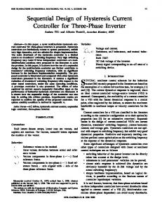
Fig. 11 shows the effect of controller parameters (Kp, Ki and Kcp) variation on Zqq(s) when SCR=2, the controller parameters are selected according to the shaded area of Fig. 8. It can be seen that, 1) Zqq(s) nearby fcross is influenced by the change of both Kp and Ki. 2) When Ki and Kcp are constant, on the condition of satisfying the static stability margin constrains (Fig. 8), with the increase of Kp, fcross increases, the PMcross increases, and the stability of the system increases. 3) When Kp and Kcp are constant, on the condition of satisfying the static stability margin constrains (Fig. 8), with the decrease of Ki, fcross decreases, the PMcross increases, and the stability of the system increases. 4) When Ki and Kp are constant, Kcp has a greater effect on the impedance nearby LCL filter resonance frequency, while has a little effect on the impedance phase nearby fcross, that is because the LCL filter resonance frequency is far away from fcross. However, if it is applied to high power system, the LCL filter resonance frequency will lower and close to fcross. As a result, the Kcp may have greater effect on the impedance phase nearby fcross, and the parameters improved design might be more complicated. Therefore, in the region of Fig. 8, the larger Kp, smaller Ki and suitable Kcp are conducive to reduce the negative influence of PLL on the grid current control under weak grid. Consequently, the phase of Zqq(s) nearby fcross can be
2168-6777 (c) 2017 IEEE. Personal use is permitted, but republication/redistribution requires IEEE permission. See http://www.ieee.org/publications_standards/publications/rights/index.html for more information.
This article has been accepted for publication in a future issue of this journal, but has not been fully edited. Content may change prior to final publication. Citation information: DOI 10.1109/JESTPE.2017.2780918, IEEE Journal of Emerging and Selected Topics in Power Electronics
8
20 Zgqq(s)
0
Kp increase
Phase (°)
Phase (°)
90 Zgqq(s) K increase p
-90
Ki increase
20 0
Zgqq(s)
-20
-20 0
Zqq(s)
40
Zqq(s)
-180 101
Zqq(s)
40 20 0
Zgqq(s)
Kcp increase
-20
90 Zgqq(s)
0
Zqq(s)
-90
-180 101
102 103 104 Frequency (rad/s) (a)
Magnitude (dB)
Zqq(s)
40
parameters are selected as the point A and B of Fig. 8 (i.e., Kp=22, Ki=7000 and Kcp=17). Corresponding to selected Kp, the smaller Ki has been selected which is far away from the upper boundary of Ki .
Ki increase
Phase (°)
Magnitude (dB)
Magnitude (dB)
boosted to make PMcross as large as possible. Note that when Kp is large, there is not clear lower boundary of Ki in Fig. 8(a). However, to ensure the steady state performance, Ki cannot be too small. As a result, the improved current controller
90 0
-90
102 103 104 Frequency (rad/s) (b)
-180 101
Zgqq(s) Zqq(s)
Kcp increase
102 103 104 Frequency (rad/s) (c)
Fig. 11. Bode diagrams of Zqq(s). (a) Ki and Kcp constant, Kp changes. (b) Kp and Kcp constant, Ki changes. (c) Ki and Kp constant, Kcp changes.
In order to verify that the grid current control has a strong robustness against the grid impedance variation under static stability margin constraints, according to the (22) and (A.1), the PM and GM of the system with the above improved controller parameters (point A and B) under different SCR can be drawn, as shown in Fig. 12. Note that, the PM and GM is based on the static model of the grid-connected converter, and the PLL effect is not considered. As can be seen, whether grid is stiff or weak, PM is larger than 27°and the variation trends of PM and GM are tending to be constant. In particular, when SCR=10, the GM=5.77dB and PM=37°, which satisfied the design specifications (PM[30° 60°], GM[3dB 6dB]). Therefore, these results indicate that the designed system has a strong robustness to the grid impendence variation. 55
15
45
GM (dB)
PM (°)
50
10
40 35 30 27 2 10
20
30
SCR (a)
40 50
5 0
2 10
20
30
SCR (b)
40 50
Fig. 12. PM and GM of the system with different SCR. (a) PM. (b) GM.
To verify the anti-disturbance ability of current control to the PLL dynamic, the converter output impedance with the improved current controller (point A and B) is analyzed. Moreover, the controller parameters at point C and D of Fig. 8 (i.e., Kp=8, Ki=8000 and Kcp=6) are also selected for comparison. When SCR=2, 10 and 50, the compared results of the converter output impedance with different controller parameters are shown in Fig. 13. Note that, Fig. 13 is based on the small-signal impedance model, and the PLL effect is considered. As can be seen, whether grid is stiff or weak, with
the improved current controller, the system always has enough stability margin. In particular, when SCR=2, the PMcross is 44.5° with the controller parameters at point A and B, which has been improved by 33.1°compared with point C and D. Therefore, under the proposed design method, the negative influence of PLL on the grid current control can be reduced especially under weak grid, which means that system stability can be improved. Finally, the design guideline of the proposed method is summarized as follows. 1) Determine the current controller design specifications (PM[30° 60°], GM[3dB 6dB]). Then, deduce the static stability margin constrains of controller parameters under strong grid ((20), (23), (A.2) and Fig. 8). 2) According to the small-signal model which includes the PLL dynamic, analyze the effects of different current controller parameters, which are selected based on Fig. 8, on the converter output impedance under weak grid (Fig. 11). 3) In the static stability margin constrains regions (shadow area of Fig. 8), according to the above analysis results (in this paper, larger Kp, smaller Ki), select the controller parameters (point A and B of Fig. 8). 4) With the selected parameters, check the current control robustness against the grid impedance variation by static stability margin constraints (Fig. 12). Then, check the PMcross of converter output impedance under both stiff and weak grid (Fig. 13). 5) If the above check results are satisfied, the improved design of current controller is finished. Otherwise, reselect the controller parameters (restart from step 3). If there are no suitable parameters in step 3, properly relax the design specifications (PM and GM constrains) (restart from step 1).
2168-6777 (c) 2017 IEEE. Personal use is permitted, but republication/redistribution requires IEEE permission. See http://www.ieee.org/publications_standards/publications/rights/index.html for more information.
This article has been accepted for publication in a future issue of this journal, but has not been fully edited. Content may change prior to final publication. Citation information: DOI 10.1109/JESTPE.2017.2780918, IEEE Journal of Emerging and Selected Topics in Power Electronics
Magnitude (dB)
9 SCR=2 Zcon(s) of SCR=10 point A and B
60 40 20
Zcon(s) of point C and D
Phase (°)
0 -20 90
SCR=50 Zgdd(s) Zgdd(s)
45
Zcon(s) of point C and D
0
-45
Zcon(s) of point A and B
Magnitude (dB)
-90 101 40 20
SCR=10
SCR=50
0 -20
105
SCR=2
Zqq(s) of point A and B
Zgqq(s)
90 Phase (°)
102 103 104 Frequency (rad/s) (a)
Zqq(s) of point C and D
Zgqq(s) Zqq(s) of point C and D
0
PMcross Zqq(s) of point A and B
-90
-180 101
102 103 104 Frequency (rad/s) (b)
105
Fig. 13. Bode diagrams of the dq-axis converter output impedance with different parameters. (a) Zcon(s). (b) Zqq(s).
IV. EXPERIMENTAL RESULTS To verify the above theoretical analysis, the prototype of a 12.5-kW three-phase LCL-type grid-connected converter is built, and its parameters are listed in Table I. The external inductances (Lg=4 mH, 8 mH and 19.2 mH, corresponding to SCR=9.248, 4.624 and 1.926, respectively) are used to emulate the weak grid, which is series between the grid and the LCL filter. The PLL error is output by an 8-bit DA chip (MAX548A), and all waveforms are acquired by a scope recorder (YOKOGAWA DL850E). In the experiment, the current reference is changed from 0 A to 15 A, and it changes to 7.5 A
after 120 ms. Note that the phase locking has been done before converter starts and the PLL bandwidth is 51 Hz. Fig. 14 shows the experimental waveforms of grid current I2 and PLL error under different SCRs (i.e., SCR=9.248, 4.624 and 1.926, respectively), the used controller parameters are at point C and D in Fig. 8. It can be seen that, 1) when converter starts and current reference changes, the PLL would be disturbed, and there is overshoot and harmonic distortion of grid current, which confirm the low stability margin in Fig. 13(b) and meet with the theoretical analysis that the disturbance characteristic is an additive result of current control and PLL performance. 2) With the decreases of SCR, the negative effect of PLL on current control is more severe. Under proposed method, the improved controller parameters at point A and B in Fig. 8 are selected. The experimental waveforms of grid current I2 and PLL error are obtained when SCR is 9.248, 4.624 and 1.926, respectively, as shown in Fig. 15. As can be seen, compared with the experimental results in Fig. 14, the disturbance of PLL on the current control can be significantly suppressed, especially under weak grid. In particular, when SCR=1.926 and current reference is changed from 0A to 15A, the overshoot of grid current is 6% and the maximum PLL error is 6 Hz, as shown in Fig. 15(c). While, with the controller parameters at point C and D, as shown in Fig. 14(c), the overshoot of grid current is 46.67%, and the maximum PLL error is 11 Hz. Moreover, the regulation time of improved controller parameters is considerably shortened compared with Fig. 14(c). Therefore, with the proposed method, the dynamic response characteristic of the system, especially, the anti-disturbance ability of current control to the PLL dynamic can be significantly improved especially under weak grid. The FFT results of the grid current with different controller parameters and SCRs when current reference is 15A are shown in Table II and Fig. 16. It can be seen that, due to the influence of PLL, whatever controller parameters are, the weaker the grid is, the larger the THD is. However, compared with the controller parameters at point C and D, THD at point A and B is smaller, especially when SCR=1.926. In summary, with the proposed method, the system performance (such as the anti-disturbance ability for the PLL dynamic, the dynamic response and steady-state performance of current control) can be effectively improved, especially under weak grid. Moreover, the grid current control has a strong robustness against the grid impedance variation.
Fig. 14. Experimental results of grid current and PLL error with controller parameters at point C and D. (a) SCR=9.248. (b) SCR=4.624; (c) SCR=1.926.
2168-6777 (c) 2017 IEEE. Personal use is permitted, but republication/redistribution requires IEEE permission. See http://www.ieee.org/publications_standards/publications/rights/index.html for more information.
This article has been accepted for publication in a future issue of this journal, but has not been fully edited. Content may change prior to final publication. Citation information: DOI 10.1109/JESTPE.2017.2780918, IEEE Journal of Emerging and Selected Topics in Power Electronics
10
Fig. 15. Experimental results of grid current and PLL error with controller parameters at point A and B. (a) SCR=9.248. (b) SCR=4.624. (c) SCR=1.926. TABLE II THD of the grid current with different controller parameters and SCRs Controller parameters
V. DISCUSSION In this Section, the applicability of the proposed method on the control system with converter current feedback and voltage-based active damping, and cooperation with outer loop control are discussed. Moreover, some related results in this paper and [34] are discussed.
THD SCR=9.248
SCR=4.624
SCR=1.926
Point C and D
1.63%
1.58%
2.38%
Point A and B
1.27%
1.40%
1.61%
A. The Applicability of the Proposed Method 1) Converter current feedback control When the converter side current feedback is used, the d-axis current control block is shown in Fig. 17. The converter current feedback has the damping effect to suppress LCL filter resonance peak when the resonant frequency is less than a sixth of the sampling frequency, as the system described in this paper. Therefore, additional damping control is needless. Fig. 17 can be equivalently transformed as U_gd(s) * I (s) I1d (s) + + GC2(s) 2d G (s) G (s) G (s) i de C1 _
2
THD=2.38%
Mag (%)
1.6 1.2 0.8 0.4 0
0
50 100 150 200 250 300 350 400 450 500
Frequency (Hz) (a)
GC3(s) Fig. 18. The equivalent control block of converter current feedback control.
2
where
THD=1.61%
Mag (%)
1.6
GC1 ( s )
1.2
(27)
1 sL2
(28)
GC 2 ( s )
0.8
sL1 Gi ( s)Gde ( s) Gi ( s)Gde ( s) The loop gain TA(s) of the system is GC 3 ( s)
0.4 0
1 s 2 L1C f sC f Gi ( s )Gde ( s ) 1
0
TA ( s ) GC1 ( s )GC 2 ( s )GC 3 ( s )Gde ( s )Gi ( s )
50 100 150 200 250 300 350 400 450 500
(29) (30)
Frequency (Hz) (b)
Fig. 16. The FFT analysis of grid current when SCR=1.926. (a) Point C and D. (b) Point A and B.
* I1d (s)+ _
Gi(s)
Urd(s) Gde(s) +_
I1d(s) __ + 1 _ sL1
Icd(s)
Ucd(s) Ugd(s) ___ 1 + __ 1 I2d(s) sCf sL2
Fig. 17. The d-axis current control block with converter current feedback control.
2168-6777 (c) 2017 IEEE. Personal use is permitted, but republication/redistribution requires IEEE permission. See http://www.ieee.org/publications_standards/publications/rights/index.html for more information.
This article has been accepted for publication in a future issue of this journal, but has not been fully edited. Content may change prior to final publication. Citation information: DOI 10.1109/JESTPE.2017.2780918, IEEE Journal of Emerging and Selected Topics in Power Electronics
11 Comparing Fig. 18 with Fig. 3, it can be obtained that when the PLL effect is not considered, the converter current feedback control has additional transfer function in feedback; however, the control structures of converter current feedback control and grid current feedback control are similar. The GM and PM constrains of the system (like (20), (23), (A.2)) and satisfactory region of controller parameters (like Fig. 8) can also be deduced similarly. When the PLL effect is considered, the voltage control reference and converter current feedback are influenced by PLL. Then the small-signal model of the converter current feedback control system can also be obtained similarly, as shown in Fig. 19. c
* I1dq =0 + _
s
Urdq Urdq Gi(s) +_ Gde(s) u GPLL (s)
GC1(s) +
s Upccdq
i GPLL (s)
s U _ pccdq s I2dq GC2(s)
s Upccdq
I1dq+ + c
GC3(s)
Fig. 19. Small-signal model of converter current feedback control system influenced by PLL.
where matrix Gi(s), Gde(s), GC1(s), GC2(s), GC3(s) is the second order diagonal matrix corresponding to the transfer function u i Gi(s), Gde(s), GC1(s), GC2(s), GC3(s) , and matrix GPLL and GPLL are shown in (31). Then, the converter output impedance influenced by PLL can
also be obtained similarly (like (18)), and the converter output impedance analysis (like Fig. 11) can also be done similarly. The design procedure of the proposed method is the same. U rqs 0 FPLL ( s ) 0 s U spccd 0 FPLL ( s ) u G PLL U rds 0 FPLL ( s ) 0 s U spccd 0 FPLL ( s ) (31) I1sq 0 FPLL ( s ) 0 s U spccd 0 FPLL ( s ) G i PLL I1sd 0 FPLL ( s ) 0 s U spccd 0 FPLL ( s ) Therefore, the presented method is applicable to the control system with converter current feedback control. 2) Voltage-based active damping When the voltage-based active damping is used, only derivative feedback of the capacitor voltage produces the intended resonance damping [35], as shown in Fig. 20. The filter capacitor voltage derivative feedback active damping can be equivalent to filter capacitor current proportional feedback active damping [35], [36], as shown in Fig. 2, and the latter is used in this paper. Therefore, the presented method is also applicable for the control system with filter capacitor voltage derivative feedback active damping.
sCfKcp * I2d (s)+ _
Gi(s) +
_
Urd(s) Gde(s) +_
I1d(s) __ + 1 _ sL1
Ugd(s) ___ 1 + __ 1 I2d(s) sCf sL2 Icd(s) Ucd(s)
Fig. 20. Grid current control with filter capacitor voltage derivative feedback active damping.
B. Cooperation with Outer Loop Control This paper mainly focuses on the current controller design, thus the current controllers are operated with external references and outer control loop is not considered. However, the stability during weak grid might also be caused by interaction between the PLL and DC-bus voltage loop. Therefore, the system stability with DC-bus voltage control is discussed. In [34], the current controller is designed first, and then the outer loop controller is designed. Moreover, it points out that the bandwidth of outer loop controller should less than one tenth of the current loop controller, that is, the outer loop control is much slower than the current loop control. [18] points out that the current can trace with its reference immediately before the DC-bus voltage control acts, due to the bandwidth of current control loop is much higher than the DC-bus voltage control loop. [12] points out that when the power controller is used, the q-axis impedance Zqq still has a negative feature and similar as the case of no outer control loop. Therefore, if the current controller is designed properly, it will not have negative effect on the outer control loop. However, if the current controller is designed
inappropriately, it may have negative effect on the outer control loop. The simulation results with different current controller parameters when the DC-bus voltage loop is considered are shown in Fig. 21 and Fig. 22, respectively. Before 0.17s, the grid-connected converter does not start and DC-bus capacitor has been pre-charged through the antiparallel diodes of the switches. At 0.17s, grid-connected converter starts in rectifier mode and continues to pre-charge the DC-bus capacitor with 10A current, until the DC-bus voltage is up to the reference (650V). Then the DC-bus voltage control activates and always activates for the rest of the time to stabilize the DC-bus voltage. Before 0.35s, there is no power input to DC-bus. At 0.35s, the DC-bus has input power and grid-connected converter is running in inverter mode. At 0.5s, the input power changes to half of original value. It can be seen, when SCR=10 and 5, the DC-bus voltage control and grid current control are stable with both of parameters at point C and D and point A and B. And the DC-bus voltage control results are similar. But the grid current control with the parameters at point C and D is little worse than the parameters at point A and B. However, when SCR=2, the DC-bus voltage control and grid current control are not stable with the parameters at point C and D due to the PLL effect, but
2168-6777 (c) 2017 IEEE. Personal use is permitted, but republication/redistribution requires IEEE permission. See http://www.ieee.org/publications_standards/publications/rights/index.html for more information.
This article has been accepted for publication in a future issue of this journal, but has not been fully edited. Content may change prior to final publication. Citation information: DOI 10.1109/JESTPE.2017.2780918, IEEE Journal of Emerging and Selected Topics in Power Electronics
12 it is stable with the parameters at point A and B. DC-bus voltage (V) 700 700 600
600
500
500
40 20 0 -20 -40
Grid current (A)
0.2
0.3 0.4 Time (s) (a)
0.5
0.6
40 20 0 -20 -40
DC-bus voltage (V)
DC-bus voltage (V) 900 800 700 600 500
Grid current (A)
0.2
0.3 0.4 Time (s) (b)
0.5
0.6
100 50 0 -50 -100
Grid current (A)
0.2
0.3 0.4 Time (s) (c)
0.5
0.6
Fig. 21. Simulation with DC-bus voltage loop and current controller parameters at point C and D. (a) SCR=10. (b) SCR=5. (c) SCR=2.
700
DC-bus voltage (V)
700
600
700
500
500 Grid current (A)
0.2
0.3 0.4 Time (s) (a)
0.5
0.6
40 20 0 -20 -40
DC-bus voltage (V)
600
600
500 40 20 0 -20 -40
DC-bus voltage (V)
Grid current (A)
0.2
0.3 0.4 Time (s) (b)
0.5
0.6
40 20 0 -20 -40
Grid current (A)
0.2
0.3 0.4 Time (s) (c)
0.5
0.6
Fig. 22. Simulation with DC-bus voltage loop and current controller parameters at point A and B. (a) SCR=10. (b) SCR=5. (c) SCR=2.
These simulation results show that the improper current controller parameters may have negative effect on the outer control loop under weak grid due to the PLL effect. However, the controller parameters obtained from the method presented in this paper is proper and it will not have negative effect on the stability of outer loop control.
grid-connected converter is LCL-type, and the active damping must be designed together, since the frequency responses of the current controller and capacitor current feedback active damping interact with each other [4].
C. Comparison and Discussion with Other Literature The result of small Ki in this paper is similar as that in [34]. However, the contribution of this paper is not only the results of large Kp and small Ki, but also the whole current controller design guideline considering the PLL effect under weak grid, which is summarized at the end of Section III. This is the significant difference compared with other literature. Moreover, the main differences between the method in [34] and the proposed method in this paper are summarized as follows: 1) in [34], the current controller is designed based on the bandwidth (Kp=αcL and Ki ≈0, αc is bandwidth, L is the filter inductance of the converter). However, in this paper, the current controller is designed based on the static stability margin constrains (PM and GM) and the converter output impedance analysis; 2) in [34], the negative effect of PLL is not considered in current controller design. However, the negative effect of PLL is considered in this paper; 3) the filter of grid-connected converter is L-type in [34]. In this paper, the filter of
In this paper, the small-signal model of current control considering the effect of PLL is established for three-phase LCL-type grid-connected converters. Then, the converter output impedance is analyzed, and the main conclusions can be summarized as follows. 1) PLL will deteriorate the grid current control under weak grid, due to the negative incremental of q-axis converter output impedance and the decreased PMcross. The weaker the grid is, the more serious effect of PLL on current control is. Moreover, the converter output impedance can be viewed as a result of the current control related impedance and PLL related impedance in parallel. Therefore, the disturbance characteristic caused by PLL is an additive effect of current control and PLL performance. 2) The current PI controller parameters can also affect the converter output impedance and PMcross which includes the PLL dynamics. Moreover, with the increases of Kp and decreases of Ki , the PMcross will increase, namely the system stability will be improved. Therefore, in order to reduce the negative effect of
VI. CONCLUSION
2168-6777 (c) 2017 IEEE. Personal use is permitted, but republication/redistribution requires IEEE permission. See http://www.ieee.org/publications_standards/publications/rights/index.html for more information.
This article has been accepted for publication in a future issue of this journal, but has not been fully edited. Content may change prior to final publication. Citation information: DOI 10.1109/JESTPE.2017.2780918, IEEE Journal of Emerging and Selected Topics in Power Electronics
13 PLL on the grid current control, in premise of satisfying GM and PM requirements, larger Kp, smaller Ki and suitable Kcp are beneficial. Based on the above analysis results, the design guideline of current controller parameters is given to reduce the negative effect of PLL on the current control under weak grid. The static stability margin constrains are deduced and used as the bases, and the improved current controller parameters and capacitor current feedback coefficient are selected. Subsequently, with
the selected parameters, by analyzing the converter output impedance included the PLL dynamic, it can be found that the PMcross is boosted under weak grid, which means that the ability of current control to reduce the negative influence of PLL is improved. Moreover, the grid current control has a strong robustness against the grid impedance variation. Finally, the experiments on a 12.5-kW three-phase LCL-type grid-connected converters prototype demonstrate the validity of the proposed method.
APPENDIX
tan PM (( Ki 0.75K pTs ) / (c ( K p 0.75KiTs )) ( L1 (2.37 1.333Ts 2c 2 C f L2c 2 (2.37 1.333Ts 2c 2 )) L2 (2.37 2 c
1.333Ts 2c 2 C f K cpTsc 2 (1.778 Ts 2c 2 ))) / (c (1.778L1Ts 1.778L2Ts L1Ts3c 2 L2Ts 3c 2 C f L2 (K cp (2.37 1.333Ts 2c 2 ) L1Tsc 2 (1.778 Ts 2c 2 ))))) / (1 (( K i 0.75K pTsc2 )( L1 (2.37 1.333Ts 2c 2 C f L2c 2 (2.37 1.333Ts 2c 2 )) (A.1) L2 (2.37 1.333Ts 2c 2 C f K cpTsc 2 (1.778 Ts 2c 2 )))) / (( K p 0.75K iTs )c2 (1.778L1Ts 1.778L2Ts L1Ts 3c 2 L2Ts 3c 2 C f L2 ( K cp (2.37 1.333Ts 2c 2 ) L1Tsc 2 (1.778 Ts 2c 2 )))))
tan PM (((( K i ( L1 L2 )) / K p ) (0.75K p2Ts ) / ( L1 L2 )) / ( K p 0.75K iTs ) (( L1 L2 )( L1 (2.37 (1.333K p2Ts2 ) / ( L1 L2 ) 2 (C f K p2 L2 (2.37( L1 L2 ) 2 1.333K p2Ts2 )) / ( L1 L2 ) 4 ) L2 (2.37 (1.333K p2Ts2 ) / ( L1 L2 ) 2 (10GM / 20 C f K p2 L1 (C f K i2 L1 L2 K p2 ( L1 L2 ))1/ 2 Ts (1.778( L1 L2 ) 2 K p2Ts2 )) / ( L1 L2 )11/ 2 ))) / ( K p ((Ts ( 1.778L12 3.556 L1 L2 1.778L22 K p2Ts2 )) / ( L1 L2 ) C f L2 (( K p2 L1Ts (1.778( L1 L2 ) 2 K p2Ts2 )) / ( L1 L2 ) 4 (10GM / 20 L1 (C f K i2 L1 L2 K p2 ( L1 L2 ))1/ 2 ( 2.37 (1.333K p2Ts2 ) / ( L1 L2 ) 2 )) / ( L1 L2 )3/ 2 )))) / (1 (( L1 L2 )((( K i ( L1 L2 )) / K p ) (0.75K p2Ts ) / ( L1 L2 ))( L1 (2.37 (1.333K p2Ts2 ) / ( L1 L2 ) 2 (C f K L2 (2.37( L1 L2 ) 1.333K T )) / ( L1 L2 ) ) L2 (2.37 (1.333K T ) / ( L1 L2 ) (10 2 p
2
2 2 p s
4
2 2 p s
2
GM / 20
(A.2)
C f K L (C f K L L 2 p 1
2 i 1 2
K p2 ( L1 L2 ))1/ 2 Ts (1.778( L1 L2 ) 2 K p2Ts2 )) / ( L1 L2 )11/ 2 ))) / ( K p ( K p 0.75K iTs )((Ts ( 1.778L12 3.556 L1 L2 1.778L22 K p2Ts2 )) / ( L1 L2 ) C f L2 (( K p2 L1Ts (1.778( L1 L2 ) 2 K p2Ts2 )) / ( L1 L2 ) 4 (10GM / 20 L1 (C f K i2 L1 L2 K p2 ( L1 L2 ))1/ 2 (2.37 (1.333K p2Ts2 ) / ( L1 L2 ) 2 )) / ( L1 L2 )3/ 2 )))) REFERENCES [1]
[2]
[3]
[4]
[5]
[6] [7]
[8]
F. Blaabjerg, R. Teodorescu, M. Liserre, and A. Timbus, “Overview of control and grid synchronization for distributed power generation systems,” IEEE Trans. Ind. Electron., vol. 53, no. 5, pp. 1398–1409, Oct. 2006. D. Zhu, X. Zou, L. Deng, Q. Huang, S. Zhou, and Y. Kang, “Inductance-emulating control for DFIG-based wind turbine to ride-through grid faults,” IEEE Trans. Power Electron., vol. 32, no. 11, pp. 8514-8525, Nov. 2017. D. Zhu, X. Zou, S. Zhou, W. Dong, Y. Kang, and J. Hu, “Feedforward current references control for DFIG-based wind turbine to improve transient control performance during grid faults,” IEEE Trans. Energy Convers., 2017, DOI: 10.1109/TEC.2017.2779864. (in press) C. Bao, X. Ruan, X. Wang, W. Li, D. Pan, and K. Weng, “Step-by-step controller design for LCL-type grid-connected inverter with capacitor-current-feedback active-damping,” IEEE Trans. Power Electron., vol. 29, no. 3, pp. 1239-1253, Mar. 2014. D. Yang, X. Ruan, and H. Wu, “Impedance shaping of the grid-connected inverter with LCL filter to improve its adaptability to the weak grid condition,” IEEE Trans. Ind. Electron., vol. 29, no. 11, pp. 5795-5805, Nov. 2014. J. Dannehl, C. Wessels, and F. W. Fuchs, “Limitations of voltage-oriented PI current control of grid-connected PWM rectifiers with LCL filters,” IEEE Trans. Ind. Electron., vol. 56, no. 2, pp. 380-388, Feb. 2009. X. Wang, C. Bao, X. Ruan, W. Li, and D. Pan, “Design considerations of digitally controlled LCL-filtered inverter with capacitor-current-feedback active damping,” IEEE J. Emerg. Sel. Topics Power Electron., vol. 2, no. 4, pp. 972-984, Dec. 2014. A. A. A. Radwan, and Y. A. R. I. Mohamed, “Improved vector control strategy for current-source converters connected to very weak grids,”
[9]
[10]
[11]
[12] [13]
[14]
[15]
[16] [17]
IEEE Trans. Power Syst., vol. 31, no. 4, pp. 3238-3248, Jul. 2016. L. Harnefors, X. Wang, A. G. Yepes, and F. Blaabjerg, “Passivity-based stability assessment of grid-connected VSCs-an overview,” IEEE J. Emerg. Sel. Topics Power Electron., vol. 4, no. 1, pp. 116-125, Mar. 2016. K. M. Alawasa, Y. A. R. I. Mohamed, and W. Xu, “Active mitigation of subsynchronous interactions between PWM voltage-source converters and power networks,” IEEE Trans. Power Electron., vol. 29, no. 1, pp. 121-134, Jan. 2014. M. Davari, and Y. A. R. I. Mohamed, “Robust vector control of a very weak grid-connected voltage-source converter considering the phase locked loop dynamics,” IEEE Trans. Power Electron., vol. 32, no. 2, pp. 977-994, Feb. 2017. B. Wen, D. Boroyevich, R. Burgos, P. Mattavelli, and Z. Shen, “Analysis of D-Q small-signal impedance of grid-tied inverters,” IEEE Trans. Power Electron., vol. 31, no. 1, pp. 675-687, Jan. 2016. X. Wu, X. Li, X. Yuan, and Y. Geng, “Grid harmonics suppression scheme for LCL-type grid-connected inverters based on output admittance revision,” IEEE Trans. Sustain. Energy, vol. 6, no. 2, pp. 411-421, Apr. 2015. C. Zhang, X. Wang, F. Blaabjerg, W. Wang, and C. Liu, “The influence of phase-locked loop on the stability of single-phase grid-connected inverter,” in Proc. IEEE Energy Convers. Congr. Expo. (ECCE), 2015, pp. 4737-4744. J. Hu, Y. Huang, D. Wang, H. Yuan, and X. Yuan, “Modeling of grid-connected DFIG-based wind turbines for DC-Link voltage stability analysis,” IEEE Trans. Sustain. Energy, vol. 6, no. 4, pp. 1325-1336, Oct. 2015. M. Cespedes, and J. Sun, “Adaptive control of grid-connected inverters based on online grid impedance measurements,” IEEE Trans. Sustain. Energy, vol. 5, no. 2, pp. 516-523, Apr. 2014. T. Midtsund, J. A. Suul, and T. Undeland, “Evaluation of current
2168-6777 (c) 2017 IEEE. Personal use is permitted, but republication/redistribution requires IEEE permission. See http://www.ieee.org/publications_standards/publications/rights/index.html for more information.
This article has been accepted for publication in a future issue of this journal, but has not been fully edited. Content may change prior to final publication. Citation information: DOI 10.1109/JESTPE.2017.2780918, IEEE Journal of Emerging and Selected Topics in Power Electronics
14
[18]
[19]
[20] [21] [22] [23]
[24]
[25] [26]
[27]
[28]
[29]
[30] [31] [32]
[33]
[34] [35]
[36]
controller performance and stability for voltage source converters connected to a weak grid,” in Proc. IEEE Power Electron. Distrib. Gener. Syst. (PEDG), 2010, pp. 382-388. Y. Huang, X. Yuan, J. Hu, P. Zhou, and D. Wang, “DC-bus voltage control stability affected by AC-bus voltage control in VSCs connected to weak AC grids,” IEEE J. Emerg. Sel. Topics Power Electron., vol. 4, no. 2, pp. 445-458, Jun. 2016. J. A. Suul, S. D. Arco, P. Rodríguez, and M. Molinas, “Extended stability range of weak grids with voltage source converters through impedance-conditioned grid synchronization,” in Proc. 11th IET Int. Conf. AC DC Power Transm., 2015, pp. 1-10. X. Chen, Y. Zhang, S. Wang, J. Chen, and C. Gong, “Impedance-phased dynamic control method for grid-connected inverters in a weak grid,” IEEE Trans. Power Electron., vol. 32, no. 1, pp. 274-283, Jan. 2017. S. A. S. Grogan, D. G. Holmes, and B. P. McGrath, “High-performance voltage regulation of current source inverters,” IEEE Trans. Power Electron., vol. 26, no. 9, pp. 2439-2448, Sep. 2011. J. Dannehl, F. W. Fuchs, and P. B. Thøgersen, “PI state space current control of grid-connected PWM converters with LCL filters,” IEEE Trans. Power Electron., vol. 25, no. 9, pp. 2320-2330, Sep. 2010. J. L. Agorreta, M. Borrega, J. Lopez, and L. Marroyo, “Modeling and control of N-paralleled grid-connected inverters with LCL filter coupled due to grid impedance in PV plants,” IEEE Trans. Power Electron., vol. 26, no. 3, pp. 770-785, Mar. 2011. D. Dong, B. Wen, D. Boroyevich, P. Mattavelli, and Y. Xue, “Analysis of phase-locked loop low-frequency stability in three-phase grid-connected power converters considering impedance interactions,” IEEE Trans. Ind. Electron., vol. 62, no. 1, pp. 310-321, Jan. 2015. J. Xu, S. Xie, and T. Tang, “Improved control strategy with grid-voltage feedforward for LCL-filter-based inverter connected to weak grid,” IET Power Electron., vol. 7, no.10, pp. 2660-2671, 2014. Q. Qian; X. Ge, S. Xie, J. Xu, and Y. Cao, “Improved grid voltage feedforward for strengthening the inverter's adaptability to utility,” in Proc. IEEE 8th International Power Electronics and Motion Control Conference (IPEMC-ECCE Asia), 2016, pp. 897-901. J. Wang, J. Yao, H. Hu, Y. Xing, X. He, and K. Sun, “Impedance-based stability analysis of single-phase inverter connected to weak grid with voltage feed-forward control,” in Proc. IEEE Appl. Power Electron. Conf. and Expo. (APEC), 2016, pp. 2182-2186. S. Zhou, X. Zou, D. Zhu, L. Tong, and Y. Kang, “Improved capacitor voltage feedforward for three-phase LCL-type grid-connected converter to suppress start-up inrush current,” Energies, vol. 10, no. 5, pp.1-19, May 2017. C. Chen, J. Xiong, Z. Wan, J. Lei, and K. Zhang, “Time delay compensation method based on area equivalence for active damping of LCL-type converter,” IEEE Trans. Power Electron., vol. 32, no. 1, pp. 762-772, Jan. 2017. R. W. Erickson and D. Maksimovic, Fundamentals of Power Electronics, 2nd ed. Norwell, MA, USA: Kluwer, 2001. J. Sun, “Impedance-based stability criterion for grid-connected inverters,” IEEE Trans. Power Electron., vol. 26, no. 11, pp. 3075-3078, Nov. 2011. B. Wen, R. Burgos, D. Boroyevich, P. Mattavelli, and Z. Shen, “AC stability analysis and DQ frame impedance specifications in power electronics based distributed power systems,” IEEE J. Emerg. Sel. Topics Power Electron., vol. 5, no. 4, pp. 1455-1465, Dec. 2017. B. Wen, D. Dong, D. Boroyevich, R. Burgos, P. Mattavelli, and Z. Shen, “Impedance-based analysis of grid-synchronization stability for three-phase paralleled converters,” IEEE Trans. Power Electron., vol. 31, no. 1, pp. 26-38, Jan. 2016. L. Harnefors, M. Bongiorno, and S. Lundberg, “Input-admittance calculation and shaping for controlled voltage-source converters,” IEEE Trans. Ind. Electron., vol. 54, no. 6, pp. 3323-3334, Dec. 2007. Z. Xin, P. C. Loh, X. Wang, F. Blaabjerg, and Y. Tang, “Highly accurate derivatives for LCL-filtered grid converter with capacitor voltage active damping,” IEEE Trans. Power Electron., vol. 31, no. 5, pp. 3612-3625, May 2016. J. Dannehl, F. W. Fuchs, S. Hansen, and P. B. Thøgersen, “Investigation of active damping approaches for PI-based current control of grid-connected pulse width modulation converters with LCL filters,” IEEE Trans. Ind. Appl., vol. 46, no. 4, pp. 1509-1517, Jul./ Aug. 2010.
Shiying Zhou (S’16) was born in Wuhan, China, in 1992. She received the B.S. degree from the School of Automation, Wuhan University of Technology, Wuhan, China, in 2013. She is currently working toward the Ph.D degree with the School of Electrical and Electronic Engineering, Huazhong University of Science and Technology, Wuhan, China. Her current research interests include grid-connected converter and renewable energy generation systems.
Xudong Zou (M’17) was born in Hunan Province, China, in 1974. He received the Ph.D. degree in electrical engineering from the Huazhong University of Science and Technology (HUST), Wuhan, China, in 2005. He is currently an Associate Professor in the Department of Applied Power Electronic Engineering, HUST. His current research interests include the wind power generation system, flywheel energy, and power electronic converters.
Donghai Zhu (S’15) was born in Wuhu, China, in 1992. He received the B.S. degree from the School of Electrical Engineering and Automation, Anhui University, Hefei, China, in 2013. He is currently working toward the Ph.D degree with the School of Electrical and Electronic Engineering, Huazhong University of Science and Technology, Wuhan, China. His current research interests include wind power generation system and grid-connected converter, particularly the control of doubly fed induction generator (DFIG)-based wind turbine during grid faults.
Li Tong was born in Jiangxi Province, China, in 1986. He received the B.S., M.S. and Ph.D. degrees in the School of Electrical and Electronic Engineering, Huazhong University of Science and Technology, Wuhan, China, in 2007, 2009 and 2014, respectively. He is currently an Electrical Engineer with the Zhejiang Electric Power Corporation Research Institute, Hangzhou, China. His research interests include the application of power electronics technology in power system, and Condition Monitoring of the power grid transmission and distribution equipment.
2168-6777 (c) 2017 IEEE. Personal use is permitted, but republication/redistribution requires IEEE permission. See http://www.ieee.org/publications_standards/publications/rights/index.html for more information.
This article has been accepted for publication in a future issue of this journal, but has not been fully edited. Content may change prior to final publication. Citation information: DOI 10.1109/JESTPE.2017.2780918, IEEE Journal of Emerging and Selected Topics in Power Electronics
15 Yingying Zhao was born in Bengbu, China, in 1991. He received the B.E. degree from the School of Electrical Engineering and Automation, Anhui University, Hefei, China, in 2014. He received the M.E. degree from the School of Electrical and Electronic Engineering, Huazhong University of Science and Technology, Wuhan, China, in 2017. He is currently worked as an Electrical Engineer in State Grid Anhui Economic Research Institute, Hefei, China. His research interests include power electronic converters and renewable energy.
Yong Kang was born in Hubei Province, China, in 1965. He received the B.E., M.E, and Ph.D. degrees from the Huazhong University of Science and Technology (HUST), Wuhan, China, in 1988, 1991, and 1994, respectively. In 1994, he joined the School of Electrical and Electronic Engineering, HUST, where he became a Professor in 1998. He is the author or coauthor of more than 200 technical papers published in journals and conferences. His research interests include power electronic converter, ac drivers, electromagnetic compatibility, and renewable energy generation system. Dr. Kang received the Delta Scholar Award from the Delta Environmental and Educational Foundation in 2005, and supported by the Program for New Century Excellent Talents in University from the Chinese Ministry of Education in 2004. Currently, he serves as the vice chairman of the China UPS standard committee and the Associate Editor for the JOURNAL OF POWER ELECTRONICS.
Xiaoming Yuan (S’97–M’99–SM’01) received the B.Eng. degree from Shandong University, China, the M.Eng. degree from Zhejiang University, China, and the Ph.D. degree from Federal University of Santa Catarina, Brazil, in 1986, 1993, and 1998 respectively, all in electrical engineering. He was with Qilu Petrochemical Corporation, China, from 1986 to 1990, where he was involved in the commissioning and testing of relaying and automation devices in power systems, adjustable speed drives, and high-power UPS systems. From 1998 to 2001, he was a Project Engineer at the Swiss Federal Institute of Technology Zurich, Switzerland, where he worked on flexible-ac-transmission-systems (FACTS) and power quality. From 2001 to 2008, he was with GE GRC Shanghai as a Manager of the Low Power Electronics Laboratory. From 2008 to 2010, he was with GE GRC US as an Electrical Chief Engineer. His research field involves stability and control of power system with multi machines multi converters, control and grid-integration of renewable energy generations, and control of high voltage dc transmission systems. Dr. Yuan is Distinguished Expert of National Thousand Talents Program of China, and Chief Scientist of National Basic Research Program of China (973 Program). He received the first prize paper award from the Industrial Power Converter Committee of the IEEE Industry Applications Society in 1999.
2168-6777 (c) 2017 IEEE. Personal use is permitted, but republication/redistribution requires IEEE permission. See http://www.ieee.org/publications_standards/publications/rights/index.html for more information.