2012 IEEE International Conference on Power Electronics, Drives and Energy Systems December16-19, 2012, Bengaluru, India
Design of a Constant Current Solar Charge Controller with Microcontroller based Soft Switching Buck Converter for Solar Home Lighting System A.S.Werulkar1
P.S.Kulkarni2
Department of Electronics and Telecommunication Engineering, St.Vincent Pallotti College of Engineering and Technology, Gavsi Manapur, Wardha road, Nagpur,440027,India.
[email protected]
Department of Electrical Engineering, Visvesvaraya National Institute of Technology, Nagpur, India
[email protected]
1
Abstract— This paper describes the design of a solar charge controller with microcontroller based soft switching buck converter. Zero current switching technique is used for buck converter design. Atmega 16 microcontroller is used for generating the necessary PWM switching signal. The output voltage of the solar panel is reduced to 15 V and it is applied to a charge controller circuit. The overcharge protection and under charge alarm is available in the charge controller circuit. The settings of these protection circuits are adjustable through potentiometers. Win AVR software is used as a compiler for the generation of necessary hex file.12V, 45 Ah lead acid battery is used for charging purpose. Keywords—AVR microcontroller, Charge controller, Lead acid battery, ZCS buck converter, Under over Voltage protection
NOMENCLATURE I ph Light generated Current in A
Is Vs
Output Current in A Output voltage in V
(1.6 × 10 c )
become commercially available which includes solar water pumping and solar PV power plant etc. Microcontroller based charge controller has been explained by Masheleni in [1].Low cost charge collector using dynamic DC to DC topology is explained in [2].Here Dynamic Buck and Boost Converter is used while designing the low cost charge collector. In [3], intelligent MPP converter is covered using microcontroller. A high efficiency Buck converter is explained in [4] by Y.Chun Chuang. He and Y.Lung Ke also proposed high efficiency battery charger in [5]. A synchronous buck converter is proposed by S. Pattnaik et.al in [6]. Optimum Buck Converter with a Single Switch is explained in [7] by Divakar. Making use of single switch reduces the complexity of the control and switching circuit. In [8] performance analysis of the microcontroller based charge controller is done. In [9] soft switching buck converter is designed using microcontroller. II. DESIGN OF BUCK CONVERTER TYPE CONSTANT CURRENT TYPE SOLAR CHARGE CONTROLLER FOR SOLAR HOME LIGHTING SYSTEM.
−19
Q Rs
Carrier charge
Rsh I0
Parallel resistance of Solar Cell in Ω
Series resistance of Solar Cell in Ω
Fig.1 shows the block diagram used for designing the buck converter type solar charge controller. As shown in this block, two panels of 37Wp and 75Wp are used in parallel
Reverse saturation current of the equivalent diode in A I.
INTRODUCTION
Energy is the basic requirement for the economic development of any country. Energy sector of Indian economyagricultural, industry, transport, commercial, and domestic needs-inputs of energy. The Ministry of New and Renewable Energy Govt. of India has been implementing comprehensive programs for the development and utilization of various renewable energy sources in the country. As a result of efforts made during the past quarter century, a number of PV technologies and devices have been developed and have
978-1-4673-4508-8/12/$31.00 ©2012 IEEE
Fig.1: Block Diagram of Solar Charge Controller using ZCS Buck Converter.
The output of the Solar Panels is 112W/17.5V which is applied to ZCS Buck Converter. The PWM signal required for the ZCS buck converter is generated from AVR Atmega16 microcontroller. This signal is applied to TLP 250 MOSFET driver and later on it is given to ZCS buck converter. The output of Buck converter is 15V DC. This output is applied to Constant current charge controller and a lead acid battery of 12V, 45Ah is charged through it. The complete system is divided into three parts, A. Simulation of 37Wp Solar Panels in series and parallel connection using PSpice 9.1 software B. Design of ZCS Buck converter using microcontroller Atmega16 and C. Design of Constant current charge controller using discrete components.
Fig. 4:-P-V characteristcis of two numbers of 37Wp solar panels connected in series using PSpice 9.1 software
A. Simulation of 37Wp Solar Panels in series and parallel connection Fig.2 shows the equivalent Circuit of a Solar Cell. Equation (1) describes the behavior of a Solar Cell in mathematical form.
Fig. 2:-Equivalent Circuit of the Solar Cell
⎧ ⎡ q(V + RS I s ) ⎤ ⎫ Vs + RS I s (1) I s = I ph − I 0 ⎨exp⎢ s ⎥ −1⎬ − Rsh ⎩ ⎣ nKTK ⎦ ⎭
Fig. 5:-I-V characteristcis of two numbers of 37Wp solar panels connected in parallel suing PSpice 9.1 software
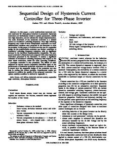
Figures 3 and 4 show I-V and P-V characteristics of two numbers of 37Wp Solar panels in series for different solar radiations and figures 5 and 6 show the same in Parallel connection using PSpice 9.1 software
Fig. 6:-P-V characteristcis of two numbers of 37Wp solar panels connected in parallel using PSpice 9.1 software
Fig. 3:-I-V characteristcis of two numbers of 37Wp solar panels connected in series using PSpice 9.1 software
B. Zero Current Switching Buck Converter Fig.7 shows the circuit diagram of ZCS buck Converter. Fig 8 shows its simplified diagram with various parameters of
voltage and current marked on it. The ZCS buck converter circuit consists of a main switch and an auxiliary switch along with a resonant inductor and capacitor. At the output side, there is an L-C low pass filter.
Taking higher value, Maximum Output Current = 15A. The equivalent output impedance, =
Vo 15 = = 1Ω , Q=1, I o 15
(2)
Hence characteristic Impedance,
Ro = 1Ω , Q
Zo =
(3)
Assume the normalized switching frequency,
f ns = 0.7
The necessary resonant frequency is derived from
f s 16 KHz = = 22.85KHz f ns 0.7
fo =
(4)
Resonant Angular Frequency, Fig.7:-Circuit diagram of ZCS Buck Converter
1 = 143.57 ×10 3 rad / s Lr × C r
ω0 =
(5)
Resonant Inductor is,
Lr = Z 0 ω0 =
1 = 6.96 μH 143.57 × 10 3 rad / s (6)
Resonant Capacitor is,
Cr = Fig. 8:-Simplied diagram of ZCS Buck Converter
Fig.9 shows theoretical waveforms of various parameters. As shown in the waveforms, the main switch and auxiliary switch follow the Zero Current switching condition with zero power loss during switching.
1 1 = = 6.96 μF ω 0 × Z 0 143.57 × 10 3 rad / s
(7) To limit charging current ripple and the output voltage ripple ,the circuit parameters for the low pass filter of the ZCS battery charger are set as follows, L0 = 100 × Lr = 696μH (8)
C0 = 100 × C r = 696 μF
(9)
The calculated circuit parameters are as follows in Table I TABLE I. Solar panel Input Voltage,
37 + 75 = 112W p 17.5V
Vi
Switch Frequency,
The designed components values are calculated as follows, Assume Input Voltage from Solar Panel at MPP=17.5V (approx.), Output voltage required for battery charging=15V (approx), Assume Switching Frequency, f s = 16kHz Capacity of Solar Panels= 37Wp Maximum Charging Current
=
+ 75W p = 112W p
112 = 10 A( Approx.) 12
16kHz
fs
Resonant Frequency,
Fig.9:-Theoretical Waveforms of ZCS Buck Converter
CIRCUIT PARAMETERS
f0
22.85kHz
Output voltage, V0
15V
Lr Resonant Capacitor, C r Filter Inductor, L0
6.96 μH 6.96 μF 696 μH
Resonant inductor,
Filter Capacitor,
C0
696 μF
Main switch
MOSFET IRF 250
Auxiliary switch
MOSFET IRF 250
Fig.12:-Gate Switching signals Vg (Main Switch) and signals (Auxiliary Resonant Switch) Vga
Fig.10.Circuit diagram of the Solar charge Controller
Fig. 10 shows the circuit diagram of Solar charge Controller with ZCS Buck Converter. Fig. 11 shows the MOSFET driver circuit with TLP 250. Fig.13:-Data of Gate Switching signals Vg (Main Switch) and signals (Auxiliary Resonant Switch) Vga
Fig.11:- MOSFET driver circuit using TLP 250
Figures 12 to 20 show experimental waveforms of different parameters of ZCS buck converter on Caddo 9100 Make DSO. For generating the current waveforms, a 1 Ω resistor was connected in series of the required component and the voltage waveform was generated across it to get the current waveform. In fig. 13, the DSO current probe setting was used with a multiplier of 100, hence it is showing the voltage level above 100V. This voltage should be divided by 100 to get actual voltage levels.
Fig.14.Current across Resonant Inductor (ILr)
Fig.15.Data of Current across Resonant Inductor (ILr)
Fig.16.Voltage across freewheeling diode (VDm)
Fig.20.Data of Current across freewheeling diode (IDm)
C.
Fig.17.Data of Voltage across freewheeling diode (VDm)
Constant Current Charge Controller Fig. 21 shows the simulated circuit diagram of the constant current Charge controller which is connected at the output of ZCS buck converter. Multisim 10.0 is used for simulation of Constant Current Charge Controller. Potentiometer R4 is used for setting the overcharge voltage setting and potentiometer R3 is used for undercharge alarm. Potentiometer R14 is used to set the charging current of the battery. Optocoupler IC MCT-2E controls the switching of the MOSFET IRF 540 to start the charging of the battery 12V, 45Ah. The various levels of the voltages set using potentiometers are also shown in Fig.21.
Fig.18.Voltage across Resonant capacitor (Vcr)
Fig.21.Constant Current Charge Controller with charging control levels set using potentiometers
Fig.19.Current across freewheeling diode (IDm)
Fig. 22 shows the curve of efficiency Vs output power for ZCS Buck Converter under varying load conditions. A Rheostat of 200Ω/ 15A is used as a load for getting the results. Fig. 23 shows charging efficiency of 12V, 45Ah lead acid battery.
[6]
[7]
[8]
Fig.22.Efficiency Vs Output power
Fig.23.Charging efficiency
III.
CONCLUSIONS
The Solar charge controller is designed using ZCS buck converter topology. In this topology, it is ensured that PWM generation through microcontroller ATmega16 will be controlled depending upon solar radiation, intensity and temperature. Future work is aimed at implementing modified perturb and observe method in the Solar Charge Controller for Maximum Power Point Tracking (MPPT) control. ACKNOWLEDGMENT The authors are thankful to the Management authorities of St. Vincent Pallotti College of Engg. And Technology, Nagpur, Maharashtra, INDIA and Visveswaraya National Institute of Technology, Nagpur, Maharashtra, India for providing the facilities to carry out the research work in the laboratories. REFERENCES [1]
[2]
[3]
[4]
[5]
H.Masheleni and X.F. Carelse, “Microcontroller-Based Charge Controller for Stand-Alone Photovoltaic System”, IEEE Transactions on Solar Energy, 1997 vol.61, No.4, pp. 225-230,. X. Long, R. Liao and J. Zhou1 “Low-cost charge collector of photovoltaic power conditioning system based dynamic DC/DC topology” IET Renew. Power Gener., 2011, Vol. 5, Iss. 2, pp. 167–174. Siwakoti, Y.Prasad, Bhupendra Bimal Chhetri, Brijesh Adhikary and Diwakar Bista, "Microcontroller Based Intelligent DC-DC Converter to Track Maximum Power Point for Solar Photovoltaic Module”, IEEE conference, 2010 pp 94-101 Y.Chun Chuang, “High-Efficiency ZCS Buck Converter for Rechargeable Batteries”, IEEE Transaction of Industrial Electronics, July 2010,Vol. 57, No. 7,. Y. Chuang and Y.Lung Ke, "A Novel HighEfficiency Battery Charger with a Buck Zero-Voltage-Switching Resonant Converter" IEEE Transaction on energy conversion, December 2007,Vol.22, No. 4,
[9]
S. Pattnaik, A. K. Panda, and K. Mahapatra"Efficiency Improvement of Synchronous Buck Converter by Passive Auxiliary Circuit" IEEE Transaction on Industrial Applications, November/December 2010 Vol. 46, NO. 6, B. P. Divakar and Danny Sutanto" Optimum Buck Converter with a Single Switch" IEEE Transaction on power Electronics, July 1999. Vol.14, No.4, A.S.Werulkar and P.S.Kulkarni,”Analysis of Microcontroller based Solar Charge Controller for Solar Home Lighting System”. Proceedings of International Conference on Advances in Energy Research (ICAER2011) IIT, Bombay, India, December 9-11, 2011. R.S.Sable,A.S.Werulkar and P.S.Kulkarni,” Microcontroller Based Soft Switching Buck Converter for Solar Home Lighting System” Proceeding of National Conference on Emerging Technologies, Renewable Energy & Electrical Engineering, ITM, Bhilwara,India"ETREEE – 2012 February 25-26, 2012, pp 166-173.