An Improved Method for Water Blotches Detection and Restoration ∗ IPL
† LCI
F. Stanco∗ , L. Tenze∗ , and A. De Rosa† - DEEI, University of Trieste, Via A. Valerio, 10 - 34100 Trieste, Italy - DET, University of Florence, Via S. Marta, 3 - 50139 Florence, Italy
[email protected],
[email protected],
[email protected]
Abstract— In this paper an algorithm to digitally restore vintage photographic prints affected by water blotches is proposed. The algorithm uses a new simple and effective semiautomatic detection, and a smart restoration method based on an additive/multiplicative model. The obtained results show that these defects are completely removed without producing significant artifacts. Index Terms - Interpolation, Restoration, Water blotches.
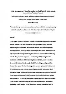
I. I NTRODUCTION Vintage photographic prints are often conserved in adverse environments, at least for a part of their life. One of the most aggressive and, at the same time, frequent menaces come from water, which can permeate portions of the paper and produce very visible stains on the picture. The result is the so called water blotch (Fig. 1), which is often characterized by having a vaguely round shape, a color darker than the neighborhood due to the dust which is attracted in the paper texture, and an even darker border where the dust accumulates. An important peculiarity of this type of damage, which differentiates it from the many other defects which a print can show, is that the blotch does not completely destroy the content of the picture in the affected area: such a region is darker, but the image details are still visible, at least partially. The physical restoration of
Web sites. For this type of application, we propose in this paper a method for the virtual, semi-automatic restoration of the digital version of the print. Virtual restoration has been proposed in many cases [1], [2], [3], [5], [4], [12], [14], [17], [18], and proved to be convenient for various reasons: the processing is reversible and the original print is not affected, so that novel restoration techniques can be attempted without risks; moreover, the restoration process can be at least partially automated, and this permits to treat a huge amount of samples in a short time, without engaging dedicated personnel; finally, the cost of the process is small, so that any professional photographer or small museum can afford it. Techniques for effectively eliminating water blotches are however still needed. In [6] a method is presented which restores photographic prints affected by water blotches, but the detection was performed manually. A pixel in the stain was manually selected and all the neighbor pixels, whose gray level was close to the selected one, were labeled as part of the blotch. This procedure needs a very high number of iterations to obtain good results and the final accuracy is affected by subjective factors. In this paper, we pay specific attention to the detection phase of the process. Based on the peculiarities of the defect which have been mentioned above, we propose a new method that gives good results in few iterations. Moreover, the method proposed in [6] performs a restoration that does not consider the color range in the area to restore. The extraction of the algorithm parameters in areas with high colors variance could create visible artifacts. In this paper we propose an improvement of the restoration step to avoid this kind of problems. The rest of the paper is organized as follows: Section II describes the additive multiplicative model; Section III describes the algorithm; Section IV shows the experimental results. A conclusions section ends the paper. II. T HE ADDITIVE / MULTIPLICATIVE MODEL
(a) Fig. 1.
(b) (a) and (b) two examples of water blotches
the print is a time-consuming and delicate operation, which requires skilled personnel. Often however the original print is scanned or acquired with digital photographic equipment, also to be able to exploit it in virtual museums and commercial
The restoration algorithm used in this paper is based on an additive-multiplicative model. As mentioned in [6], a suitable model to describe the corrupted region Ω of the image I can be the following: I(Ω) = α ∗ J(Ω) + β
(1)
where J is the uncorrupted version of I, α and β are the parameters to be estimated.
If the variance and the mean (respectively denoted as var[.] and M [.]) are applied to the Eq. 1, we obtain: ½ var[I(Ω)] = α2 ∗ var[J(Ω)] (2) M [I(Ω)] = α ∗ M [J(Ω)] + β The previous equation can be used to estimate the α and β values. However, the variance and the average of the uncorrupted image J are unknown. In order to solve Eq. 1, e where Ω e is an uncorrupted we approximate J(Ω) with I(Ω), area around the blotch (Fig. 4(a)). Therefore the approximate values of α and β can be obtained by solving the equation system in 2. Each pixel of the wrong regions can be corrected as follows: e α. e J(Ω) = (I(Ω) − β)/e
(b)
Fig. 2. (a) In white are reported all the pixels processed with a simple interpolation across the edge; (b) the pixels processed after the last interpolation)
III. R ESTORATION OF WATER BLOTCHES (3)
where Je is the restored image. After this step the area inside the blotch is restored and it appears free of artifacts. However, the contour of the stain could still be apparent. This effect is strictly related to the model described above and can be reduced by using the interpolation step proposed in the next subsection. Interpolation A linear interpolation close to the border is performed to restore the water blotches: the luminance gradient is evaluated for each pixel pi in the contour. Then, an array {pk : i − L ≤ k ≤ i + L} of 2L + 1 pixels centered in pi is considered: the data are chosen along the gradient direction in pi so that L samples belong to the corrupted region and L belong to the uncorrupted one. If we denote with Pstart the first pixel of the array and with Pend the last one, a linear interpolation can be performed according to the distance between the pixels. If Pj −P end d(Pj ) = Pstart −pend is the normalized distance of each pixel in the array from the Pstart position, the new intensity values are: e j ) = d(Pj ) ∗ J(P e start ) + (1 − d(Pj )) ∗ J(P e end ) J(P
(a)
(4)
It has to be noticed that the new values in the vector depend only on the intensities in Pstart and Pend , and the original values are not considered. The white pixels in Fig. 2(a) show the samples processed during this interpolation step. It has to be noted that the white strip in Fig. 2(a) is not continuous due to the fact that the gradient orientation can be very different even for neighbouring pixels and some samples can remain unprocessed. Therefore, we search all the unchanged pixels in a border strip of width 2L + 1, and we assign a gray level value to each pixel corresponding to the average of its already interpolated neighbors in a 3 × 3 mask. With the last interpolation step the unmarked pixels are processed, so that the strip is now continuous (Fig. 2(b)) and the artifacts are reduced. To apply the method explained in this section, we have supposed to exactly know the blotch area Ω and e of the input image I 0 . How these the undamaged region Ω parameters are determined will be explained in the following section.
To restore water blotches we consider the digital image I. First we convert the image I into a graylevel color space in order to properly detect the wrong regions of the original data. The detection phase is based on the assumption that the blotch profile is darker than the rest of the blotch. The user manually selects one pixel within the blotch. We label all the pixels whose neighborhood are not in the outline as belonging to the stain. The restoration phase exploits the additive/multiplicative model described in the previous section and automatically estimates the parameters. If the blotched region covers an area with significant details, the method divides this area into two blocks in order to avoid artifacts. Detection As mentioned in the Introduction, specific algorithms for the detection of water blotches do not exist in the scientific literature. The methods presented in [8], [10], [11], [13], [15], [16], [17], [18], can not be applied to water blotches due to the fact that there are no simple rules to correctly identify the corrupted regions. In [7], [9] a similar problem is treated by considering that the damage is darker than the background and is characterized by approximately uniform gray levels. The classification is performed by optimizing a function based on the luminance uniformity and on the magnitude of the gradient values in that region. Going into details, a pixel is labeled as belonging to a damaged area if the new area, obtained adding this pixel to the damaged area, increases the value of a suitable function. Despite the accuracy of the results in locating cracks or gaps in artworks, these algorithms do not provide good results with water blotches, because the blotch is not characterized by a uniform gray level and the real data of the image are not completely lost within the blotch region. In [6] the used detection method needs a strong user intervention. This is based on the consecutive selection of pixels in the blotch area by the user. All these pixels and all the neighbor pixels with gray level close to the selected one are labeled as belonging to the stain. In this paper we propose a new semi-automatic algorithm to detect all the pixels in the blotches. This method needs that the user manually selects just one point in the damaged area, and the remaining region of the damage is automatically detected.
The point suggested by the user indicates only the position of the blotch and does not represent a reference to which other pixels are compared. The process does not depend on the chosen starting point and the same results can be obtained using another starting point within the blotch. The detection works over a graylevel image. If the input image I is a color image, we consider as input of the detection algorithm the image I 0 , the graylevel version of I. We perform a simple preprocessing step to improve the contrast of the image I 0 and, in particular, to enhance the edge of the blotch. This process is particularly helpful in the following steps of the algorithm because the images with low contrast can produce wrong edge detection. The contrast improvement is achieved using a common technique for contrast enhancement, based on the graylevel morphological filtering. 0 We define the top-hat transform Itop as the difference between the original image and its opening. In a similar way 0 the bottom-hat transform Ibot is defined as the difference between the closing of the original image and the original image itself. The top-hat image contains the ”peaks” of objects that fit the structuring element; the bottom-hat image shows the gaps between the objects of interest. To maximize the contrast between the objects and the gaps that separate them from each other, the ”bottom-hat” image is hence subtracted from the ”original + top-hat” image: 0 0 0 Inew = (Itop + I 0 ) − Ibot
(5)
0 Using an edge detector we calculate the gradient of Inew . We suggest to use the Canny algorithm to find the edges because this operator provides good results in detecting the edges and it is very robust to the noise. 0 0 Icanny = Canny edge detector(Inew ) 0 Ibin1
(6)
0 Ibin2
We create two binary images and by thresholding 0 the image Icanny . We use two user-defined thresholds T h1 0 0 and T h2 , over Ibin1 and Ibin2 , respectively. The thresholds should be different, the first one relatively high and the last 0 one lower. The image Ibin1 is a map with the steepest edges 0 (Fig. III); while Ibin2 includes the smoother edges.
Fig. 3.
0 The binary image Ibin1 of Fig. 1(a)
Starting from the point selected by the user, the algorithm analyses the surrounding area using a 3 × 3 window to extend the detection map: the samples within the window which do not belong to the border, are labeled as ”damaged”. This process is iteratively repeated over the new detected pixels,
until there are pixels ”unexplored”. The map of all the pixels labeled as belonging to the blotch is stored into the matrix Idet . When the procedure ends, a morphological closing is applied on Idet , in order to remove the little gaps within the detection area. If the previous stage does not provide an exhaustive detection, the user can select a new point and the procedure can be repeated to improve the previous detection. In this case the 0 binary image Ibin2 , which contains more details, is taken into account for the detection. This selection/labeling procedure is repeated until all the pixels in the blotch are selected. At the end of the detection procedure, the image Idet is a map containing the positions of the damaged pixels. Restoration The algorithm proposed in [6] to remove water blotches exploits the additive/multiplicative model presented in Section II. Values for the model parameters are automatically extracted e If Ω is the by examining a suitable area around the blotch Ω. blotch to be restored, we automatically extract the area around e with width W . To avoid using pixels that are too the blotch Ω e is determined close to the blotch, and hence are unreliable, Ω as shifted by S pixels away from the contour. This shift ensures that an erroneous detection of the border does not affect the accuracy of the final result. As mentioned above, the procedure presented in this paper takes into account that the water blotch could lie on a non homogeneous region with high variance (Fig. 1(b)). This means that the blotched region covers an area with significant details. In this case the method divides this area into two blocks in order to avoid the artifacts. Obviously, if the blotch e will be split. Ω is split in two regions, also the area Ω This separation is performed considering the minimum and e maximum of the region. More precisely, to divide the area Ω e e e e in Ω1 and Ω2 , we compare each pixel in Ω with min(Ω) and e and put the pixel in the set which is more close to. max(Ω), Similarly, the water blotch Ω is split in Ωa and Ωb . Now, we e 1 with the either Ωa or Ωb ; and Ω e 2 with the remaining. pair Ω The idea is that the areas to be coupled have to be similar; and similar areas have close median values. This means that our procedure compares the median values and couples the areas only if the median is similar (Fig. 4(b)). If there is no e and Ω. similarity, we use only Ω The final interpolation after the additive-multiplicative model does not take into account pixels that belong to the other part of the spot and its related undamaged area. For example, e 1 , the procedure will if the blotch area Ωa is associated with Ω e not use the pixels in Ωb and in Ω2 . Moreover, we notice that, e is not divided because the variance in the area is low, we if Ω apply the additive/multiplicative model on the whole stain and the α and β parameters are extracted taking into account the whole area around the blotch. IV. E XPERIMENTAL R ESULTS This section shows some results obtained applying the algorithm to old photographic prints. The algorithm parameters
V. C ONCLUSIONS AND FUTURE WORK
(a)
(b)
e (black); (b) Ω Fig. 4. (a) Damaged area Ω (white) and undamaged area Ω e are split and the corresponding areas have the same color. and Ω
have been chosen taking into account the tests results. The thresholds T h1 and T h2 are set equal to 0.45 and 0.02, respectively; the distance S between the water blotch and the uncorrupted area is chosen equal to 7; the width W e ∗ is 10; and L=3 in the interpolation stage, after the of Ω additive/multiplicative model. Fig. 5 reports some processed images. It should be noted that the proposed algorithm has been tested with uncompressed and compressed images, in Tiff and Jpeg format respectively. In all the cases the algorithm provided good results. The performances of the algorithm cannot be quantitatively estimated due to the fact that the images are originally affected by water blotches: therefore it is not possible to compare the performances via MSE or PSNR. It is possible to notice that
(a)
(b)
Fig. 5. (a) Image in Fig. 1(a) after restoration; (b) Image in Fig. 1(b) after restoration
the algorithm enhances the information in the blotch and does not replace it with a texture or with new gray levels values different from the original ones. This behaviour allows to restore large damaged areas while preserving the details and without introducing artifacts. In particular the images in Fig. 5(b) have details that have been preserved eliminating only the water drop effect.
In this paper a new algorithm to restore water blotches from vintage photographic prints has been proposed. This method consists of a simple and semi-automatic detection and a restoration procedure which produces good results even in presence of strong details. The experimental results show that the stains are removed without any visible artifacts enhancing the residual information in the area. In order to further reduce the remains of the water blotch after the restoration, we are testing a quadratic additive/multiplicative model and a non linear interpolation algorithm to eliminate the artifacts within the contour. VI. ACKNOWLEDGEMENTS A special thanks to Prof. G. Ramponi for his support and his useful hints. We thank F.lli Alinari s.p.a. for providing all the pictures used in our experiments. This research has been partially supported by a grant of the Regione Friuli Venezia Giulia and by EC Project COST #276, within a Short Term Scientific Mission of the first author at the Comunication and Image Processing Laboratory of the University of Florence, Italy. R EFERENCES [1] F. Stanco, G. Ramponi, A. de Polo, ”Towards the Automated Restoration of Old Photographic Prints: a Survey”, in Proc. IEEE-EUROCON 2003, Ljublijana, Slovenia, September 2003; [2] C. Ballester, M. Bertalmio, V. Caselles, G. Sapiro, J. Verdera, ”Fillingin by Joint Interpolation of Vector Fields and Gray Levels”, IEEE Transactions on Image Processing, vol. 10 (8), pp. 1200- 1211, 2001. [3] M. Bertalmio, G. Sapiro, V. Caselles, C. Ballester, ”Image Inpainting”, in Proc. SIGGRAPH 2000, pp. 417-424, 2000. [4] M.M. Oliveira, B. Bowen, R. McKenna, Y.S. Chang, ”Fast Digital Image Inpainting”, in Proc. International Conference on Visualization, Imaging and Image Processing VIIP 2001, Marbella, Spain, pp. 261-266, 2001. [5] S. Masnou, J.M. Morel, ”Level lines based disocclusion”, in Proc. ICIP 98, pp. 259-263, 1998. [6] F. Stanco, G. Ramponi, L. Tenze, ”Removal of Semi-Transparent Blotches in Old Photographic prints”, in Proc. 5th COST 276 Workshop, Praha, Czech Republic, October 2003; [7] M. Barni, F. Bartolini, V. Cappellini, ”Image Processing for Virtual Restoration of Artworks”, IEEE MultiMedia, 7(2), pp. 34-37, 2000. [8] J. Chen, A.K. Jain, ”A Structural Approach to Identify Defects in Textured Images”, In Proceedings of the IEEE International Conference on Systems, Man, and Cybernetics, pp. 29-32, Beijng, 1988. [9] A. De Rosa, A.M. Bonacchi, V. Cappellini, M. Barni, ”Image Segmentation and Region Filling for Virtual Restoration of Art-Works”, In Proceedings of ICIP 2001, vol. 1. pp. 562-565, 2001. [10] www.asf.com/products/ [11] www.canon.com.sg/index.cfm?fuseaction=scanner&prod type=fare [12] www.polaroid.com/service/software/poladsr/poladsr.html [13] N.D. Kim, S. Udpa, ”Nonlinear Operators for Edge Detection and Line Scratch removal”, In Proceedings of IEEE International Conference on SMC, pp. 4401-4404, 1998. [14] A. Kokaram, Motion Picture Restoration, Springer, 1998. [15] F. Roli, ”Measure of texture anisotropy for crack detection on textured surfaces”, Electronics Letters, 36(14), pp. 1274-1275, 1996. [16] K.Y. Song, M. Petron, J. Kitter, ”Wigner based Crack Detection in Textured Images”, In Fourth IEEE International Conference on Image Processing and its Applications, pp. 315-318, 1992. [17] D. Tegolo, F. Isgr, ”A Genetic Algorithm for Scratch Removal in Static Images”, In Proceedings of ICIAP 2001, pp. 507- 511, 2001. [18] L. Tenze, G. Ramponi, S. Carrato, ”Robust detection and Correction of Blotches in Old Films using Spatio-Temporal Information”, In Proceedings of SPIE Intern. Symp. Electronic Imaging 2002, 2002.