Communications and Network, 2013, 5, 245-248 http://dx.doi.org/10.4236/cn.2013.53B2045 Published Online September 2013 (http://www.scirp.org/journal/cn)
An Improved SPIHT Algorithm for Image Compression in Low Bit Rate Ping Liu, Guanfeng Li School of Physical and Electrical Information Engineering, Ningxia University, Yinchuan, China Email:
[email protected] Received May, 2013
ABSTRACT Aiming at shortage of the SPIHT algorithm, an improved image compression algorithm is proposed, in order to overcome the shortcomings of decoding image quality and coding time, LS9/7 lifting wavelet transform is adopted. According to the characteristics of the human visual system (HVS), the scanning mode and the method to determine the threshold of algorithm are changed to improve the quality of reconstruction image. On the question of repeating scan of SPIHT algorithm, using maximum list thought, greatly reduce the computation and save operating time. The experimental results have proved that the improved algorithm of image decoding time and the quality of reconstruction images are better than the original algorithm , especially in the case of low bit rate. Keywords: Wavelet Transformation; Lifting Scheme; Threshold; Set Partitioning in Hierarchical Trees(SPIHT); Human Visual System(HVS); Image Compression; Low Bit Rate
1. Introduction Wavelet transform has a good locality character of timefrequency domain, overcome the limitations of Fourier transform in dealing with the smooth complex image signal effectively, the sub-image after transformation has strong comparability. It is convenient for coding the subsequent, made the wavelet transform widely used in image compression field. J. M. Shapiro proposed EZW (Embedded Zero-tree Wavelet) [1] algorithm in 1993, the complexity of this algorithm is not high, and the streaming is embedded. It is easy to control compression ratio and realize scalable coding. A. Said and W. A. Pearlman proposed a new efficient improvement method in 1996, namely SPIHT (Set Partitioning In Hierarchical Tree) [2,3], using the spatial direction tree, this method shows wavelet coefficients of zero tree structure efficient and accurate, which increased the compression efficiency and reduced the complexity of the coding. SPIHT algorithm treat the lowest frequency sub-band coefficient the same importance, so when sorting and scanning process using LIP determine the importance of the wavelet coefficients, only a small part of the bits are used for coding important information, especially in low bit rate, it will inevitably lead to the quality of the recovery image descend. Need a lot of storage space, and exists the disadvantage of repeating problem, this paper focused on the problems of SPIHT algorithm and proposed an improved scheme, combined with the human visual characteristics. To reduce the algorithm of middle Copyright © 2013 SciRes.
storage and the time consumption, meanwhile improved the quality of the decoded image in low bit rate.
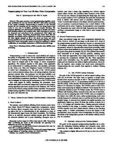
2. Related Algorithm Principle 2.1. Lifting Wavelet Transform Sweldens using lifting format (Lifting Scheme, LS) construct wavelet transform in 1994.The basic idea is by a inertia Wavelet (Lazy Wavelet, LW),and gradually construct a new wavelet [4-6]. Lifting format gives a simple and effective method to construct the biorthogonal wavelet. It use the basic polynomial interpolation to get the signal of the high frequency components, by constructing scale function to get the signal of the low frequency components. This scheme consists of three steps: split, predict and update. Supposed the original signal is x[n], the exchange process of the signal is as shown in Figure 1. s[n] is the low frequency components of x[n], and d[n] is the high frequency components of x[n]. 1) Split: split signal x[n] into two related parts, a[n] and b[n]. Sampling interval according to the parity serial number of data, namely: a[n]=x[2n], b[n]=x[2n+1]. 2) Predict: using the correlation among the data: using a[n] predict b[n].adopt prediction operator P() makes: d[n] = b[n]-P(a[n]). 3) Update: using update operator U() , using d[n] revise x[n], the revised signal x[n] (recorded as c[n]) contains the low frequency part of signal x[n] only, namely: c[n]=a[n]+U(d[n]). CN
P. LIU, G. F. LI
246
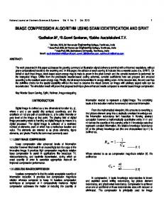
Because 9-7 integral wavelet lifting scheme has good energy concentration, vanishing moment is bigger. So adopt the 9-7 integral wavelet lifting scheme in this article. As shown in Figure 2. Biorthogonal lifting wavelet coefficient can obtain by solving FIR wavelet filters in time domain. Here, gives LS9/7 wavelet coefficient directly: -1.586134342 -0.05298011854 (1) -0.88291107602 -0,4435068522 K 1.149604398 Take the approximate value:
, , , ,K -1/16, -4/5,-15/32, -4 2 /5 ) (-3/2 ,
(2)
2.2. SPIHT Algorithm 1) Partition rules of algorithm The main idea of SPIHT algorithm [2,3] is by reduced progressively threshold sequence generating a series of important diagram (or bitmap) to approximate every wavelet coefficients gradually. For any node (i, j ) bring in four sets as follow: O(i, j ) : The coordinate sets of the four direct subsequent node of (i, j ) ; D(i, j ) : The coordinate sets of all the subsequent node of (i, j ) ; L(i, j ) : The coordinate sets of all the subsequent node except direct subsequent node of (i, j ) namely: L(i, j ) D(i, j ) O(i, j )
H: The top of coordinate sets in decomposition of the wavelet pyramid. For all child nodes except root node of (i, j ) : O(i, j ) {(2i, 2 j ), (2i, 2 j 1), (2i 1, 2 j ), (2i 1, 2 j 1)}
Xe[n]
x[n]
Split
Predict
Xo[n]
—
s[ n ]
Update
d1[ n ]
d [ n]
Figure 1. Decomposition of lifting algorithm. Sj1
2
Z-1 2
Xo[n]
Xe[n]
k
(3)
2) Algorithm description: SPIHT algorithm consists of three linked list to record coding information: LIS: List of Insignificant Sets; LIP: List of Insignificant Pixels; LSP: List of Significant Pixels; a) Initialization Suppose T 2n , n log 2(max (i , j ) c i , j ) , C i , j are
wavelet coefficients, the initial LSP is empty. LIP {(i, j ) | (i, j ) H LIS {D (i, j ) | (i, j ) H } are coordinate sets of all roots. b) Classification scanning This process scanning LIP and LIS only. For each coordinates of LIP, if C i , j T n , record C i , j as the unimportant coefficient, and sign "0". On the contrary sign "1" as important symbol and output the symbol of C i , j , and moved this table from LIP to LSP tail. For unimportant subset LIS, each table corresponding to a wavelet coefficients set Ci , j , if C i , j T n , record Ci , j as important subset, and output important symbol "1", update LIP and LSP. Otherwise, output "0". c) Fine scanning This process scanning LSP only, for each (i, j ) of LSP, if (i, j ) is not a new add in the scanning process has just, according to the current quantitative threshold T n , judging the size of the most significant bit of the wavelet coefficients, and output the nth important bit of C i , j in binary. d) Update the threshold Order n = n + 1 and quantized threshold as T n+1 = T n for the next scanning. For LIP, LSP and LIS use the same rules to update.
2.3. Improved SPIHT Algorithm
dj
According to the human visual characteristics, the sensitivity of the human for the high frequency information is far less than the low frequency, therefore do the following treatment: weighted each sub-band coefficient as in [7-9] which shown in Table 1, multiplied by each coeffi-
Figure 2. 9-7 integral lifting wavelet scheme. Copyright © 2013 SciRes.
1, max{ C (i, j ) } 2n ( i , j ) (i , j )T Sn 0,others
Sj
1/k
a) The initial segmented set consists of (i, j ) and D (i, j ) , D (i, j ) H . b) If D(i, j ) is important, split it into L(i, j ) and four single element sets. (k , l ) (i, j ) . c) If L(i, j ) is important, split it into four sets D (i, j ) , (k , l ) O(i, j ) . The basic operations of SPIHT algorithm are set test, it description as follows:
CN
P. LIU, G. F. LI
cient when coding and divided by it while decoding. 1) Adopt different threshold for the different low frequency and high frequency sub-band, LL layer are different from the other three layers, so the lowest frequency sub-band and other three bit allocation adaptive when coding, make the output streaming distribution more bits to the low-frequency coefficients. So, it will gain higher signal-to-noise ratio (SNR) in the same bit rate situation. In the case of the same SNR, due to improve detailing the threshold, the system exist more zerotree. It can reduce the coding time computation effectively. 2) Improvement of the low frequency sub-band After processing as step 1), to the lowest layer coefficient LLN of the nth decomposition, output priority as fine scanning streaming, it will receive this information the first while decoding, according to this message restore the scanning process and decoding. Using this op- timization measures to ensure that transmit important visual coefficient priority, also is the standard of the fre- quency for priority, the low frequency information should be transmit prior than high frequency, and when two principles (frequency priority and absolute value priority) conflict, consider frequency priority at first. Improved the quality of reconstruction image in low bit rate. 3) Improvement of the high frequency sub-band For the other three high frequency sub-band as in [1012], using maximum list thought as follows: establish maximum linked list MAX in the initial process, store the maximum coefficient of corresponding elements node of LIS, if maximum number exceeds the threshold, then scanning corresponding coefficient position of LIS, otherwise, don’t consider the current threshold. In the later process, will compare the threshold and maximum value only, do not need to compare one by one, and thereby reducing the large amount of calculation. Improved algorithm initialization as the formulation given in (4)
C C C
i , j i , j i , j
3. Results and Analysis 3.1. The Influence of Test Performance in Different Decomposition Layers and Coding Level (256 * 256 * 8 bit Lena Images) Table 2 shows the experimental data of improved algorithm of different decomposition layers and coding level. By experiment we find that the best result are three layers of wavelet decomposition and eight level coding.
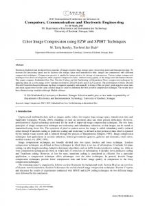
3.2. The Comparison of the Basic Algorithm and the Improved Algorithm in This Paper Table 3 shows the comparison of the basic algorithm and the improved algorithm. In this experiment, Take 512 * 512 * 8 bit Lena as the test image when in the case of three layers of wavelet decomposition and eight level coding. By experimental, we found that the SNR are improved of the improved algorithm, It is more apparent especially in low bit rate, at the time the coding time faster 0.1s to 0.3s or so than the basic algorithm. Figures 3(a), (b), and (c) are reconstruction images for the original image, the basic algorithm and improved algorithm in the bit rate of 0.0625 respectively, (d) is the image of three layers of wavelet decomposition and eight level coding, through observation subjective, we found that the improved algorithm of image decoding time and the quality of reconstruction images are better than the original algorithm, especially in the case of low bit rate. Table 2. The experimental data of improved algorithm of different decomposition layers and coding level. decomposition layer 3
n _ m ax1 = log 2 m ax( i, j) C LL i , j n _ m ax2 = log 2 m ax( i, j) n _ m ax3 = log 2 m ax( i, j) n _ m ax4 = log 2 m ax( i, j) n = n _ m ax1
HL
LH
HH
4
(4)
Table 1. Weighted coefficient of each sub-band.
HVW
1
Sub-band HL3 HVW
LH5
HL5
HH5
LH4
HL4
HH4
LH3
0.798 0.798 0.684 0.962 0.962 0.849 0.981 HH3
LH2
HL2
HH2
LH1
HL1
HH1
0.981 0.938 0.843 0.843 0.516 0.362 0.362 0.082
Copyright © 2013 SciRes.
5
coding level
PSNR(db)
6 7 8 6 7 8 6 7 8
37.1115 42.8990 50.4635 36.1419 41.9839 49.3562 35.364 41.3681 48.7538
Table 3. The comparison of the basic algorithm and the improved algorithm.
n _ m ax = m ax(n _ m ax2,n _ m ax3,n _ m ax4)
Sub-band LL5
247
Bit rate (bpp)
Improved algorithm PSNR (db)
Basic algorithm
coding decoding PSNR time(s) time(s) (db)
coding decoding time(s) time (s)
0.015625
25.435
0.140
0.016
17.320
0.140
0.063
0.03125
26.876
0.187
0.031
21.668
0.321
0.092
0.0625
30.704
0.328
0.062
28.390
0.650
0.120
0.125
32.997
0.547
0.125
31.100
0.910
0.180
0.25
35.580
0.906
0.269
34.110
1.260
0.270
0.5
37.460
1.563
0.465
37.210
1.670
0.480
CN
P. LIU, G. F. LI
248
(a) Original image
[2]
ANTONINI Metal, “Image Coding Using Wavelet Transform,” IEEE Transactions on Image Processing, Vol. 1, 1992, pp. 205-2203. doi:10.1109/83.136597
[3]
A. Said and W. Pearlman, “A New Fast and Efficient Image Codec Based on Set Partitioning in Hierarchical Tress,” IEEE Transactions on Circuit and System for Video Technology, Vol. 6, 1996, pp. 243-250.
[4]
Sweldens. W, “The lifting scheme: a custom-design construction of biorthogonal wavelets,” Applied and Computional Harmonic Analysis, Vol. 6, No. 2, 1996, pp. 186-200. doi:10.1006/acha.1996.0015
[5]
W. B. Fan, J. Chen and J. N. Zhen, “SPIHT Algorithm Based on Fast Lifting Wavelet Transform in Image Compression,” LNAI, Vol. 2, 2005, pp. 838-844.
[6]
Y. F. Yang and Z. X. Su, “An Improved Based on Wavelet Zerotree Image Coding Algorithm,” China journal of Image and Graphics, Vol. 6, 2001, pp. 542-546.
[7]
L. Y. Li, C. L. Zhan and L. Huang, “The Algorithm of SPIHT Coding Based on LS9/7 Lifting Wavelet,” Communication Technology, Vol. 40, 2007, pp. 362-363.
[8]
P. Yu, X. H. Ma and J. G. Li, “The Algorithm of Image Compression Based on LS9/7 Lifting Wavelet,” Microelectronics and Computer, Vol. 40, 2008, pp. 110-111.
[9]
Z. G. Pan and X. Gao, “Improved SPIHT of Image Compression Algorithm for Texture,” The Chinese Academy of Sciences of Graduate School, Vol. 27, 2010, pp. 222-227.
(b) Basic algorithm (c)Improved algorithm
(d) The image of three layers of wavelet decomposition and eight level coding
Figure 3. The comparison of simulation results.
4. Conclusions According to the shortage of the SPIHT algorithm, it proposes an improved image compression algorithm, using LS9/7 lifting wavelet transform, improved the operation speed and reduce the complexity of the calculation. According to the characteristics of the HVS, the scanning mode and the method to determine the threshold of algorithm are changed, which greatly reduced the computation time. The experimental results have proved that the improved algorithm of image decoding time and the quality of reconstruction images are better than the original algorithm, especially in the case of low bit rate.
5. Acknowledgements We would like to thank the Education Department of the Ningxia Hui Autonomous Region, China for financially supporting this research project under the grant NGY2012024.
REFERENCES [1]
J. M. Shapiro, “Embedded Image Coding Using Zerotree of Wavelet Coefficients,” IEEE Transactions on Signal Processing, Vol. 41, No. 12, 1993, pp. 3445-3462. doi:10.1109/78.258085
Copyright © 2013 SciRes.
[10] Q. Gong and H. Ruan, “The Improved SPIHT Algorithm of Image Compression Based on Integer Lifting Wavelet Transform,” Computer Simulation, Vol. 26, 2009, pp. 195-197. [11] K. Wang, J. W. Zhang, L. L. Wu and Q. Ge, “An Improved SPIHT Algorithm of Image Compression Based on Human Visual System,” Computer Application and Software, Vol. 27, No. 2, 2010, pp. 277-279. [12] B. Yan and H. Zhang, “SPIHT Algorithm and Its Improvement,” Computer Application and Software, Vol. 25, No. 8, 2008, pp. 245-247. [13] H. Q. Su, M. Lv and F. Tan, “Research and Improvement of Image Coding Algorithm,” Journal of Xihua University of Natural Science, Vol. 28, No. 6, 2009, pp. 51-54. [14] Y. B. Qi and G. X. Chen, “An Image Compression Algorithm Based on SPIHT Algorithm,” Journal of Guilin University of Electronic Technology, Vol. 30, No. 4, 2010, pp. 313-315. [15] C. W. Deng, B. J. Zhao, “A Approach to Modify Fast SPIHT Algorithm,” Transations of Beijing Institute of Technology, Vol. 30, No. 4, 2010, pp. 478-482, 2010.
CN