ing test cost by lowering the test data bits and the number of clock cycles .... integer n less than or equal to the number of flip-flops in the circuit, N. The best ...
An Incremental Algorithm for Test Generation in Illinois Scan Architecture Based Designs ∗ Amit R. Pandey† and Janak H. Patel Center for Reliable & High-Performance Computing 1308 W Main Street University of Illinois, Urbana, IL 61801 {apandey, patel}@crhc.uiuc.edu Abstract As the complexity of VLSI circuits is increasing due to the exponential rise in transistor count per chip, testing cost is becoming an important factor in the overall integrated circuit (IC) manufacturing cost. This paper addresses the issue of decreasing test cost by lowering the test data bits and the number of clock cycles required to test a chip. We propose a new incremental algorithm for generating tests for Illinois Scan Architecture (ILS) based designs and provide analysis of test data and test time reduction. This algorithm is very efficient in generating tests for a number of ILS designs in order to find the most optimal configuration.
1. Introduction Testing cost is becoming an important factor in the overall integrated circuit (IC) manufacturing cost due to the exponential increase in transistor count per chip as predicted by Moore’s Law. Transistor feature sizes on a VLSI chip reduce roughly by 10.5% per year, resulting in a transistor density increase of approximately 22.1% every year. Also an equal amount of increase is usually provided by wafer and chip size increases as well as circuit design and process innovations [1]. This increases the complexity of test and increases the testing costs incurred by test pattern generation and test application process. With the increasing complexity of circuits today, the automatic test equipment (ATE) needed to test these circuits is getting more costly. The cost of such ATE rises at the rate of thousands of dollars per pin [2]. In this thesis, we address the issue of decreasing test cost by lowering the test data bits and the number of clock cycles required to test a chip. ∗ This research was supported by the Semiconductor Research Corporation under contract SRC 99-TJ-717. † Currently with Advanced Micro Devices, Inc., Sunnyvale, CA.
A structured test technique like the full scan is widely used in the industry to achieve high coverage and to reduce the complexity of test generation by making all memory elements in the circuit both controllable and observable through a scan chain. The full scan technique involves controlling (observing) the memory elements by serially shifting in (out) the values to (from) the flip-flops. This serial access mechanism increases the test application time. Many improvements to the test application time for full scan circuits have been suggested in the literature. Hybrid test generation schemes [3, 4, 5] are computationally expensive and is not applicable in case of large sequential circuits. The parallel loading technique through parallel direct access to all scan inputs and outputs [6] greatly reduces test application time, but is impractical due to high hardware overhead. Other techniques involve using multiple scan chains [7, 4] done by dividing the scan chain into multiple partitions and shifting each test vector in parallel. This requires additional input/output pins or the use of multiplexers, which degrades the performance of the circuit. A method suggesting the reordering of memory elements in a scan chain can reduce the test application time to some extent [8]. Similarly, several test data volume reduction techniques have also been suggested in the literature. A recently introduced technique utilizes a hybrid of automatic test pattern generation (ATPG) and built-in-self-test (BIST) to reduce data volume [9]. Another technique involves hybrid BIST based on weighted pseudo-random testing [10]. A technique based on compression/decompression using virtual scan chain has also been suggested [11]. Most of these techniques suggested in the literature do not address the needs for embedded cores used in system-on-chip (SOC) designs [12]. Some of the work applicable to SOC designs involves the use of sophisticated compression schemes [13]. Therefore, a new architecture called the Illinois Scan Architecture (ILS) was recently proposed to accommodate the needs of embedded cores [14]. ILS is applicable to both standalone chips or
Serial Scan Mode
chips used as embedded cores. When used in cores, this scheme is attractive because it does not require any additional test pins other than the ones used in scan. So far there has not been any thorough research involving ILS designs and techniques to improve ILS. In this paper, we propose a new incremental algorithm for generating tests for ILS designs. This incremental algorithm is very time efficient and can generate tests for several ILS configurations in a single run.
Scan in
Scan Chain
Scan out
Broadcast Scan Mode Scan in
Scan out
Segment 1 MISR
Segment 2 Segment 3 Segment 4
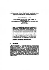
Figure 1. Two Modes of Illinois Scan Architecture
2 Introduction to Illinois Scan Architecture
mode of ILS. Since the broadcast mode imposes logic constraints on test patterns, many faults become untestable. To cover these untestable faults, ATPG is again used, but this time under the serial scan mode of ILS. The additional serial scan vectors cover the testable faults that were rendered untestable under broadcast mode. Illinois Scan based designs are very effective in reducing both the test application time and test data volume [14]. In addition, a case study of industrial circuits has also shown the effectiveness of Illinois scan architecture [17]. In implementing a design based on ILS, one of the preliminary steps involved is deciding upon the number of scan chain segments to be used. It is, however, difficult to predict an ILS configuration that gives the best improvement in test time and volume without any experimentation. Running test generation independently on various ILS configurations becomes quite time consuming when the number of such configurations is large. Therefore, we propose a new incremental algorithm for test generation in ILS based designs, which evaluates several different ILS organizations in a short time.
The Illinois Scan Architecture (ILS) was first introduced in [14]. An overview of this architecture will be provided here. The ILS consists of two modes of operation. The first mode is called the broadcast mode and the second mode is called the serial mode. Figure 1 diagrammatically represents this architecture. The top portion of this figure shows a normal scan chain in the serial scan mode while the bottom shows the broadcast scan mode. The ILS technique divides a scan chain into multiple segments and shifts in the same vector to each of the parallel scan chains through a single scan-in input. For example, in case of a scan chain of length 100 that would be split into four parallel chains, the flops 1, 26, 51, and 76 would be positioned such that they would receive identical scan-in data. Similarly, flops 2, 27, 52, and 77 would also receive identical scan-in data. This shared scan-in idea is similar to an earlier work where a single input was used to support multiple scan chains [15]. However, its application is limited to testing multiple independent full scan circuits in parallel. In ILS, the outputs of the scan chains are compressed into a multiple input signature analyzer (MISR). This is similar to the signature calculation mechanism in a full logic BIST implementation such as STUMPS [16]. Due to the use of a MISR, violation of certain design rules must be avoided. Such rules are avoiding unknown states, internal bus conflicts, and other violations that can corrupt the signature. The implementation of ILS does not require any additional test access pins other than the ones used in full scan technique, i.e., scan in, scan out, and test enable pins. The additional logic required to implement ILS consists of several multiplexers used to switch between two modes of operation and some control logic. The area overhead of these logic blocks is typically quite small compared to the overall chip area.
3 Incremental Algorithm for Test Generation In this section, we first provide theoretical background that is essential to understanding the incremental algorithm for test generation and then present the algorithm.
3.1 ILS-k Organization Let the flip-flops be numbered 1, 2, ... , N as given in the original scan chain configuration. In an ILS-k organization, each scan segment consists of k flip-flops except the last one. Figure 2 shows an ILS-k organization. In Figure 2, there are a total of n scan chain segments, n − 1 of them are of length k, and the nth chain may be of length less than k. The scan chain is systematically divided such that a flip-flop j is placed in segment position q, where j ≡ q mod k. Therefore, in the broadcast mode, two flipflops i and j are lined up to receive the same logic values iff i ≡ j mod k. Based on this, we present the following lemma:
2.1 Testing with ILS A scan-based automatic test pattern generator (ATPG) is used to generate test vectors for all faults in the broadcast 2
ILS−k 1 k+1
k 2k
jk+1
(j+1)k
nk+1
gorithm is able to generate tests for various ILS configurations in a single run. Hence, it is very time efficient compared to individually generating tests for each different configuration. The incremental algorithm is presented in Figure 3. The algorithm is based on Theorem 1. Serial vectors needed to cover the additional untestable faults in ILS-k are also valid for ILS-m. The algorithm presented in Figure 3 begins by finding an integer n less than or equal to the number of flip-flops in the circuit, N . The best choice for n is a number having a large number of small prime factors. By choosing a number with many factors, many different ILS divisions are possible. Let fB be the complete fault list for the circuit. Once n is found, the logic constraints of ILS-n is set by systematically modifying the netlist. All scan segments in an ILS-n circuit is of length n except the last one. Then, test generation is done to generate a set of broadcast patterns B for ILS-n, and the untestable faults are stored in set UB . For the broadcast untestable faults UB , test generation is done to generate a set of serial patterns Sn . The serial patterns Sn generated in this step cover all the faults that are undetected due to the constraints imposed by ILS-n organization. Since the set of undetectable faults in ILS-n are also undetectable in ILSm, where m is a factor of n, the serial patterns generated in this step are useful patterns for current ILS configuration as well as any subsequent ILS configurations derived from the current configuration. After serial patterns are generated, a fault simulation is done with patterns Sn and fault list fB . This is done in order to drop any additional faults that are covered by these serial patterns. This will detect all the faults that were undetectable in the broadcast mode, as well as some additional faults that were already detected in the broadcast mode. The detected faults is stored in a set fS . Fault set fB is then pruned by dropping the faults that are also contained in sets fS and UB . Then the test time and volume is computed for ILS-n after compacting the test sets B and S. The compaction is done using an efficient reverse fault simulation technique. The next n is then chosen to be the current n divided by next smallest prime factor of n. The algorithm loops back to step 3 and continues until there are no more remaining factors of n. It is clear from step 7 that the target fault list fB decreases every iteration of the algorithm. Therefore, the overall run time decreases because once a test is generated for a particular fault, this fault is dropped in subsequent iteration of the algorithm. This is the advantage of the proposed incremental algorithm.
N Figure 2. ILS-k Organization
Lemma 1 Let another organization ILS-m satisfy m < k such that m divides k. Then, if flip-flops i and j are lined up in ILS-k to receive the same logic value, they must also be lined up in ILS-m to receive the same logic value. Proof: In an ILS-k organization, two flops i and j are lined up to receive the same logic value iff i ≡ j mod k. Since k is divisible by m, it implies that condition i ≡ j mod m is also true. Thus, i and j in ILS-m must also be lined up to receive the same logic value. Based on Lemma 1, we present the following theorem: Theorem 1 An ILS constrained untestable fault in ILS-k is also untestable in ILS-m for all m, such that m is a factor of k. Proof: A constraint imposed in ILS-k, given by i ≡ j mod k, implies the same constraint i ≡ j mod m in ILS-m. Therefore, all the logic constraints of ILS-k are a subset of the logic constraints of ILS-m. Therefore, any untestable fault in ILS-k due to the logic constraints will also be untestable in ILS-m. Corollary 1 The set of all untestable faults in ILS-k is a subset of all untestable faults in ILS-m, where m is a factor of k. Proof: The set of untestable faults in ILS-k consists of redundant faults in the original circuit and additional untestable faults resulting from the logic constraints of ILS-k organization. From Theorem 1, all the additional untestable faults in ILS-k are also untestable in ILS-m. Hence, the set of all untestable faults in ILS-k must remain a subset of all untestable faults in ILS-m. A useful point to note here is that, since the set of all untestable faults in ILS-k is a subset of all untestable faults in ILS-m, a serial vector that detects an untestable fault in ILS-k is still useful in ILS-m to cover the same fault.
3.3 Analysis
3.2 Algorithm
The test set generated for a particular ILS configuration during a run of this algorithm consists of the broadcast patterns B generated during the current step, and the serial patterns generated for the current as well as all the previous
In this section, we present an incremental algorithm for generating tests for ILS based designs. The incremental al3
1. Pick an integer n ≤ N , where N is the total number of flip-flops. A good choice of n is the one that has many small prime factors (e.g. 2,3,5, etc.) 2. Let fB be the set of complete faults in the circuit 3. Set logic constraints for ILS-n 4. For the target fault set fB , generate the set of broadcast patterns B, and let UB be the set of all untestable faults 5. For the target fault set UB , generate the set of serial patterns Sn 6. Fault simulate fault set fB with the serial patterns Sn . Let the set of detected faults be fS 7. fB ← fB - fS - UB 8. S = S ∪ Sn 9. Compute the test time and volume for ILS-n after compacting the test sets B and S 10. n ← n / (smallest prime factor of n) 11. Go to step 3 Figure 3. Incremental Algorithm for Test Generation in ILS generation scheme presented in [14]. It can be seen from this table that fault list fB decreases every iteration of the algorithm and therefore, the overall run-time of the algorithm is decreased. This is the primary advantage of this algorithm. However, since the number of additional redundant faults increases as the maximum length of the chains decrease, the run-time for each iteration does not progressively reduce. Comparing each iteration of incremental with non-incremental, it can be seen that the incremental algorithm is far more efficient than the non-incremental algorithm, especially when the maximum length of scan chains in ILS is small. A comparison of run times for incremental and nonincremental runs is shown in Table 3. The columns in this table present the circuit name, the starting ILS configuration corresponding to Table 4 and 5, the number of ILS configurations evaluated, the incremental run time, and the nonincremental run time. In all cases but one, the incremental algorithm is more than twice as fast as the non-incremental method of test generation.
steps. This process is illustrated in Table 1. The columns in this table present the algorithm execution step, ILS configuration, Broadcast Patterns generated, Serial Patterns generated, and the test set for current ILS configuration. In this table, n2 is a factor of n1 , and n3 is a factor of n2 . An incremental algorithm example for circuit s38584 is presented in Figure 4. In this example, the incremental algorithm is started with ILS-1024 configuration. The longest chain in ILS-1024 consists of 1024 flip-flops. In the next pass of the algorithm, ILS-512 configuration is generated. Then ILS-256 is generated and so on. For each ILS configuration, a set of broadcast and a set of serial patterns are generated. It should be noted here that any untestable fault in ILS-1024 is also untestable in ILS-512, as well as in ILS256. Furthermore, serial patterns generated in ILS-1024 are also useful in ILS-512 and ILS-256. Similarly, serial patterns from ILS-512 are useful in ILS-256, and in further subdivisions of ILS-256. Hence, the test set for ILS-256 will consist of broadcast patterns generated for ILS-256, and the serial patterns generated for ILS-256, ILS-512, and ILS-1024. Some of the further ILS subdivisions for this circuit are ILS-128, ILS-64, ILS-32, etc. The data for the incremental algorithm run described earlier is presented in Table 2. The columns in this table present the algorithm iteration, the maximum length of the longest scan chain, the size of the incremental fault list fB , the additional redundant faults that are covered by serial patterns Sn , the number of serial patterns in Sn , the run-time for incremental algorithm, and the run-time for non-incremental algorithm run. The non-incremental method refers to the original test
4 Experimental Results The incremental algorithm was run on four different circuits of the ISCAS89 benchmark circuits [18]. From the experiments, the test data volume reduction as well as the test application time reduction was calculated for each of the circuits. The results were obtained on a 900 MHz AMD Athlon PC with 256MB RAM running Red Hat Linux release 6.1. The test data volume reduction for circuits 4
Table 1. Incremental Algorithm Illustration Algorithm Step Pass 1 Pass 2 Pass 3
Test Patterns Generated Broadcast Serial B1 S1 B2 S2 B3 S3
ILS Configuration ILS-n1 ILS-n2 ILS-n3
Test Set for current ILS configuration B1 ∪ S1 B2 ∪ S1 ∪ S2 B3 ∪ S1 ∪ S2 ∪ S3
Table 2. Incremental Algorithm Data for Circuit s38584 Algorithm Iteration 1 2 3 4 5 6
Max Length 1024 512 256 128 64 32
Incr Fault List fB 36303 29651 13625 11893 5642 2963
Add Red 5 12 8 116 224 272
Serial Vector Sn 1 6 4 35 67 167
Incr Run Time (secs) 10 5 5 8 6 6
Nonincr Run Time (secs) 10 11 10 14 15 22
Total flip−flops = 1452
Table 3. Run Time Comparison Between Incremental and Non-Incremental
1 ILS−1024 1024 1452 1 ILS−512
Circuit s13207 s15850 s38417 s38584
512 1024 1452
Algorithm Start Config ILS-400 ILS-400 ILS-920 ILS-1024
Num Conf Eval 5 5 5 6
Run Time (secs) Incr Non-incr 13 36 23 65 70 104 40 82
1 ILS−256 256
Table 4 shows different independent runs of the incremental algorithm for each of the circuits. The results for different circuits are separated in the table by two horizontal lines. For each circuit, the first row gives the result for a conventional full scan implementation. The name for this configuration is chosen by preceding the circuit name with the letter ‘f’. For example, the conventional full scan version of circuit s13207 is fs13207. For circuit s13207, the first run begins with ILS-360 configuration, which consists of two chains of length 360 and 309. The next configuration is ILS-180 which is 360 divided by two, its next smallest prime factor. The Serial Scan Patterns shown in column 3 shows the total serial patterns required for each configuration. For instance, the 28 serial patterns required by ILS180 consists of the two serial patterns from ILS-360, and the 26 serial patterns generated for ILS-180. Similarly, the 218 serial patterns for ILS-90 includes the 28 serial patterns from ILS-180. The broadcast patterns, however, are separately generated for each ILS configuration. Circuits s38417 and s38584 are the two largest circuits in the ISCAS89 benchmark suite. A maximum reduction factor of 11.06 for circuit s38417 was found for configuration ILS-115 with 22 serial patterns and 865 broadcast patterns.
512 768 1024 1280 1452
11 00 00 11 00 11 00 11 0 1 0 1
Figure 4. Incremental Algorithm Example for Circuit s38584
s13207, s15850, s38417 and s38584 is presented in Table 4. The columns in this table present the ILS configuration, the serial scan patterns, the memory bits that need to be stored in the tester for the serial patterns, the number of broadcast patterns, the memory bits that need to be stored in the tester for the broadcast patterns, the total memory bits and the data volume reduction factor. The test generation was done using an efficient automatic test pattern generation system for combinational circuits called ATOM [19, 20]. The faults targeted were stuck-at faults only. 5
Table 4. Test Data Volume Reduction Using Incremental Algorithm
Config fs13207 ILS-360 ILS-180 ILS-90 ILS-45 ILS-15 fs15850 ILS-400 ILS-200 ILS-100 ILS-50 ILS-25 fs38417 ILS-920 ILS-460 ILS-230 ILS-115 ILS-23 fs38584 ILS-800 ILS-400 ILS-200 ILS-100 ILS-50 ILS-25
Serial Scan Mem Patterns bits 475 707750 2 2980 28 41720 218 324820 250 372500 302 449980 439 602308 5 6860 10 13720 20 27440 58 79576 116 159152 943 3211858 9 30654 12 40872 16 54496 22 74932 413 1406678 619 1977086 3 9582 3 9582 10 31940 68 217192 137 437578 285 910290
Broadcast Scan Mem Patterns bits 0 0 483 247296 442 146744 252 60984 202 39794 122 20374 0 0 432 249696 433 163674 416 115648 537 122436 295 59885 0 0 954 1005516 916 544104 917 333788 865 215385 462 72534 0 623 679070 628 433320 637 312130 568 221520 514 174760 365 114975
Similarly, for circuit s38584, a maximum reduction factor of 5.75 was found with configuration ILS-200. It should be noted that the data volume reduction factor does not vary much between different runs of the algorithm. However, in order to find an ILS configuration that gives the best results, multiple independent runs have to be done to cover as many different configurations as possible. The best configuration for each circuit is highlighted in bold in Table 4.
Total bits 707750 250276 188464 385804 412294 470354 602308 256556 177394 143088 202012 219037 3211858 1036170 584976 388284 290317 1479212 1977086 688652 442902 344070 438712 612338 1025265
Reduction Factor 1.00 2.83 3.76 1.83 1.72 1.50 1.00 2.35 3.40 4.21 2.98 2.75 1.00 3.10 5.49 8.27 11.06 2.17 1.00 2.87 4.46 5.75 4.51 3.23 1.93
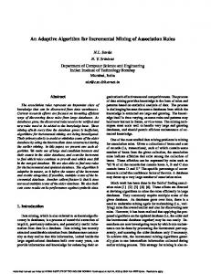
figurations for four ISCAS89 circuits. This plot shows that it is possible to combine data from different runs of the incremental algorithm and plot them to find the optimal configuration. Figure 5 shows that when the length of the longest chain in the broadcast mode is close to the length of the original chain, the reduction factor is small. As the length of the longest chain decreases and the number of chains increases, the reduction factor increases and reaches a maximum. After the maximum, the reduction factor decreases as the chain length becomes smaller. The main use of this plot is to find this maximum reduction point.
The experimental results for test application time for circuits s13207, s15850, s38417 and s38584 is shown in Table 5. The columns in Table 5 present the ILS configuration, the number of serial patterns, the tester cycles that is required to apply the serial patterns, the number of broadcast patterns needed, the tester cycles that is required to apply the broadcast patterns, the total tester cycles required, and the test application time reduction factor. The results for each circuit is separated by two horizontal lines. The best configurations are highlighted in bold.
4.1 Conclusions Illinois Scan Architecture (ILS) methodolgy is an effective way of reducing test costs by lowering the test data bits as well as the number of cycles needed to test a chip. In this paper, we presented a new incremental algorithm for test generation in ILS designs. The incremental algorithm is able to generate tests for several ILS configurations in a
The data for all the incremental algorithm runs for a circuit were combined and plotted in Figure 5. The plot shows the data and time reduction factor versus different ILS con6
Table 5. Test Application Time Reduction Using Incremental Algorithm
Config fs13207 ILS-400 ILS-200 ILS-100 ILS-50 ILS-25 fs15850 ILS-300 ILS-150 ILS-75 ILS-25 fs38417 ILS-840 ILS-420 ILS-210 ILS-105 ILS-21 fs38584 ILS-1024 ILS-512 ILS-256 ILS-128 ILS-64 ILS-32
Serial Scan Num Patterns Cycles 475 318919 1 1339 8 6029 31 21439 55 37519 247 166159 439 263119 1 1195 12 7773 27 16743 114 68769 943 1545327 11 19643 18 31102 23 39287 34 57294 589 965829 619 900859 1 2905 7 11623 11 17435 46 68290 113 165641 280 408292
Broadcast Scan Num Patterns Cycles 0 669 450 180850 455 91655 429 43429 380 19430 178 4653 0 597 440 132740 404 61154 403 30703 299 7799 0 1636 925 778765 907 382267 816 172386 759 80559 282 6225 0 0 632 648824 609 312929 614 158054 587 75851 523 34059 425 14057
Total Cycles 319588 182189 97684 64868 56949 170812 263716 133935 68927 47446 76568 1546963 798408 413369 211673 137853 972054 900859 651729 324552 175489 144141 199700 422349
Reduction Factor 1.00 1.75 3.27 4.93 5.61 1.87 1.00 1.97 3.83 5.56 3.44 1.00 1.94 3.74 7.31 11.22 1.59 1.00 1.38 2.78 5.13 6.25 4.51 2.13
in Proc. of the IEEE VLSI Test Symp., April 1992, pp. 55-60.
single run and was shown to be many times faster than the original non-incremental algorithm. The incremental algorithm is used to find the best ILS configuration among several different configurations.
[5] E. M. Rudnick and J. H. Patel, “A genetic approach to test application time reduction for full scan and partial scan circuits,” in Proc. of the Int. Conf. on VLSI Design, January 1995, pp. 288-293.
References
[6] S. Lee and K. G. Shin, “Design for test using partial parallel scan,” IEEE Trans. on Computer-Aided Design, vol. 9, pp. 203-211, February 1990.
[1] L. R. Harriott, “A new role for e-beam: Electron projection,” IEEE Spectrum, vol. 36, no. 7, pp. 41-45, July 1999.
[7] S. Narayanan, R. Gupta, and M. Breuer, “Optimal configuring of multiple scan chains,” IEEE Trans. on Computer-Aided Design, vol. 42, no. 9, pp. 11211131, September 1993.
[2] V. Agrawal and M. Bushnell. Essentials of Electronic Testing for Digital, Memory and Mixed-Signal VLSI Circuits. Norwell: Kluwer Academic Publishers, 2000.
[8] S. Narayanan and M. A. Breuer, “Reconfiguration techniques for a single scan chain,” IEEE Trans. Computer-Aided Design, vol. 14, no. 6, pp. 750-765, June 1995.
[3] S. Y. Lee and K. K. Saluja, “An algorithm to reduce test application time in full scan designs,” in Proc. of the Int. Conf. on Computer-Aided Design, November 1992, pp. 17-20.
[9] D. Das and N. A. Touba, “Reducing test data volume using external/LBIST hybrid test patterns,” in Proc. Int. Test Conf., October 2000, pp. 115-122.
[4] D. K. Pradhan and J. Saxena, “A design for testability scheme to reduce test application time in full scan,” 7
Circuit s13207
Circuit s15850
6
6 Time Data
Time Data
5
Reduction Factor
Reduction Factor
5 4 3 2
4 3 2
1 400
300
1 600
200 100 ILS configuration
500
400 300 200 ILS configuration
Circuit s38417
Circuit s38584
12
7 Time Data
Time Data
6
Reduction Factor
10
Reduction Factor
100
8 6 4
5 4 3 2
2 1000
800
600 400 ILS configuration
1
200
1000
800
600 400 ILS configuration
200
Figure 5. Time and Data Reduction Factor vs. ILS configuration [10] A. Jas, C. V. Krishna, and N. A. Touba, “Hybrid BIST based on weighted pseudo-random testing: A new resource partitioning scheme,” in Proc. of the IEEE VLSI Test Symp., April 2001, pp. 2-8.
[16] P. H. Bardell and W. H. McAnney, “Self-testing of multichip logic modules,” in Proc. of the Int. Test Conf, Nov. 1982, pp. 200-204. [17] F. Hsu, K. Butler, J. H. Patel, “A case study on the implementation of the Illinois scan architecture,” in Proc. Int. Test Conf., October 2001.
[11] A. Jas, B. Pouya, and N. A. Touba, “Virtual scan chains: A means for reducing scan length in cores,” in Proc. of the IEEE VLSI Test Symp., April 2000, pp. 73-78.
[18] F. Brglez, D. Bryan, and K. Kozminski, “Combinational profiles of sequential benchmark circuits,” in Proc. Int. Symp. on Circuits and Systems, May 1989, pp. 1929-1934.
[12] Y. Zorian, “Test requirements for embedded corebased systems and IEEE P1500,” in Proc. Int. Test Conf., October 1997, pp. 191-199.
[19] I. Hamzaoglu and J. H. Patel, “New techniques for deterministic test pattern generation,” in Proc. IEEE VLSI Test Symp., April 1998, pp. 446-452.
[13] A. Chandra and K. Chakrabarty, “Frequency-directed run length (FDR) codes with application to systemon-a-chip test data compression,” in Proc. of the IEEE VLSI Test Symp., April 2001, pp. 42-47.
[20] I. Hamzaoglu and J. H. Patel, “New techniques for deterministic test pattern generation,” Journal of Electronic Testing: Theory and Applications, vol. 15, pp. 63-73, October 1999.
[14] I. Hamzaoglu and J. H. Patel, “Reducing test application time for full scan embedded cores,” in Dig. Papers, 29th Int. Symp. Fault-Tolerant Comp., June 1999, pp. 260-267. [15] K-J. Lee, J-J. Chen, and C-H. Huang, “Using a single input to support multiple scan chains,” in Dig. Tech. Papers, 1998 IEEE/ACM Int. Conf. Computer-Aided Design, Nov. 1998, pp. 74-78. 8