4, 2001. AN OBJECT-ORIENTED MODELLING. APPROACH FOR DYNAMIC COMPUTER. NETWORK SIMULATION. D. Anagnostopoulosâ and M. Nikolaidouâ.
International Journal of Modelling and Simulation, Vol. 21, No. 4, 2001
AN OBJECT-ORIENTED MODELLING APPROACH FOR DYNAMIC COMPUTER NETWORK SIMULATION D. Anagnostopoulos∗ and M. Nikolaidou∗
Abstract
network entities. Object-oriented modelling contributes to this. Differences between simulation tools include the level of detail in the description of network components, modelling decisions and techniques, and the degree of automation offered. Communication-oriented simulators are the most widely accepted simulation software category [3], as they reduce program development time. Simulators enable automated model construction through the use of built-in modules, which are closely related to the components of a communication network [1, 2]. When one is drawing conclusions about network performance, simulation tools are based on the average, or the worst-case, scenario and thus they contribute only to an “off-line" performance analysis of an existing network. This is because they use hypothetical data to represent real conditions. Intensively dynamic network behaviour, however, considerably reduces the expressiveness of such data. When trace-driven simulation is used, the expressiveness of data is also restricted to the specific real conditions under which they were extracted. The modelling approach we introduce involves the development of a simulation environment that uses real network data to reach conclusions for network performance in the near future. It is based on the real-time simulation methodology we have previously proposed, consisting of the following main phases: modelling, experimentation, and remodelling [4]. The real-time objective imposes new requirements for the network modelling process [5]. Adopting specific modelling techniques is thus necessary to reduce simulation time, to dynamically modify the model, and to ensure its validity. The execution time of the model is critical, as it relates to the collection and processing of real-time data from the network. In this work, we do not discuss the issue of making the network model run faster than the real network; however, generic approaches in this direction have been proposed [6]. Remodelling (i.e., performing dynamic modifications to the model) during the experiment is also a prerequisite in order to customize the model to real conditions without recompilation. Finally, the validity of network component models must be preensured. The network operation scenarios handled through this approach include the most common cases, such as the
Recent work indicates simulation of dynamic network behaviour may be used as an effective tool for predicting network performance, for the near future. Conclusions from such simulation, when applied to network performance, can greatly enhance network management. To accomplish this, such simulation must be performed in real time, with the consequent effect of drastically reducing both modelling and experimentation requirements. This article introduces a modelling framework for the uniform manipulation of network entities with minimum time overhead. This framework, which is based on modular and hierarchical modelling, extends to both primitive and composite entities such as communication protocols and nodes, and ensures that composite network entity models are preconstructed.
The
framework thus enables the model to reliably depict variable network structure and operation parameters.
Sample measurements are
presented to illustrate the type of dynamic network behaviour that such simulation techniques have to deal with. The measurements also illustrate the adaptability of the model, including reduced time overhead for simulation experiments.
Key Words Network simulation, network modelling, object-oriented modelling, real-time simulation
1. Introduction Network performance evaluation is used extensively to extract reliable conclusions for network performance under real conditions. Simulation modelling, on the other hand, enables the representation of real conditions, the combination of complex entities, and the analysis of the overall network architecture. Numerous simulation tools, classified according to their orientation and modelling framework, are actively used in the networking discipline [1, 2]. When simulation extends to the overall network architecture and is not restricted to specific entities, modelling tools adopt a layering scheme and use common modelling principles for the ∗
Department of Informatics, University of Athens, Panepistimiopolis, Athens 15771 Greece; e-mail: {dimosthe, mara}@di.uoa.gr (paper no. 1998-121)
1
initiation of new applications (when these have a significant impact on the overall network load), node start up, active node crash, critical modification of application load, and application termination. Due to performance issues (because simulation is executed in real time) we emphasize the quantitative issues of communication and not the in-depth analysis of protocol mechanisms. The modelling framework provides extended abilities to conduct network simulation experiments, without imposing limits on the efficient representation of network entities. Current orientation is towards local area networks. In the following sections, we present the modelling decisions and techniques proposed for individual entities. Sample measurements indicating dynamic network behaviour under real conditions, along with conclusions, as perceived from a prototype simulation environment, are briefly discussed in the last section.
In this layering scheme, data transmission follows the following well-known sequence: applications feed processing nodes with data, which in turn are processed by the highest-layer protocol and then forwarded to the next lower layer. This continues until the protocol data unit (PDU) reaches the media access control (MAC) layer. The data are finally transmitted through the physical communication link. Reception of data follows exactly the reverse order, until data are delivered to the destination applications. Communicating nodes, on the other hand, are responsible only for transferring data units between interconnected networks. When data are received from a communicating node, they are forwarded to the layer where relaying is performed and then transferred to the peer protocol layer of the destination node. The following issues must be considered in this process: first, the highest supported layer is not predetermined. This does not apply to the lowest layer, as media access mechanisms must be provided. Second, it is possible that intermediate layers are not supported. The layering scheme used should deal with these issues. Network models consist of composite and primitive models. Applications and communication links are perceived as primitive entities. Network nodes are decomposed in terms of their communication and processing elements (virtual entities, which are used to represent the communication and processing properties of the node) [10]. Because our orientation is towards communication issues, the processing element can be modelled as a primitive entity. The communication element (i.e., the protocol stack) is composite, formed on the basis of the protocols operating in each node. Network nodes can be either processing or communication nodes. When referring to the lower layers, protocol stacks of processing nodes can be considered to be identical. A simple local network N thus consists of n1 , n2 , . . . , nk processing nodes. The communication element is formed as a sequence of protocols pr1 , pr2 , . . . , prn , starting from the MAC layer. As nodes are identical as far as communication-oriented issues are concerned, network N = {ni , 1 = i = k} and ni = (pr1 , pr2 , . . . , prn ). A widely used TCP/IP-Ethernet protocol stack could thus be represented as (10BaseT, _ ,IP,TCP). The logical link control (LLC, IEEE 802.2) layer is not supported here. In this way, it is possible to represent stacks with acceptable protocol combinations up to the highest supported layer. An advantage of this scheme is its ability to support only specific layers and not to predetermine the highest layer. However, each layer is modelled through a single protocol. When two or more protocols operate in the same layer, a single model must be constructed to provide the aggregate functionality. Extending protocol stack modelling to the layer where reliability is ensured (i.e., the transport layer) is strongly enabled, as application modelling is then close to clientserver programming over sockets and emphasis is given to purely communication issues. In this way, we can view applications as sockets operating above the transport layer. Each node ni is then linked to a set of applications Ai = {ai1 , ai2 , . . . , aixi }, where xi is the number of applications
2. Network Modelling Framework Because networks are variable structure systems, dealing with structure modifications during the simulation experiment requires the use of modular models [7]. Modular models often have a hierarchical structure according to which components are coupled together to form larger models. The coupling concept, combined with object orientation, enables late binding, an essential feature for accomplishing remodelling without recompilation [8]. Remodelling requirements are thus handled through object-oriented modelling and the use of preconstructed model components, which are organized in object hierarchies. Object hierarchies reside in model libraries. Either primitive (atomic) or composite models can be preconstructed, representing the key network entities. As preconstructed models must correspond to the entities that are likely to participate in a network, all acceptable entity combinations must be offered. Preconstruction of primitive and composite models is thus performed for all higher level entities corresponding to the accepted combinations, and extends to the level where structural modifications may be encountered. Network component preconstruction also enables automated model generation. Whenever additional primitive models are constructed and inserted in object hierarchies, the corresponding composite models can be simultaneously derived and made available. The following are considered to be key network entities of local networks, modelled in the form of preconstructed components [9, 10]: communication protocols, communication and processing nodes, and network applications. The above classification corresponds to a discrete layering scheme of network operations [11], such as the OSI reference model. Hierarchical layering enables the construction of more complex models by extending the behaviour of existing objects, and ensures the uniform manipulation of all equivalent network entities through a common public interface. As hierarchical layering extends to the composite network entities, implementation of this scheme proves to be rather complex. However, the outcome is the preconstruction of all necessary network components, and this in turn ensures their availability. 2
of ni . The structure of a network model is depicted as a composition tree in Fig. 1, corresponding to the structural decomposition of the network, using two types of links, composition and in_out. This is the base structure of the network. It is determined during the initial specification phase and is maintained in all network operation scenarios under consideration. In_out links represent the coupling relation between node and application models.
derived models should be constructed for the corresponding applications of a single layer. The nine primitive objects can be reused. However, 20 application models must be derived to provide the equivalent functionality for each additional layer. A sample code fragment for the above hierarchy implementation (in Modsim III) is depicted in Fig. 3. DLUniNorApplObj is the application model that forwards data to the data link layer, and it is constructed as an ancestor of the generic data link model DataLinkApplObj. Data creation and size estimation follow uniform distribution and normal distribution, respectively. Methods ScheduleDataUnit() and EstimateSize() are inherited from the primitive objects UniformTimeObj and NormalSizeObj to provide the required functionality.
Figure 1. Abstract network composition tree. In the following section, we discuss the realization of the modelling framework we have introduced. We do this for the main network entities: namely, applications, communication protocols, and network nodes. Communication links are modelled at a level of abstraction through representation of their main features, such as capacity and error rate. This is because the characteristics of transmission are determined by the media access protocol.
2.2 Protocol Modelling Communication protocol modelling is performed here according to hierarchical layering. Because protocols perform operations corresponding to well-defined layers (not necessarily a single one), modelling issues depend on the specific layer under study. Protocols are viewed as primitive entities, as protocol mechanism complexity is inherent. Models of the same layer, as equivalent entities, become members of the same object hierarchy, and inter-protocol communication complexity is handled during the composition of node models. Even though protocols are considered to be primitive objects, it would also be possible to decompose them in terms of the elements that implement specific mechanisms, such as the media access mechanism. However, such a systematic analysis has the disadvantage that not all mechanisms are supported by protocols of the same layer, as with flow control in the transport layer. Another disadvantage is the fact that they are not standardized. Consequently, a protocol decomposition scheme for the various layers would require numerous simplifications and would also be of questionable effectiveness.
Figure 2. Sample application model hierarchy. 2.1 Application Modelling Applications are associated with a single node but operate independently, generating and forwarding data to the node as well as receiving data originating from other applications. To achieve the uniform manipulation of protocol models, nodes are responsible for forwarding data units to the highest supported layer. As it is impossible to determine this layer, application models must be in a position to generate data units for all eligible layers. This is also required for studies that are oriented towards single layers. Because different layers handle different data units, a distinct application model must be provided for each layer. At the very least, this model must support mechanisms already established in commercial tools [1] for determining the scheduling, type, size, and destination of data units. The proposed modelling scheme for applications, emphasizing the data link layer, is presented in Fig. 2. We have built the object class hierarchy using a generalization relation between classes [12], so that object structure is inherited from top to bottom, and also through multiple inheritance. This process comprises the following steps: 1. Construction of the base application mode 2. Construction of a generic model for each layer supported, as an ancestor of the base application model 3. Construction of the primitive objects that provide the required functionality for data unit scheduling, data unit size, and so on 4. Derivation of application models, as ancestors of the corresponding layer generic model and the primitive objects that provide the specific functionality We have used multiple inheritance to implement the structures required for representing specific features of applications. If, for example, there are five possible ways of scheduling the creation of data units and four of determining their size (e.g., according to corresponding distributions), nine primitive objects should be provided and 20
Figure 3. Sample code for constructing the application model hierarchy. To ensure the uniform manipulation of protocol models, we suggest the provision of abstract modelling schemes for all discrete layers. We could thus depict a protocol hierarchy for the MAC layer as in Fig. 4. This hierarchy would be depicted as part of the overall protocol hierarchy. Figure 4. Sample protocol model hierarchy. 2.3 Node Modelling The modelling scheme introduced is concerned with communication-oriented issues and ensures the uniform manipulation of node models. Preconstruction of the composite models is performed for all the accepted protocol combinations. The modelling scheme is presented in Fig. 5. The object class hierarchy has been built using multiple inher3
• Extendibility when constructing node models that support additional, higher layers In addition, a computer group model can also be used to reduce the model execution time. We can, nevertheless, only adopt this concept when a number of nodes have more or less the same behavioural characteristics. This, however, is uncommon under real conditions.
itance and a generalization relation between classes. This process comprises the following steps: 1. Construction of the base node model 2. Construction of a node model for the first supported layer as an immediate ancestor of the base model, with a specific protocol as an additional attribute; this step is executed for all protocols of the layer 3. Construction of node models for the upper layer as ancestors of the appropriate first-layer node models, with the corresponding protocols as additional attributes 4. Execution of step 3 for all higher layers, up to the highest supported layer The base model provides the primitive node functionality along with the mechanisms for inter-protocol communication. When supporting only the first layer, there should be as many node models as MAC layer protocols. Repeating this process for all layers results in an object hierarchy where each node is a unique, complete model with a specific protocol stack. When a stack needs to be extended to support a higher layer, an ancestor, which has the specific protocol as an additional attribute, is directly constructed. In this way, the accepted protocol combinations are efficiently modelled and no identical models are built.
2.4 Model Generation and Manipulation The framework for composite entity modelling provides a concise means of building model hierarchies. This process can be more efficient when supported by a simulation model generator that constructs higher level models according to the acceptable component combinations, and it can thus contribute to the availability of component models. Figure 6. Automated model generation example of application modelling. A model generation example of application modelling is presented in Fig. 6. The object hierarchy corresponds to the code fragment in Fig. 3. As additional methods are provided for scheduling data unit creation and estimating unit size, these are modelled through the primitive objects ExponentTime and ExponentSize. We have therefore constructed the three corresponding application models, as shown by the dotted lines. The code fragment generated is presented in Fig. 7. Obviously, as in a real case there are more features than data unit scheduling and size to be modelled, the complexity encountered cannot be handled efficiently by manual means.
Figure 5. Sample node model hierarchy. As previously discussed, when modelling a protocol stack, an intermediate layer, such as the LLC, can be supported or not. In the first case, an LLC node model can be constructed as an ancestor of a first-layer model. In the latter case, where the LLC layer is not supported, the preconstructed NULL protocol model can be used. NULL protocol only forwards data units to the protocol of the higher or the lower layer, depending on whether reception or transmission is performed, without any additional time lapse. In this way, it is possible to model protocol stacks when specific layers are not supported. To give an example, if three protocols were provided for the MAC layer, one for the LLC layer, and two for the network layer, there would be a maximum of 12 possible protocol combinations that need to be constructed. This would be the case if all combinations are accepted (in terms of protocol compatibility). This number increases when certain layers are not supported and the NULL protocol is used. Finally, to handle cases where more than one protocol is active in the same layer (e.g., TCP and UDP in the transport layer), a protocol wrapper is constructed for this specific layer and is responsible for forwarding data units to the appropriate protocol. This ensures that inter-protocol communication between layers is performed uniformly, even in the latter case. The advantages offered by the node modelling scheme are summarized as follows: • Uniform manipulation of protocol models • Ability to either support specific layers or not • Ability to model protocols corresponding to more than one layer, or more than one protocol corresponding to a single layer
Figure 7. Code generation when constructing new primitive objects. Because all the above operations are performed on structures residing in object libraries, it is important to address the issue of manipulating these structures. When retrieval is performed, the model required is directly imported, as the overall structure is precompiled. Apart from retrieval, which is the only action that occurs during experimentation, three other actions are likely to be performed: insert, update, and delete. Insertion of new nodes in a model hierarchy is performed through creation of an ancestor of either single or multiple objects, thus extending the behaviour of the existing object nodes. When referring to high-level structures, this process can be automated through model generation techniques, as shown in Figs. 6 and 7. The overall hierarchy is then subjected to recompilation. Model update is performed with minimum overhead when modifying the implementation part of a method, whereas object definition modifications must be propagated to other objects. Model hierarchies are then subjected to recompilation. However, model updates are not likely to be performed for composite models, as these are built on the basis of existing, primitive models. The “Delete" operation is not common, either, because it is used only to remove objects that provide a functionality 4
A2 , appl12 ∈ / A1 , appl42 ∈ / A4 and concludes that the network structure was modified during the preceding interval. Remodelling activity is thus invoked to restore the consistency between the model and the network, and simulation results are discarded. Remodelling removes and disposes of the corresponding components from the model composition tree and reconfigures the coupling between the remaining components. When all modifications are accomplished, the model is once more subjected to experimentation, starting from the current real-time point.
that is no longer needed. When deleting, recompilation is also required. However, before deletion it must be ascertained that there are no pending references to these object classes. The above issues regarding the manipulation of object structures apply to all entity models described in the previous sections. 3. Network Experimentation Network performance evaluation under real conditions requires handling of the scenarios causing modifications to the network state, as the model must be adapted to the new conditions, while maintaining reliability of results. It is therefore essential that the simulation environment be capable of collecting and processing real network data, as well as drawing conclusions in real time. Numerous networking issues emerge during the network operation. We can divide these issues into two main categories: those that intervene in the network structure and those that intervene in operation parameters. Structural modifications acquire an increased degree of complexity. We discuss the following common networking issues: activation of a network node, active node crash, critical modification of an application network load, change in data unit (packet) size, and so on. To indicate the occurrence of any of the above scenarios, specific parameters of the model and the network are monitored. We refer to these parameters, which are commonly defined for both systems, as monitoring variables, and analyze and compare the corresponding states of the model and the network, which are expressed through appropriate monitoring variables [13]. Due to the stochastic nature of simulation, comparisons can indicate both modifications to the state of the network and deviations between the model evolution and the actual trace. Comparisons are performed through a well-determined set of statistical measures, indicative of the network performance, such as end-to-end delay and aggregate throughput, when the auditing interval (i.e., the time period where both systems are being monitored) has elapsed. Auditing activity (i.e., examination of both systems’ evolution) is regularly initiated after the preceding interval and exploits monitoring variables from both systems to determine whether the model is close to the actual network trace. This is the feature that enables the reliability of simulation predictions. We perform network modelling according to the composition tree in Fig. 1. A sample local network used to describe the experimentation framework, consisting of four processing nodes, is given in Fig. 8. The most significant applications generating input data (in terms of network load) and the interconnection scheme between applications are also included.
A node activation event imposes the integration of additional components within the network model, and thus the appropriate model is directly imported, initialized, and dynamically linked to the existing model. If, for example, node5 with protocol stack (10BaseT, _ ,IP,TCP) was activated, the corresponding model would be initialized according to the current operation parameters, to represent the current network state. Cases such as protocol parameter, application data size, and scheduling modifications, where intervention in the model structure does not take place, are handled through adjustment of the corresponding parameters. As modifications are indicated through monitoring variables, appropriate variables should be defined for all networking issues under consideration. If, for example, data transmission parameters of appl1 2 were modified, resulting in a different data unit size, the corresponding parameter would be set to a new value, taking into consideration both previous and current measurements. Such tasks are accomplished with less complexity and time overhead than structural modifications. There are also issues, such as the transmission speed, that are closely related to specific protocols. In this case, potential changes can be handled using a different protocol stack, as a structural modification. However, many networking issues, such as transmission speed, flow control parameters, and routing strategies, are not commonly modified during a network operation. To summarize, networking issues are classified according to whether they cause structural modifications or not. In the first case, model components are inserted, deleted, and coupled with the existing model so that the variable network structure is efficiently represented. In the second case, the appropriate parameters of both the aggregate and individual models are adapted to the current network state and operation. Monitoring variables must be defined and examined prior to reaching conclusions on such issues. The way variables are examined and conclusions are drawn is determined by the auditing algorithm. It should also be noted that the capabilities provided for traffic modelling are undoubtedly reduced in comparison with those of traditional simulation, as traffic analysis cannot be very effective in real time. We thus suggest use of renewal traffic models as an efficient approximation, as used in the prototype implementation we discuss below. Further discussion on experimentation and remodelling activities can be found in [13].
Figure 8. Network structure modification example. If node2 crashes, monitoring data are collected and cross-examined to indicate potential modifications or deviations between the two systems. When auditing begins, it detects that node2 ∈ / N and appl21 ∈ / A2 , appl22 ∈ / 5
4. Prototype Implementation
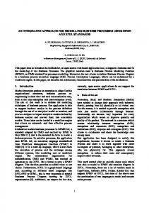
Figure 9. Variation of active sessions.
The proposed modelling guidelines are platform independent and can be widely adopted in network simulation studies. A prototype implementation was carried out for a local network of a university campus building using Modsim III simulation language [13]. The selection of this application domain enabled dealing with both structure and operation parameter modifications. The actual network under study was a 10Base-TCP/IP network, which was relatively slow, and included more than 30 computer nodes.
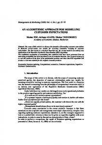
The average time required for examining whether both systems are evolving in the same direction and the execution of the appropriate actions (auditing and remodelling) is relatively low (close to 2 seconds), as indicated in Figs. 9 and 10, and the duration of the auditing interval is 60 seconds. As the two-second period is dead time, this contributes to the effectiveness of the simulation experiment.
Network components were modelled according to the proposed framework so that the key features of communication protocols were represented. Model manipulation and modification were performed in real time during the simulation experiment.
5. Conclusion
Figure 10. Variation of throughput.
The modelling approach that we have introduced has contributed to the manipulation of network models with minimum time overhead during execution of simulation experiments. Because of this, consistency is maintained between the model and the network, and predictions can be successfully made regarding network performance for the near future. Maintaining consistency is the feature that ensures the reliability of simulation predictions, even though dynamic network behaviour may sometimes make it unfeasible to take advantage of predictions. We have discussed in depth a uniform, concrete modelling framework for the main network entities. This framework can be widely used in network simulation. Although these concepts are currently applied in computer networks, application in other domains, such as routing algorithms, could also be considered. Our research is geared towards integration of the results extracted within the network management environment in order to improve its effectiveness by taking advantage of simulation predictions for the near future.
The simulation environment was used in conjunction with SUNnet Manager NMS in order to extend management capabilities over the Ethernet segments, and contributed to obtaining results for network performance in the near future and the indication of potential problems, such as excessive input load. An example of the experimentation process is presented in Figs. 9 and 10. The throughput and the number of active sessions in the model and the actual network are plotted for 17 consecutive time intervals (1,052 seconds). Simulation predictions are obtained at time points prior to those corresponding to real time. When values of these measures in the model deviate from the real observations, the model is appropriately modified. These time points are depicted with marks below the horizontal axon (note that the marks are not positioned identically in the two figures, depicting the corresponding deviations). When remodelling occurs, the model behaviour is closer to the actual network trace within the next auditing interval. However, if the network structure and operation parameters are repeatedly modified, the model is often subjected to remodelling. Both the dynamic nature of the network, expressed in terms of the varying throughput and the number of sessions, and the ability to constantly adapt the model are thus demonstrated.
References [1] CACI Products, COMNET III reference manual (San Diego: CACI Products, 1997). [2] Mil3 Inc., Opnet Modeller modelling manual (Washington, DC: Mil3 Inc., 1997). [3] A. Law & M. McComas, Simulation software for communication networks: The state of the art, IEEE Communications Magazine, 1994. [4] D. Anagnostopoulos et al., A conceptual methodology for conducting faster-than-real-time experiments, SCS Trans. on Computer Simulation, 16(2), 1999. [5] D. Anagnostopoulos & M. Nikolaidou, Applying real time simulation in the LAN domain: Modelling considerations, Simulation Modelling and Analysis (SAMS), 18(7), 1995. [6] K. Lee & P.A. Fishwick, OOPM: An object-oriented multimodelling and simulation application framework, Simulation, 70(6), 1998. [7] T. Pawletta, B. Lampe, S. Pawletta, & W. Drewelow, An object-oriented framework for modelling and simulation of variable structure systems, Proc. SCS SCSC ’96, Portland, OR, USA, 1996. [8] B.P. Zeigler, Object-oriented simulation with hierarchical, modular models (copyright held by author, 1995: originally published by Academic Press, 1990). [9] J. Cramer & J. Magee, Configuring distributed systems, Proc. 5th ACM Workshop on Models and Systems for Distributed Systems Structuring, Mont St. Michel, 1992. [10] M. Nikolaidou, D. Anagnostopoulos, & P. Georgiadis, Modelling and simulation of distributed systems, Proc. IASTED Modelling and Simulation Conf. ’96, Pittsburgh, PA, USA, 1996.
Due to the increased number of deviations encountered in this example, results are often discarded during remodelling and simulation time is re-initiated from the current time point. Simulation predictions thus refer only to nearfuture time points. In the above example, whenever auditing is performed, simulation time is at least one interval ahead of world time, even when remodelling has previously occurred, regardless of the number of active nodes and the network load. Taking advantage of simulation results to reach reliable conclusions is possible only when both systems are moving close enough for a considerable amount of time [4], as for example at time point 1,052 in Fig. 9. The decision concerning the reliability of predictions is taken based on the comparison between the real observations and the corresponding simulation results obtained at previous realtime points. 6
[11] S. Jones & C. Smythe, A generic framework for the simulation analysis of protocol layered communication systems, Proc. MASCOTS’93, Simulation Series, 25(1), 1993. [12] P. Fishwick, OOPM/RT: A multimodeling methodology for real-time simulation, ACM Trans. Modelling and Computer Simulation, 9(2), 1999. [13] D. Anagnostopoulos, M. Nikolaidou, & G. Philokyprou, Computer network performance prediction for the near future through faster than real time simulation, Proc. SCS SPECTS’99 (part of SCSC ’99), Chicago, IL, USA, 1999.
Biographies Dimosthenis Anagnostopoulos is Assistant Professor at Harokopion University of Athens. He received a Degree and a Doctorate Degree, both in computer science, from the University of Athens in 1991 and 1996, respectively. His research interests include modelling and simulation, objectoriented systems, and distributed systems and networks, as well as modelling and performance evaluation of transportation systems. Mara Nikolaidou received a Degree and a Doctorate Degree, both in computer science, from the University of Athens in 1990 and 1996, respectively. She is currently in change of the Library Automation Centre of the University of Athens. Her research interests include distributed systems, digital libraries, modelling and simulation, and workflow systems.
7