Center for Research in Wireless Mobility and Networking(CReWMaN) ... tions, Ubiquitous Framework, Tracking Protocol. 1. .... We call this server the. Gateway ...
An Ubiquitous Architectural Framework and Protocol for Object Tracking using RFID Tags Pradip De, Kalyan Basu and Sajal K. Das Center for Research in Wireless Mobility and Networking(CReWMaN) Department of Computer Science and Engineering University of Texas at Arlington, TX 76019-0015 {pradipde, basu, das}@cse.uta.edu Abstract
detailed knowledge of what is going on in other parts of the chain. Likewise, there is not a great deal of control once the transaction has been placed. Thus even if there is visibility of some part of the supply chain pipeline, required changes cannot be effected within a short time because of lack of control. Thus we see that a real time tracking of transacted objects is a key factor to the alleviation of the above problems. In a different scenario, a similar and potentially serious problem exists in the airport where enhanced security measures are mandatory. Security could be given a major boost if passengers and baggages could be automatically tracked throughout their entire stay in the airport and their movements monitored to detect any anomaly. Moreover, it would be extremely time efficient in check-ins and check-outs if passengers and baggages could be linked to each other electronically. The effects of efficient tracking of objects not only helps during the transactions, as mentioned earlier, but also afterwards. An entirely different problem which often manifests itself and has not been given due consideration is the situation of a Product Recall. Substantial losses are incurred because no efficient technique is known by which an organization can recall all its distributed defective objects fast enough to avoid any associated damage. The problem lies in locating all the points where distribution has taken place and also to send the recall message to those points within time. Automatic object tracking records can greatly assist in efficiently searching the distributed defective objects. In the face of the above mentioned scenarios and problems, radio frequency identification (RFID) technology[12], [3] has emerged as a practical solution to aid automatic object identification and tracking. These wireless systems enable non-contact reading from a distance and their deployment is highly effective in manufacturing and other hostile environments where the employment of bar code labels was infeasible. Being a non line-of-sight technology, RFID triumphs over the bar code labels for tracking mobile objects because they can be read regardless of their orientation. RFID has
A completely visible Pervasive Transaction Environment where it is possible to link all related transactions of physical objects and trace their mobility through their entire life process, has been elusive. With the emergence of Radio Frequency Identification (RFID) based tags, it is now practicable to automatically collect information pertaining to any object’s place, time, transaction, etc. Based on the pervasive deployment of RFID tags, we propose in this paper a novel ubiquitous architecture followed by a protocol for tracking mobile objects in real-time. Our delay analysis and simulation results indicate that the delay incurred in the database update of current tag location is very low and is in the order of seconds, thus providing a very fine granularity in time for consistent location update requests. Keywords Radio Frequency Identification, Distributed Transactions, Ubiquitous Framework, Tracking Protocol.
1. INTRODUCTION The management of distributed transactions[1] of physical objects among different organizations, and their realtime mobility tracking [2] [4], [5], [10] which also requires linking separate independent but related transactions, is a major challenge. Given the multitude of products being developed in diverse areas and the simultaneous globalization of today’s market, the complexity in the international supply demand relationship is also escalating. This has resulted in the transaction processes being exposed to higher risks. Mismanagement, leading to excessive or mismatched inventory contribute to the risk of reworking stock and penalties for non-delivery of goods, thus precipitating financial losses. Moreover, there is always the human error factor which adds to the woes of supply chain management. A careful study of the way a supply chain works, pinpoints two major areas which are the clue to developing confidence in the chain - visibility and control. By visibility we mean that it is often the case that one member of the chain has no 1
Proceedings of the First Annual International Conference on Mobile and Ubiquitous Systems: Networking and Services (MobiQuitous’04) 0-7695-2208-4/04 $20.00 © 2004 IEEE
2. NETWORK ARCHITECTURE In our proposed architecture, every Physical Object is uniquely identified by an RFID tag or electronic product code (EPC) [7] attached to it. From this perspective, within this network, a physical object is nothing but an EPC tag and so the terms would be used interchangeably. The components of this architecture as depicted in figure 1 are (i) RFID Readers, (ii) Savants and (iii)PML Servers. Our architecture is hierarchical in nature, organized as a balanced
tree topology. At the leaves of this topology, multiple RFID readers are engaged in continually picking up EPC tag information attached to the mobile objects. Readers would be managed by a Reader Management Module (RMM) and for every EPC, the RMM basically captures the following information: (i)the EPC of the tag read, (ii) the EPC or ID of the reader that scanned the above tag, and (iii) the reading timestamp. Gateway PML Server (Org B)
Readers
.. .
EdgeSavant
Internet
.. . PML Server
Intermediate Savant
Gateway PML Server (Org A)
Intranet PML Server
EdgeSavant
EdgeSavant
.. .
EdgeSavant
.. .
.. . .. .
.. .
taken over the automatic identification scenario, viz, low cost transponders offering multiread capabilities, low to reasonably high (64Kbits) data storage capability, wide range of data transfer rates (depending on device and carrier frequency used) and close proximity (inductive systems) to tens of meters (radiating systems) without the need for line-of-sight interrogation. This technology can be used very efficiently to pervasively tag physical objects so that they can be tracked through the entire transactional processes. By the term transaction, we basically qualify the movement of a tagged object from its source to destination passing through different organizations and hierarchy and possibly changing ownership in the process. It has been rightfully pointed out in [11] that these RFID tags are wireless, networked, pervasive computers, successfully integrated into their environment. This nascent concept of pervasive RFID tag deployment holds a lot of promise for many application areas such as mobile commerce [6]. In this paper, we propose an architecture to be deployed for implementing transactions of physical objects tagged with RFID labels so that organizations are able to track their mobility in real-time. This architecture is a generic one and can be deployed in several similar scenarios. Being inherently distributed in nature, the architecture takes care of scalability issues and fits well with the implementation of different heterogeneous Service Level Agreements (SLA) between various organizations. We describe the details of individual components of our architecture and also the distributed protocol for mobility tracking that can be pervasively deployed by organizations. Our protocol delay analysis shows that the worst-case time required to read and update the new location of migrated objects is of the order of several seconds. Hence queries for consistent current location information can have a very fine granularity in time. The rest of the paper is organized as follows. Section II and III illustrates the network architecture and the protocol for distribution and tracking of the physical objects within transactions, respectively. Section IV deals with a delay analysis of our architecture. Section V presents results on the analysis while Section VI concludes the paper with directions for further research.
Readers
Figure 1. The Architecture Schematic Since this information has to be managed at a very fast rate, several RFID readers are homed at a data routing server residing at the next higher level of the architecture hierarchy. These servers in turn form a distributed hierarchical structure amongst themselves in order to manage the data flow. They smoothen and aggregate the data coming from the RFID readers and correct errors made while reading and perform such operations as data capturing, data monitoring, and data transmission. These distributed data routing servers are called Savants. In our architecture, the readers are connected to the Savants using standard LAN connections (wireless or wireline). In the tree-like structure that the savants themselves are organized in, the leaf nodes are called Edge Savants and the internal nodes called the Internal Savants. Details about how the Savant works are dealt with in [8]. The readers would be connected to the corresponding Edge Savant that collects real-time EPC data. Although the EPC uniquely identifies individual objects, all the useful associated information is written in a new, standard language called the Physical Markup Language (PML) [9] that is based on the widely accepted eXtensible Markup Language (XML) and designed as a common lan-
Proceedings of the First Annual International Conference on Mobile and Ubiquitous Systems: Networking and Services (MobiQuitous’04) 0-7695-2208-4/04 $20.00 © 2004 IEEE
guage for describing physical objects. A PML file will contain both static and dynamic data pertaining to an object and would be stored in a server called the PML Server which resides at a level above the savants in the hierarchy. Multiple savants are homed at a PML Server. Within an organization, several of these servers communicate over a secure intra-network. The PML Server of an organization which contains information about an object owned by that organization is referred to as the Home PML Server (H-PML) with respect to that object. The static data pertaining to an object would include: (i) EPC class-level manufacturer’s data, (ii) EPC Serial Level Manufacturer’s data, and (iii) Transaction documents, whereas the dynamic data would be generally comprised of mobility information like serial level tracking and location centric data. The static data would be stored in a database called the Information Database or IDB. The dynamic mobility information would be stored in mobility management registers. Following on similar lines as the Mobile Cellular Systems, we propose that every EPC would be associated with its Home Location Register or HLR[16] maintained at the corresponding H-PML that will keep all the pointers to its information database. As soon as an object leaves its current location, the information at the HLR is updated which keeps a history of the PML servers visited by the EPC. The HLR-EPC association is permanent, unless the EPC is removed from its home and allocated to another home. For instance, change of EPC ownership makes the new owner’s HLR the new home of the EPC. Likewise, a dynamically changing Visitor Location Register or VLR[16] cache would be located at corresponding PML Servers to keep information about a visiting object. When a new object enters the field of a particular RFID reader, the corresponding PML Server copies all relevant information for this EPC from the HLR at its H-PML into its local VLR. By relevant information it is implicitly assumed that information is exchanged depending on the organizations’ respective Service Level Agreements (SLAs). Thus, in a typical organization’s network, there would be a HLR and VLR associated with each PML Server. In addition to storing objects’ information, the PML servers are basically configured to answer queries coming from other organizations or end-users for information on any particular EPC. These queries are answered by consulting the corresponding PML file fragment containing the required information for the specific EPC. To handle queries and transactions with other organizations, one of the PML Servers would perform Gateway functions to facilitate interorganizational transaction processes. We call this server the Gateway PML Server (GW-PML). Now, in order to retrieve information about a particular EPC, its H-PML needs to be identified first. Thus, there has to be a mapping between the EPC of a particular object and
the IP address of its H-PML. An Object Naming Service (ONS) which is an extension of the Internet Domain Name Service (DNS), would be used for dynamic service location for that EPC. For any information update regarding an EPC, the ONS is queried to retrieve the IP address of the H-PML after which the update required is sent to the H-PML. We divide the RFID Network Architecture into two major segments - The Intra Organization Network and the Inter Organization Network. As shown in Figure 1, two transacting organizations have their independent RFID networks that will include the different components. These two organizations would internetwork via their respective GW-PMLs as shown. The GW-PMLs would also act as protocol converters between two different implementations so that the transaction process will extend its scope and be scalable. The protocol conversion will include both Semantic and Syntactic conversion mechanisms that are defined apriori based on the SLA of the two organizations. This conversion of the messages between the two systems based on their SLA will allow any two systems to interwork seamlessly once an SLA has been setup between them. Different sites of an organization will have a PML server (logical or physical) function . Multiple Savants of each site would be homed at the corresponding site PML server. The RFID readers of different workspace areas are connected to a Savant, based on predefined spatial and topological rules. Given the density of multiple RFID readers to provide radio coverage for an entire area some collision avoidance algorithm would be required to avoid two RFID readers trying to read the same EPC simultaneously and resulting in a collision. Collision can take place between readers attached to the same Savant or to different Savants. Reader Collision Avoidance schemes based on graph coloring algorithms have been dealt with in [15]. Collision can also take place when a single reader tries to read multiple EPCs in its read range. This collision takes place when multiple EPCs simultaneously respond to a query by a reader. A Query Tree Protocol has been proposed by the MIT Auto-Id Center [13] to deal with these collisions[14]. Thus, in a nutshell the RFID Network within an organization would include functional blocks like • PML Server • SLA-DB • HLR/VLR • a number of Savants and RFID readers interconnected in a logical tree topology.
3. THE OBJECT TRACKING PROTOCOL Central to the architecture for managing the transactions of the tagged object is their accurate tracking and visibility as they move. We need a discrete tracking mechanism
Proceedings of the First Annual International Conference on Mobile and Ubiquitous Systems: Networking and Services (MobiQuitous’04) 0-7695-2208-4/04 $20.00 © 2004 IEEE
for the physical objects because contrary to tracking in the cellular domain we are not concerned with keeping a communication session alive. Moreover, tracking these tagged objects would fundamentally be a pull based scheme as the passive tags are incapable of updating their locations. However, in the field of a reader they are always readable and thus active. Thus, a tracking protocol which is aware of the above issues, is required for the mobility management of the EPC tags. Moreover, if this protocol is designed at the application layer it would be convenient for organizations to easily and widely deploy without any modifications in the operating system of any of the participants. In this section, we try to illustrate such an application layer protocol for tracking the mobile objects. The information that is sent from the Reader Management Module to the Savant essentially includes a triplet containing the three parameters, . In a nutshell, the RFID readers sense the objects as they enter or leave their radio field and accordingly notify the corresponding Savant who in turn generates notification messages destined for the respective PML Server. It is based on these messaging that the location information at the mobility registers in the H-PML would be ultimately updated.
No Tag
Idle
New Tag Arrival/Send Synch
Recv ACK
DeSynch Sent
Synch Sent
Recv ACK No new Tag to Read/Send DeSynch
Reading
Read Tag/ Send Triplet
Figure 2. Protocol Flow Diagram for the Reader Management Module
To further elucidate our protocol, let ε denote the EPC in question. Let H-PML(ε) denote its corresponding HPML. Let Pt = {P1t · · · Plt }, St = {S1t · · · Sm t } and Rt = {R1t · · · Rnt } denote, respectively, the set of PML servers, Savants and RF Readers of organization t. The protocol consists of two levels of messaging. First, at the interorganizational level, whenever ε changes PML Servers, HPML(ε) is notified. Secondly, the intra-organizational level
No Tag Triplet
Idle
Triplet Rcvd
Synch Rcvd/Send ACK
ACK Rcvd
Synch
Desynch Rcvd/ Send ACK, Send Attach
Attach Sent
Figure 3. Protocol Flow Diagram for the Savant
is basically within the purview of a single PML server and mobility information of ε within its domain is not relayed to H-PML(ε). Whenever ε changes readers and savants, this information is stored in the corresponding domain PML server. Figures 2 and 3 show the protocol state diagrams for a reader and savant, respectively, during a tag reading process. Similarly, figures 4 and 5, respectively, show the protocol state transition diagram for the PML Server P and the H-PML, respectively. The transitions are characterized by an {Event/Action}. Figures 2 and 3 indicate that the reader Rit and the savant j St undergo a synchronization stage before Rit starts reading the tags and also relaying the information to Sjt which sends a notification attach message to the PML Server Pkt . If ε enters Pkt ’s domain for the first time it notifies H-PML(ε) by sending an attach message. The ONS is consulted to get the IP address of H-PML(ε). In practice, Pkt would try to aggregate all those EPC triplets that correspond to the same H-PML into an attach message and send it to avoid sending for every EPC. The H-PML, on receiving the attach message updates its HLR regarding the new location of the EPCs. The HLR not only updates the current location of the EPC but also keeps a history of the chain of locations along with their timestamps where the EPC was previously attached. This information is necessary for future queries by clients regarding the location of an EPC within a particular time range or more importantly, during a Product Recall. As an acknowledgement to the attach, H-PML(ε) sends an accept back to the source PML Server which can then contact the H-PML back to acquire additional information from the associated HLR to update its VLR cache. At the intra-organization level of messaging within a par-
Proceedings of the First Annual International Conference on Mobile and Ubiquitous Systems: Networking and Services (MobiQuitous’04) 0-7695-2208-4/04 $20.00 © 2004 IEEE
Detach Unrecognized
Ack/Notify destination PML Tag Unrecog Msg Recvd/Send Quarantine Details to H-PML Ack Recvd Detach Sent
Recvd Unrecog Msg from H-PML/Send Tag Unrecognized Ack, Notification to Prev PML Quarantine Notification arrived/ Discard Tag Attach Sent Recvd Accept Idle
New Tag Arrived/Send Attach
New Tag left/ Send Detach
Query Sent
Detach Ack/Notify Unrecognized destination PML
Association Unrecog/ Send Auth Fail, Query Prev PML
Update Recvd
Tag Unrecog/Send Tag Unrecog Msg
Attach Recvd
Tag OK/Send Ack, Notification Detach Recvd
Detach Recvd
Idle
Attach Recvd
Tag OK/Accept Sent Ack/Notify and Quarantine
Tag Unrecog/Send Tag Unrecog Msg
Attach Unrecognized
Figure 4. Protocol Flow Diagram for PML Server
Figure 5. Protocol Flow Diagram for the Home PML Server
ticular Pkt ’s domain, in order to detect inter-reader transition of ε, a bound can be given on the number of messages received by a savant from the reader indicating that ε has left its field before it actually notifies the associated PML Server of a possible detach. As an instance, Figure 6 depicts that the Savant receives three messages from the reader indicating that there are currently n-1 objects instead of n before it notifies the corresponding PML Server. Detachment of ε from a particular Rit is then confirmed by Sjt when it detects its attachment at a different reader. Subsequently Sjt notifies its associated Pkt of this migration. Migration of ε between readers of different savants is inferred at Pkt . If an exit was initiated by Pkt for a different PML Server, then Pkt notifies H-PML(ε) by sending a detach message. This detach message also contains the IP Address of the destination PML Server. Among the several anomalies that can result, Pkt , in response to an attach message, can receive a Tag Unrecognized message from H-PML(ε) if it is not recognized. On receiving this message from the H-PML, Pkt quarantines it and notifies the previous PML Server to which the tag was attached. All information regarding ε is then flushed from its VLR cache. When H-PML(ε) does not recognize the association of ε with a particular Pkt , or in other words, authentication fails, H-PML(ε) queries the previous PML Server of ε to get its status and sends an authentication failure message to Pkt . If unconfirmed, the H-PML will generate the corresponding exception condition. Within a particular Pkt ’s domain, the same situation takes place at a micro level when ε moves between fields of different readers. When a Pkt receives an attach message from Sjt before receiving any prior detach
message, the former would generate a leaveTag message destined to the savant to which ε was attached previously. That savant would acknowledge the leaveTag message even if it had sent an earlier detach. This confirms Pkt that the previous savant indeed does not have ε attached to it. Pkt can wait for the delayed detach message to arrive and then update its associated VLR. The messaging diagram in Figure 6 illustrates the sequence of messages for reporting the mobility information of the objects. The dotted accept signifies that the PML Server to which the Savant is attached is basically the HPML for ε. If it is not so, then the attach message is propagated to the H-PML over the Internet. The detach messages work similarly.
4. PROTOCOL DELAY ANALYSIS In this section we present a delay analysis of a location update propagation. We focus on the messaging delay incurred when n EPC tags move from one PML Server to another. We consider the delay incurred in messaging from a particular reader Rit to H-PML(ε). We have assumed the network connection from the readers to the savant and further from the savant to the corresponding PML Servers to follow standard Internet Protocols. The savant establishes a T/TCP connection with the corresponding Pkt and sends n tags read from attached readers. Pkt , likewise, works on the same lines to update corresponding H-PMLs on the tags arriving from different Savants. Our analysis is based on a few assumptions. • The reader uses the Query Tree (QT) protocol to read
Proceedings of the First Annual International Conference on Mobile and Ubiquitous Systems: Networking and Services (MobiQuitous’04) 0-7695-2208-4/04 $20.00 © 2004 IEEE
RFID Reader
Savant
Remote H-PML
PML Server
n
n
n-1
n-1
attach
accept
attach
accept
accept
n
detach
detach ack
E[Treader ] denotes the expected time to read ’n’ tags by the RFID Reader and is given by E[Treader ] = O(n) ≈ 2.88 × n
n-1
. . . .
Ttotal denotes the total average delay between reading of ε to updating it in the HLR at H-PML(ε).
detach
detach ack
detach ack
attach
accept
The above equation is expressed in terms of the average number of tags read ’n’. The linear bound for reading the tags is in conformance with the QT protocol as explained in [14]. E[TnRd−Savant ] denotes the expected time taken by the Reader to send ’n’ tags to the Savant and the Savant to process them. It is given by E[TnRd−Savant ] = Tx delay +
Figure 6. Timing Diagram for the attach / detach messages
the EPC tags [14] to avoid simultaneous tag reading collisions. • The inter-arrival time of the packets from various readers to a particular connected Sjt and also from several Savants to a corresponding Pkt follows a negative exponential distribution. • The size of the packets arriving at the Savant and PML server also follow a negative exponential distribution. The service time at a Savant or a PML Server is proportional to the size of the packets arriving and is thus exponentially distributed. • At the Savant, the arriving packets are processed to find if there are any new tag update to be sent to Pkt . An arriving packet containing all stale tags is dropped at the Savant. Similarly, processing at Pkt is done to decide whether there is a change in PML server location to notify the corresponding H-PML. Based on the above assumptions we can model the Savant and the PML Server as separate M/M/1 queuing system. The Total delay equation is basically given by Ttotal
= E[Treader ] + E[TnRd−Savant ] +E[TnSavant−P M L ] + E[TnremoteP M L ] (1)
Considering standard T/TCP protocol[18], we calculate the overall transmission delay of actually sending ’n’ tags to their respective H-PMLs. We denote this transmission delay as Tx delay. The individual parameters included in equation 1 are explained below.
(2)
E[Tsavant ] (1 − ρs )
(3)
E[Tsavant ] which is the holding time at the Savant is given by E[Tsavant ] = p × Ts1 + (1 − p) × Ts2
(4)
where p is the probability that a packet containing ’n’ tags has at least 1 new tag and is thus not dropped. ρs is defined as the average system occupancy at a Savant. Ts1 and Ts2 are, respectively, the service times at Savant for packets which contain at least 1 new tag and for packets which are dropped. Similarly, E[TnSavant−P M L ] denotes the expected time taken by the Savant to send ’n’ tags to the PML Server and the PML Server to process them. It is given by E[TnSavant−P M L ] = p × (Tx delay +
E[TP M L ] )(5) (1 − ρp )
ρp is defined as the average system occupancy at a PML Server. E[TP M L ] which is the holding time at the PML Server is given by E[TP M L ] = q × Tp1 + (1 − q) × Tp2
(6)
where q is the probability that the current PML server is the H-PML for all the tags in the packet. Tp1 denote the service time at the PML Server for packets for which either it is the H-PML or are menat for the local domain. Tp1 denote the service time at the PML Server for packets with tags to be sent to a remote H-PML. E[TnremoteP M L ] denotes the expected time taken to send the tags to the remote H-PML and update the database there. It is given by E[TnremoteP M L ] = p × (1 − q) × (AV GInternetDelay E[TrP M L ] + ) (7) (1 − ρh )
Proceedings of the First Annual International Conference on Mobile and Ubiquitous Systems: Networking and Services (MobiQuitous’04) 0-7695-2208-4/04 $20.00 © 2004 IEEE
0.4
0.2
ρh is defined as the average system occupancy at the HPML. E[TrP M L ] which is the holding time at the remote HPML is basically the service time at the remote H-PML for processing the tags and updating the database. For all practical purposes E[TrP M L ] can be assumed to be equal to Tp1
Figure
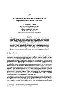
5. RESULTS The values for various parameters required to calculate the delay incurred have been tabulated in table I. An average Internet packet delay of around 40 msec has been assumed as cited in [17]. Moreover, for the T/TCP data transaction there are 2 control packets exchanged and 1 data packet for transferring the tags. Each control packet comprises of around 60 bytes. Data for sending 1 tag consumes 96 bits for the EPC, 96 bits for the reader ID and 32 bits for the timer value. Thus for a single tag 224 bits or 28 bytes are needed. Therefore, the total number of bytes exchanged for transferring n tags is 60 × 3 + 28 × n bytes. Assuming a 1 Mbps data rate we get delays ranging from 24 to 113 msec for transferring 100 to 500 tags respectively. We assume an average time to read a single tag to be around 0.47 sec as cited in [19]. With these parameters we plot the delay graphs against the probabilities p and q for different values of system occupancy ρ(which we assume to be uniform for all the systems) ranging from 0.5 to 0.8.
47.25
47.2
47.15
probability q 47.1
47.05
47 1 0.8
1
0.6
0.8 0.6
0.4 0.4
0.2
0.2
0
0
Table 1. Delay Equation Parameters Parameter Average number of tags in a packet(n) Average time to read exactly 1 tag by Reader Average system occupancy(ρ) Savant Service Time(Ts1 ,Ts2 ) PML Service Time(Tp1 ,Tp2 ) Remote PML Service Time(TRP ) Average Internet Delay(AV GInternetDelay ) T/TCP transmission delay(Tx delay) Average Link Data rate available
Value 100-500 0.47 sec 0.5 - 0.8 8, 5 msec 10, 8 msec 10 msec 40 msec 24 - 113 msec 1 Mbps
Figure 7 shows the delay for packets containing 100 tags on the average and the system having a moderate occupancy of 0.5. Figure 8 on the other hand shows a heavier traffic with packets containing 500 tags coming on the average and the system occupancy being 0.8. From the plots, it is evident that when p is high and q low, we get the maximum delay because those are the packets containing new tags which ultimately need to be sent to a remote H-PML. It is clear that, in the worst case, the time to read and update a new location of 100 tags is in the order of a few seconds and that for 500 tags with a very heavy system occupancy is of the order of a few minutes. The bulk of the time goes in reading the tags by the reader using the QT Protocol and better read time will significantly improve the performance.
Proceedings of the First Annual International Conference on Mobile and Ubiquitous System 0-7695-2208-4/04 $20.00 © 2004 IEEE
Thus the maximum delay of achieving consistency in location update information is in the order of seconds in a system with average load.
6. RELATED WORK Object or user location and tracking has been a widely studied area. Related work in this area mainly falls under the broad categories of (a) Wide area cellular networks, (b) in-building IR networks, and (c) Global Positioning System (GPS). Several location systems have been proposed for wide area cellular systems [20]. These systems have been promising in outdoor environments, but their efficacy in indoor environments is limited by the multiple reflections suffered by the RF signal. Among the indoor systems, the Active Badge System [21, 22] was an early and significant contribution. Sensors placed at known positions within a building pick up the unique identifiers and relay these to the location manager software. Another system based on IR technology is described in [23]. RADAR [24], SpotON [26] and LANDMARC [25] are among the RF based locating systems that have been developed. RADAR operates by recording and processing signal strength information at multiple base stations positioned to provide overlapping coverage in the area of interest. SpotON uses RFID technology and with the help of an aggregation algorithm performs a three dimensional location sensing based on radio signal strength analysis. LANDMARC on the other hand, uses active RFID tags for locating objects inside buildings utilizing the concept of reference tags for improving the locating accuracy. An important issue about energy conservation is addressed in [29] for devising an access protocol for an RFID based identification network. Our work is similar to some of the previous works in the harnessing of RFID technology for tracking objects. However, the difference lies in the fact that our architecture and protocol provides a high level global tracking mechanism for locating transacted objects. Our architecture could be built on top of some of the previous smaller area coverage schemes using RFID. The requirement and efficacy of such a tracking system have been pointed out earlier in [27], [28] with emphasis on inventory management although our architecture could be applied in a more generic tracking scenario. In [6], several specific key factors are identified that will enable future pervasive deployment of RFID tag and communications technology, thereby leading to the acceleration of applications for m-commerce dependent on an infrastructure that provides both seamless roaming and automatic object identification.
tags. The main crux of this architecture is the harnessing of RFID technology to provide absolute visibility and control over inter-organizational transactions and thereby enable real time tracking. Based on the network architecture, we have presented a new protocol by which the location of the physical objects would be tracked as they pass through transactions. A delay analysis of the location update of a mobile object throws light on the efficiency that this framework provides in physical object tracking. We achieve a very fine granularity in time for achieving consistency of queries for location updates. Thus, we observe that this ubiquitous deployment of RFID based object tags and automated identification and tracking enabled by our framework can circumvent the delays and errors due to human intervention otherwise incurred in distributed transactions. With the provision of absolute visibility comes in major security issues. As our future endeavor we would be looking to incorporate various security mechanisms to further bolster the architecture. Moreover, based on this architecture as the underlying framework, we are working on efficient distributed algorithms to perform product recalls.
References [1] J.A. Mills, “Large scale interoperability and distributed transaction processing”, In Proceedings of the Second International Conference on Systems Integration, 1992. ICSI 1992. [2] Kuo-Tay Chen, Szu-Lin Su, and Rong-Feng Chang, “Design and Analysis of Dynamic Mobility Tracking in Wireless Personal Communication Networks”, IEEE Transactions on Vehicular Technology, Vol. 51, No. 3, May 2002. [3] RFID Journal. http://www.rfidjournal.com/. [4] P. Bhagwat, S. Tripathi and C. Perkins, “Network Layer Mobility: an Architecture and Survey”, Technical Report, CS-TR-3570, University of Maryland (September 13, 1995). [5] A.C. Snoeren, “A session-Based Architecture for Internet Mobility”, PhD thesis, Massachusetts Institute of Technology, Dec. 2002. [6] R. Bridgelall, “Enabling mobile commerce through pervasive communications with ubiquitous RF tags”, In Wireless Communications and Networking, 20412046, 16-20, 2003.
7. CONCLUSIONS
[7] D. L. Brock, “The Electronic Product Code (EPC)- A Naming Scheme For Physical Objects”, White Paper. MIT Auto-Id Center, January, 2001.
In this paper, we have proposed a distributed Framework for ubiquitous Physical Object Tracking based on RFID
[8] The Savant - Version 0.1 (Alpha), Technical Manual. Oat Systems and MIT Auto-Id Center, February, 2002.
Proceedings of the First Annual International Conference on Mobile and Ubiquitous Systems: Networking and Services (MobiQuitous’04) 0-7695-2208-4/04 $20.00 © 2004 IEEE
[9] D. L. Brock, T. P. Miline, Y. Y. Kang, and B. Lewis, “The Physical Markup Language”, White Paper. MIT Auto-Id Center, June, 2001.
[24] P. Bahl and V. N. Padmanabhan, “RADAR: An Inbuilding RF-based User Location and Tracking System”, In Proceedings of IEEE INFOCOM 2000.
[10] H. Levy and Z. Naor, “An Active Tracking: Locating Mobile Users in Personal Communication Service Networks”, ACM Journal on Wireless Networks, Vol. 5, No. 6, pp. 467-477, 1999.
[25] L.M. Ni, Yunhao Liu, Yiu Cho Lau, and A.P. Patil, “LANDMARC: indoor location sensing using active RFID”, In Proceedings of the First IEEE International Conference on Pervasive Computing and Communications(PerCom 2003).
[11] V. Stanford, “Pervasive computing goes the last hundred feet with RFID systems”, IEEE Pervasive Computing, Vol. 2, No. 2, April-June 2003. [12] The Association for Automatic Identification and Data Capture Technologies. http://www.aimglobal.org/technologies/rfid/ [13] http://www.epcglobalinc.org/ [14] Kai-Yeing Siu, C. Law, and K. Lee, “Efficient Memoryless Protocol for Tag Identification”. MIT Auto-Id Center, October, 2000. [15] D. W. Engels, “The Reader Collision Protocol”, White Paper. MIT Auto-Id Center, November, 2001. [16] T. S. Rappaport, Wireless Communications: Principles and Practice (2nd 107 Edition), Prentice Hall, ISBN: 0130422320, 2002.
[26] J. Hightower, C. Vakili, G. Borriello, and R. Want, “Design and Calibration of the SpotON AD-Hoc Location Sensing System”, UW CSE 00-02-02, University of Washington, Department of Computer Science and Engineering, Seattle. [27] R. Lindau and K. Lumsden, “The use of automatic data capture systems in inventory management”, International Journal of Production Economics, Vol. 59, pp.159 -167, 1999. [28] A. C.Yao and J. G. Carlson, “The impact of real-time data communication on inventory management”, International Journal of Production Economics, Vol. 59, pp.213-219, 1999. [29] I. Chlamtac, C. Petrioli, and J. Redi, “EnergyConserving Access Protocols for Identification Networks”, IEEE/ACM Transactions on Networking, Vol. 7, No. 1, February 1999.
[17] Proceedings of the fifty-third Internet Engineering Task Force. http://www.ietf.org/proceedings/02mar/slides/ippm4.pdf. [18] RFC 1644 - T/TCP – TCP Extensions for Transactions Functional Specification. [19] http://www.spec.com/PipelineJuly99.pdf. 2003.
Sep
1,
[20] S. Tekinay, “Wireless Geolocation Systems and Services”, Special Issue of the IEEE Communications Magazine, April 1998. [21] R. Want, A. Hopper, V. Falcao, and J. Gibbons, “The Active Badge Location System”, ACM Transactions on Information Systems, Vol. 40, No. 1, January 1992. [22] A. Harter and A. Hopper. “A Distributed Location System for the Active Office”, IEEE Network, January 1994. [23] R. Azuma, “Tracking Requirements for Augmented Reality”, Communications of the ACM, Vol. 36, No. 7, July 1993.
Proceedings of the First Annual International Conference on Mobile and Ubiquitous Systems: Networking and Services (MobiQuitous’04) 0-7695-2208-4/04 $20.00 © 2004 IEEE