Keywords: Carbon dioxide transport; two-phase flow; mixtures; ... If the CO2 is transported by pipeline, there will be specifications regarding safety and.
Thermo- and fluid-dynamical modelling of two-phase multi-component carbon dioxide mixtures
Svend Tollak Munkejord†, Jana P. Jakobsen, Anders Austegard and Mona J. Mølnvik SINTEF Energy Research, Sem Sælands veg 11, NO-7465 Trondheim, Norway
Abstract A method for calculating the transport and depressurization of a two-phase multicomponent CO2 mixture is presented. The thermodynamical and transport properties for a CO2-CH4 mixture are calculated using the Soave-Redlich-Kwong equation of state (SRK). The fluid flow is described by a drift-flux model, which is solved using the multi-stage (MUSTA) centred scheme. Numerical results are shown, illustrating the effect of mixture composition and the feasibility of the approach.
Keywords: Carbon dioxide transport; two-phase flow; mixtures; thermodynamics; MUSTA scheme; Soave-Redlich-Kwong equation of state
This is an extended version of a paper presented at GHGT-9 – 9th International Conference on
Greenhouse Gas Control Technologies, Washington DC, USA, November 2008. †
Author for correspondence.
2
1
Introduction
1.1 Problem description An important factor in carbon dioxide (CO2) capture and storage (CCS) is the transport between the point of capture and the point of storage. The main transport alternatives are ships and pipelines, and this article concerns the latter. The transport in pipes will take place at high pressures, where the CO2 is in a supercritical (liquid-like) state. Due to failure, or planned maintenance, the pipe can be depressurized. The lower pressure will cause a phase change in the CO2, resulting in a strong cooling of the pipe, since the supercritical (liquid-like) CO2 has a high cooling potential. If the temperature becomes low enough, the pipe material may become brittle, causing a rupture and much damage. Therefore, for a proper pipeline design, it is necessary to be able to estimate the pipe cooling during depressurization.
A further example to consider is complications that may arise along the CO2-transport pipeline due to the CO2-mixture composition. See de Visser et al. (2008) for a survey of effects of various impurities. For instance, the solubility of water in CO2 decreases with decreasing pressure and temperature. Hence, if H2O is present, a free water phase may form at one point in the pipeline, even if there was no free water present at the pipe inlet. Free water is unwanted, since it may cause corrosion. A multi-phase multicomponent flow model, including heat transfer to the surroundings, is necessary to estimate the occurrence of such phenomena.
3
Such estimations involve comprehensive thermodynamical and fluid dynamical considerations. First, information is needed about the thermodynamical and transport properties, such as phase equilibria, density, viscosity, surface tension, etc. As a real CO2 stream involves several impurities, reliable thermodynamical models for multicomponent CO2 mixtures are required. Next, it is necessary to have a transient twophase flow model accounting for several components. Finally, a robust, accurate and efficient numerical method is required. Mass transport, pressure waves, and energy transfer between the gas and the liquid must be correctly captured.
This paper treats two main points:
First, a numerical framework is presented for handling the above-mentioned modelling issues in a robust way. The thermodynamical and transport properties are modelled using the Soave-Redlich-Kwong equation of state (SRK). The pipe flow is described by a drift-flux two-phase multi-component model. Herein, each chemical component is tracked explicitly. The drift-flux model is a system of coupled non-linear hyperbolic differential equations. The pressure and mass waves inherent in the model are resolved numerically by using the multi-stage (MUSTA) centred scheme.
Second, example calculations are performed which indicate that the proposed model, augmented with constitutive relations, has the potential of describing the depressurization of multi-component CO2 mixtures in pipelines. Further, it is indicated that CO2 mixture composition can significantly influence the behaviour during depressurization.
4
1.2 Case selection Due to the important safety and pipe-design aspects, this paper will consider a depressurization of a generic pipe. The purpose is not to perform design calculations, but rather to show the viability of the modelling approach and to indicate the necessity of performing coupled fluid dynamical and thermodynamical calculations for a depressurization scenario.
The operating conditions for a CO2 pipeline in terms of pressure and temperature could typically be within 7.5 to 20 MPa and 273.15 to 303.15 K (Li et al, 2009). During depressurization, the pressure will drop to the surrounding pressure and the temperature will drop accordingly. Therefore, in order to be able to simulate both the operation and depressurization, we have to consider a range of pressures and temperatures within 0.1 to 20 MPa and 200 to 300 K.
The substances present in the CO2 mixture, and their amount, are dependent on the source, be it industrial processes, oil and gas processing or power generation, and also on the capture technology. Possible impurities are listed for a few examples of industrial processes in Table 1. However, in real operation, the mixtures will vary and the more the knowledge on how various components impact the fluid behaviour is developed, the better the design, operation and capacity utilization of pipelines it is possible to achieve. If the CO2 is transported by pipeline, there will be specifications regarding safety and toxicity limits, compression work, hydrate formation, corrosion and free water formation. Also, the storage requirements will put restrictions on the CO2 quality. Finally, legal aspects will confine the CO2 mixtures transported in the future.
5
The present paper presents results from depressurization calculations of a mixture of CO2 and CH4 with 95% CO2 and 99% CO2. This could be a relevant mixture for natural gas sweetening, see Table 1. See also de Visser et al. (2008), presenting a Kinder Morgan CO2 trade specification, as well as specifications from Weyburn and Sleipner that are pipelines in operation.
The rest of this paper is organized as follows. Section 2 gives an overview of the employed fluid dynamical and thermodynamical models, while Section 3 outlines the numerical method. Section 4 presents example calculations demonstrating the feasibility of the suggested approach, and Section 5 concludes the paper.
2
Model formulation
This section briefly presents the employed models describing the two-phase flow of CO2 mixtures.
2.1 Fluid dynamics In the derivation of models describing two-phase flow in pipes, the governing equations are written for each phase. A one-dimensional two-fluid model can then be found by averaging the governing equations across a pipe cross section, or by other averaging techniques, see Drew and Passman (1999). For several flow regimes, particularly when the gas (g) and liquid (ℓ) motion is strongly coupled, it is possible to correlate the relative velocity between the phases, the slip velocity, as a function of the flow variables (see e.g. Zuber and Findlay, 1965; Ishii, 1977; Hibiki and Ishii, 2002). This a priori knowledge of the flow can be employed to reduce the number of transport equations to
6
be solved, and the result is called the drift-flux model. A drift-flux model similar to the one described in the following, was also studied by Henriot et al. (1997).
In the present case, each phase consists of n components, numbered with the subscript i. We then obtain n component-balance equations,
( m z i ) ( g g u g z g,i u z ,i ) 0 , t x
(1)
a balance equation for the mixture momentum,
2 2 ( g g u g u ) ( g g u g u p) m g x Fw , t x
(2)
and one for the mixture total energy:
( g g et,g et , ) g g u g (hg 1 / 2u g 2 ) u (h 1 / 2u 2 ) t x
( g g ug u ) g x ( g ug u ) Fw Q
(3)
Herein, ρ denotes mass density, u velocity, p pressure, e internal energy, h = e + p/ρ enthalpy and et = e + 1/2u2 total energy. ρm = αgρg + αℓρℓ is the gas-liquid mixture density. Further, zk,i = ρk,i /ρk is the mass fraction of component i in phase k. zi is the total mass fraction of component i,
zi
g g z g,i z ,i g g
. (4)
Fw denotes the wall-friction force and Q is the heat supplied by the surroundings. These terms are defined in the following. gx is the gravitational acceleration in the x direction, and it is always zero in the present work, since horizontal pipes are considered. We also have the relation
7
n
i 1
m
zi m ,
(5)
and the volume fractions satisfy
g 1 .
(6)
2.1.1 Constitutive relations Since the momentum equation (2) is for the mixture, a relation is needed for the relative velocity between the phases – the slip. Slip relations contain empirical information of the prevailing flow regime, and they are often of the form u g u (( ) g , ( ) , u g ) .
(7)
In this work, we assume no slip, for simplicity: Φ = 0, when nothing else is said. This is often referred to as homogeneous flow. One widely used slip relation is that of Zuber and Findlay (1965). It can be expressed as
( K 1)u g S Ku
(8)
,
where K and S are flow-dependent parameters. For slug and bubbly flow regimes, the Zuber–Findlay relation has been experimentally verified for a broad range of parameters (Bendiksen, 1984; França and Lahey, 1992; Hibiki and Ishii, 2002).
The wall-friction term Fw must be modelled taking into account the prevailing flow regime. One of the most accurate correlations for the wall friction is that of Friedel (1979). For brevity, we do not reproduce the details, which can also be found e.g. in the book of Collier and Thome (1994), Chapter 2.
8
It should be emphasized that the above is no attempt to suggest the best slip or wallfriction expressions for the depressurization of CO2-transport pipes. However, in Section 4, the above relations will be employed to indicate the influence of such models.
From basic considerations (see e.g. Bejan, 1993), the heat-transfer term in (3) can be modelled as
Q
2(Te T ) , r 2 ln( re / r ) r r re e 2
(9)
where r and re are the pipe inner and outer diameter, respectively, T and Te are the fluid and surrounding temperature, η and ηe are the inner and outer heat-transfer coefficient, and λ is the pipe heat conductivity. The above model neglects axial heat transfer and the pipe heat capacity. For the example calculations presented in Section 4, where the time span is very short, this is adequate. However, for calculations with longer time spans, or for estimates of the pipe-wall temperature, the heat capacity must be taken into account.
The energy equation (3) constitutes an assumption of thermal equilibrium between the phases. The gas and liquid compositions, as well as the volume fraction, are then determined by a thermodynamical model, as outlined in the following.
2.2 Thermodynamics The objective here is to provide the flow model with the necessary thermodynamical functions and properties so that multi-component CO2 mixtures can be handled. The importance of this task has been recognized by several research groups, and a few attempts have been made to find a suitable equation of state (EOS) model for CO2
9
mixtures (Duan et al., 1992a; Duan et al., 1992b; Li et al., 2006; Li and Yan, 2006; Nieva and Barragán, 2003).
An EOS is a constitutive relation between the state variables pressure, specific volume and temperature (PVT) for pure components, and PVT and composition in mixtures. It describes the state behaviour of the fluid and is also applied to calculate other thermodynamical properties. The EOS is specified by its mathematical form and the applied values of adjustable parameters. The various models differ in the quality of the results at high pressures (non-ideal gas), in the liquid phase, and for polar fluids. Further issues are the possibility to extend the model to mixtures, and the computational efficiency. The choice of a suitable EOS is in general governed by following criteria:
Availability of experimental data
Character of the fluid (polar/non-polar etc.)
Area of application; temperature and pressure range
The choice of appropriate mixing rule is the determining factor for mixtures.
Austegard et al. (2006) performed a study on mutual solubilities in H2O-CO2-CH4 mixtures by using three different models:
Soave-Redlich-Kwong equation of state with common van der Waals mixing rules (SRK-vdW)
Soave-Redlich-Kwong equation of state with Huron-Vidal mixing rules (SRKHV)
Cubic Plus Association equation of state (CPA)
Austegard et al. (2006) collected experimental data for binary mixtures and evaluated their quality and consistency of the data prior to the evaluation of binary interaction 10
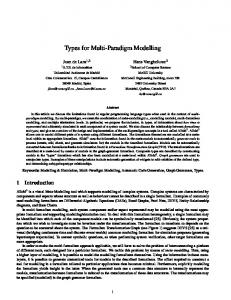
parameters by regression. They concluded that the SRK-HV model is the most useful one, providing good results and being relatively simple in structure compared to the CPA model. Figure 1 illustrates the effect of CH4 on water solubility in CO2. The lines are calculated results obtained with the SRK-HV model and the points are experimental data by Song and Kobayasi (1990).
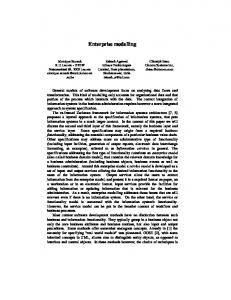
In the present work, the SRK-HV EOS was applied. However, the Huron-Vidal mixing rules are of no importance for CO2-CH4 mixture, since CO2 and CH4 are not polar molecules. Figure 2 shows the phase envelopes for the two CO2-CH4 mixtures considered in this work. They have been calculated using the Soave-Redlich-Kwong (SRK) EOS. It can be seen that the bubble and dew temperatures are affected by the mixture composition. The region close to the critical point is not included in the figure.
The SRK EOS is a cubic equation of state, i.e., third order with respect to volume and density. It is a relatively simple equation with only a few adjustable parameters and it is easily applicable for mixtures and phase-equilibrium calculations. Cubic EOS’es are in general poorly suited to describe the liquid phase, polar components, and complex mixtures. For the problem with the liquid-phase volume, the solution is to use a volume shift, which is a correction in liquid volume that is evaluated based on experimental data.
The SRK model can be cast in the form given by Reid et al. (1986): p
ai RT v bi v ( v bi ) bi ( v bi )
(10)
11
where p is pressure, T is temperature, v is the mixture molar volume, and R is the universal gas constant. The two state constants ai and bi are evaluated as follows, for each component, i, in the mixture: bi
b RT RTci 2 ; ai i a pci pci
. (11)
Herein, pci and Tci are the critical temperature and pressure, respectively, of component i. The following standard relation was applied for the parameter αi:
i 1 mi 1 Tri
; 2
where Tri
T Tci
mi i i2
(12)
where Tri is the reduced temperature and i is the acentric factor. Values for the other parameters can be found in Soave (1972) and they are summarized in Table 2. The pseudo-critical properties of a mixture of constant composition are determined using a procedure proposed by Michelsen (1980).
3
Numerical method
In this section, the numerical method employed to solve the drift-flux model is briefly presented. The equation system (1)–(3) model of Section 2 can be written in the following form: q f ( q ) 0, t x
(13) where the source terms are disregarded for simplicity, and where q is the n + 2-vector of unknowns: qi = ρmzi for i = 1,…,n,
(14)
qn+1 = αgρgug + αℓρℓuℓ,
(15)
qn+2 = αgρget,g + αℓρℓet,ℓ.
(16) 12
The model (13) can be integrated over a control volume to yield the semi-discrete formulation
d 1 q j( t ) f j 1 / 2 f j 1 / 2 dt x
. (17)
A simple way of integrating (17) in time is to use the Forward Euler method: q mj 1 q mj
t f j 1 / 2 f j 1 / 2 x
. (18)
Herein, qjm denotes the numerical approximation to the cell average of the vector of unknowns q(x,tm) in control volume j at time step m. Quantities without a time index are evaluated at time step m.
The most challenging part of solving (17) is to find an approximation to the cellinterface flux vector, fj+1/2. For an accurate numerical solution, it would be desirable to have an upwind resolution of all the waves inherent in the model (1)–(3), for instance by constructing an approximate Riemann solver of the type of Roe (1981). However, this is relatively complex, even for simpler types of drift-flux models than the one considered here (Flåtten and Munkejord, 2006). The multi-stage centred (MUSTA) scheme was formulated by Toro and coworkers (Toro, 2003; Titarev and Toro, 2005) to approach the accuracy of upwind schemes while maintaining the simplicity of centred schemes. The idea is to find a numerical approximation to the cell-interface Riemann problem by solving a simple, first-order scheme on a local grid. It was shown that in the case of linear advection, for an increasing number of pseudo-time steps on the local grid, the MUSTA flux approaches that of the Godunov method (Titarev and Toro, 2005). Titarev and Toro (2005) considered the Euler equations of single-phase flow. Munkejord et al. (2006) explored the MUSTA scheme for a drift-flux model without an energy equation.
13
Even though the present model is considerably more complex, it has the same form as the one in Munkejord et al. (2006), so the MUSTA scheme can be applied rather directly.
The scheme (18) is of first order. Second-order accuracy can, for instance, be obtained by considering the semi-discretization (17) and using the monotone upwind-centred scheme for conservation laws (MUSCL) (van Leer, 1979; Osher, 1985). More details can be found in Munkejord et al. (2006). In the following, we employ the MUSCLMUSTA scheme with two local stages and two local cells. This scheme is second order in space and time.
After each time step, the MUSTA solver returns the vector q (14)–(16) of composite variables. However, the primitive variables (pressure, temperature, gas volume fraction, phasic velocities, phasic internal energies, as well as gas and liquid mixture composition) are also needed. Due to the complex thermodynamical relations, they have to be found by iteration.
4
Pipe-depressurization example
In this section, we will consider a pipe depressurization as an example. First, we will verify that the MUSTA scheme satisfies basic criteria regarding convergence. Next, a demonstration will be made of the effect of the CO2-mixture composition. Finally, the effect of the slip law, heat transfer and wall friction will be illustrated. We consider a mixture of CO2 and methane, as mentioned in Section 1.2. The test case consists of a pipe of length 100 m, closed at x = 0 m, and with a membrane at x = 100 m, see Figure 3. Initially, the pressure is p0 = 60 bar, and the mixture is at rest, at a temperature 0.5 K 14
above its bubble point. At time t = 0, the membrane ruptures. The external pressure is pe = 30 bar, so a depressurization wave starts propagating into the fluid, which then starts flowing towards the exit. Some of the liquid evaporates, and the temperature sinks.
All the calculations presented in the following have been performed using the MUSCLMUSTA scheme with a Courant-Friedrichs-Lewy (CFL) number of 0.5. In the examples, a perfectly insulated horizontal pipe with no friction is considered (gx = Fw = Q = 0), unless otherwise stated, and the plotted data are for t = 1 s.
4.1 Grid convergence To illustrate the convergence properties of the MUSCL-MUSTA scheme, calculations have been performed on various grids ranging from 50 to 3200 cells. Here, the CO2CH4 mixture consists of 99 % CO2. Figure 4 shows the pressure, temperature, velocity and gas volume fraction plotted at t = 1 s. It can be seen that the numerical results converge as the grid is refined, and that no spurious oscillations are introduced. In this case, the 800-cell grid yields close-to-converged results, and this grid will be used for the following calculations.
The temporal variation of the volume fraction is plotted in Figure 5. The temporal variation of the other variables is analogous.
Plots such as the ones in Figure 4 are important to establish that we have, in fact, an accurate numerical solution of the governing equations (1)–(3). Without that, in future work, we cannot know whether any observed discrepancies between numerical
15
calculations and experimental data are caused by numerical errors or modelling simplifications (not counting experimental uncertainties).
4.2 Influence of mixture composition To show the influence of the mixture composition, two different mixtures have been considered, one with zCO2 = 99 % and the other with zCO2 = 95 %. Figure 6 displays results calculated at t = 1 s. The left-hand plot shows the pressure. It can be seen that the pressure-propagation speed (or mixture sonic speed) is higher for the 99 % CO2 mixture. One can also note that the mixture sonic speed is in the order of 70 m/s, which is significantly lower than the speed of sound for each of the mixture components, both in the gas and the liquid phase. The right-hand plot of Figure 6 shows the initial temperature subtracted by the final temperature. The cooling effect of evaporation is highest for the mixture with the highest CO2 content.
Models for mixture sonic speeds are discussed by Drew and Passman (1999, Section 22.2) and Evje and Flåtten (2007), albeit for simpler models than the present one.
4.3 Influence of slip relation An assumption of no slip between the phases is likely to be a somewhat coarse simplification. However, to establish which slip relation is better suited for CO2 pipe depressurizations is outside the scope of the present work. Nevertheless, as an illustration of the effect that the slip relation may have, calculations have been performed employing the Zuber–Findlay relation (8). Here, the values K = 1.07 and S = 0.216 m/s have been taken for the empirical parameters. These values have commonly been used in numerical benchmark tests (Evje and Fjelde, 2002; Baudin et al., 2005; Munkejord et al., 2006). 16
Figure 7 shows the effect of employing the Zuber–Findlay relation compared to using the no-slip assumption. This case is for the zCO2 = 99 % mixture. The right-hand plot shows the velocity. Interestingly, in the middle of the pipe, both the gas and the liquid velocity is higher than the no-slip velocity, while at the end of the pipe, the gas velocity is higher, and the liquid velocity is lower than the no-slip velocity. The left-hand plot shows that the pressure profile is also affected by the slip relation.
4.4 Influence of heat transfer In several applications, for instance calculations in long transport pipelines, heat transfer from the surroundings will play a role. In this section, the heat-transfer model (9) will be employed. For the present illustration purposes, constant inner and outer heattransfer coefficients, η and ηe, are assumed. In convective boiling of CO2, a high heattransfer coefficient can be expected (see e.g. Bredesen et al., 1997) . Here we take η = 5 kW/(m2K). Regarding the outer heat-transfer coefficient, it will be in the order of ηe = 10 W/(m2K) in air. In other circumstances, it can be higher. Further, we assume an exterior temperature of Te = 300 K. The pipe data are given in Table 3.
Calculations have been performed for the zCO2 = 99 % mixture, and Figure 8 displays a plot of the fluid temperature for outer heat-transfer coefficients, ηe, of 10, 100 and 1000 W/(m2K). A plot of the temperature without heat transfer is not shown, but it is virtually identical to the one for ηe = 10 W/(m2K). Indeed, the effect of increasing ηe to 100 W/(m2K) is minuscule, and only for 1000 W/(m2K) can one see a temperature rise near the end of the pipe. Figure 8 does not show that heat transfer will not affect the fluid temperature in general, but it does indicate that normally, a longer time span than 1 s would be needed. 17
4.5 Influence of wall friction In this section, we will test the effect of employing the Friedel (1979) model for the wall-friction force in the momentum (2) and energy equation (3). The zCO2 = 99 % mixture is considered, and Figure 9 displays a plot of the pressure (left) and velocity (right). As expected, the inclusion of the wall-friction effect reduces the velocity, but it is still as high as 60 m/s at the outlet.
5
Conclusion
We have proposed to employ a two-phase multi-component drift-flux model for the transport and depressurization of CO2 mixtures. Calculations have been performed for a CO2-CH4 mixture using the Soave-Redlich-Kwong equation of state to compute the mixture properties. The multi-stage centred (MUSTA) scheme was employed for the numerical solution of the drift-flux model and produced accurate results even for this complex model. It should be noted, however, that the accuracy of the model itself, depends on constitutive relations like the slip relation, heat-transfer model and wallfriction model, which need to be further studied for CO2-transport applications.
The present results confirm that the mixture composition influences the pressurepropagation speed and the amount of cooling exerted by depressurization. These issues should be taken into account for the design and operation of CO2 transport systems.
Acknowledgement This work was funded by SINTEF Energy Research and the project CO2 Dynamics performed under the strategic Norwegian Research programme Climit. The authors
18
acknowledge the partners; Gassco AS, StatoilHydro Petroleum AS, Vattenfall Research and Development AB, and the Research Council of Norway (189978) for support.
Thanks are due to our colleague Hailong Li for generating Figure 2.
We also thank the anonymous reviewers, whose constructive comments contributed to improving the paper.
6
References
A. Austegard, E. Solbraa, G. de Koeijer and M.J. Mølnvik, 2006. Thermodynamic models for calculating mutual solubilities in a H2O-CO2-CH4 mixture. Chem. Eng. Res. Des. 84, 781–794.
M. Baudin, C. Berthon, F. Coquel, R. Masson and Q.H. Tran, 2005. A relaxation method for two-phase flow models with hydrodynamic closure law. Numer. Math. 99, 411–440.
A. Bejan, 1993. Heat transfer. Wiley, New York, USA. ISBN 0-471-50290-1.
K.H. Bendiksen, 1984. An experimental investigation of the motion of long bubbles in inclined tubes. Int. J. Multiphase Flow, 10, 467–483.
A.M. Bredesen, A. Hafner, J. Pettersen, P. Nekså and K. Aflekt, 1997. Heat transfer and pressure drop for in-tube evaporation of CO2. International-Institute-of-Refrigeration Conference on Heat Transfer Issues in Natural Refrigerants, Maryland, USA, 6–7 November, 1997. Refrigeration Science and Technology 5, 35–49, IIR/IIF. 19
J.G. Collier and J.R. Thome, 1994. Convective boiling and condensation. Oxford University Press, Oxford, UK, third edition. ISBN 0-19-856282-9.
E. de Visser, C. Hendriks, M. Barrio, M.J. Mølnvik and G. de Koeijer, 2008. Dynamis CO2 quality recommendations. Int. J. Green. Gas Control 2, 478–484.
D.A. Drew and S.L. Passman, 1999. Theory of multicomponent fluids. Springer-Verlag, New York, USA. ISBN 0-387-98380-5.
Z. Duan, N. Møller and J.H. Weare, 1992a. An equation of state for the CH4-CO2-H2O system: I. Pure systems from 0 to 1000 °C and 0 to 8000 bar. Geochim. Cosmochim. Ac. 56, 2605–2617.
Z. Duan, N. Møller and J.H. Weare, 1992b. An equation of state for the CH4-CO2-H2O system: II. Mixtures from 50 to 1000 oC and 0 to 1000 bar. Geochim. Cosmochim. Ac. 56, 2619–2631.
S. Evje and K.K. Fjelde, 2002. Hybrid flux-splitting schemes for a two-phase flow modell. J. Comput. Phys. 175, 674–701.
S. Evje and T. Flåtten, 2006. On the wave structure of two-phase flow models. SIAM J. Appl. Math. 67, 487–511.
20
T. Flåtten and S.T. Munkejord, 2006. The approximate Riemann solver of Roe applied to a drift-flux two-phase flow model. ESAIM – Math. Model. Num. 40, 738–764.
F. França and R.T. Lahey, Jr., 1992. The use of drift-flux techniques for the analysis of horizontal two-phase flows. Int. J. Multiphase Flow, 18, 787–801.
L. Friedel, 1979. Improved friction pressure drop correlations for horizontal and vertical two phase pipe flow. Paper E2, European Two Phase Flow Group Meeting, Ispra, Italy, June 1979.
V. Henriot, C. Pauchon, P. Duchet-Suchaux and C.F. Leibovici, 1997. TACITE: Contribution of fluid composition tracing on transient multiphase flow simulation. In: Proceedings, 29th Annual Offshore Technology Conference, OTC ’97, Houston, Texas, USA, May 1997.
T. Hibiki and M. Ishii, 2002. Distribution parameter and drift velocity of drift-flux model in bubbly flow. Int. J. Heat Mass Tran. 45, 707–721.
Intergovernmental Panel on Climate Change (IPCC), 2005. IPCC Special Report on Carbon Dioxide Capture and Storage, Cambridge University Press, Cambridge, United Kingdom / New York, USA.
M. Ishii, 1977. Drift flux model and derivation of kinematic constitutive laws. In: S. Kakaç and F. Mayinger, editors, Proceedings of NATO Advanced Study Institute, 187– 208, Hemisphere.
21
H. Li, X. Ji and J. Yan, 2006. A new modification on RK EOS for gaseous CO2 and gaseous mixtures of CO2 and H2O. Int. J. Energy Res. 30, 135–148.
H. Li and J. Yan, 2006. Impacts of impurities in CO2-fluids on CO2 transport process. Proceedings of the 51st ASME Turbo Expo, vol. 4, Barcelona, Spain, May, 2006.
H. Li, J.P. Jakobsen, J. Yan, 2009, Properties of CO2 mixtures relevant for CO2 capture, transport, and storage: Review of available experimental data and theoretical models. Submitted.
M.L. Michelsen, 1980. Calculation of phase envelopes and critical points for multicomponent mixtures. Fluid Phase Equilibr. 4, 1–10.
S.T. Munkejord, S. Evje and T. Flåtten, 2006. The multi-stage centred-scheme approach applied to a drift-flux two-phase flow model. Int. J. Numer. Meth. Fluids. 52, 679–705.
D. Nieva and R.M. Barragán, 2003. HCO-TERNARY: A FORTRAN code for calculating P-V-T-X properties and liquid vapour equilibria of fluids in the system H2OCO2-CH4. Comput. Geosci. 29, 469–485.
S. Osher, 1985. Convergence of generalized MUSCL schemes. SIAM J. Numer. Anal. 22, 947–961.
22
R.C. Reid, J.M. Prausnitz, B.E. Poling, 1986. The properties of Gases and Liquids, 4th edition, McGraw-Hill.
P.L. Roe, 1981. Approximate Riemann solvers, parameter vectors, and difference schemes. J. Comput. Phys. 43, 357–372.
G.S. Soave, 1972, Equilibrium constants from modified Redlich-Kwong equation of state. Chem. Eng. Sci, 27, 6, 1197
K.Y. Song and R. Kobayashi, 1990. The water content of a CO2-rich gas mixture containing 5.31 mol% methane along three-phase and super-critical conditions. J. Chem. Eng. Data, 35, 320–322.
V.A. Titarev and E.F. Toro, 2005. MUSTA schemes for multi-dimensional hyperbolic systems: analysis and improvements. Int. J. Numer. Meth. Fluids. 49, 117–147.
E.F. Toro, 2003. Multi-stage predictor-corrector fluxes for hyperbolic equations. Isaac Newton Institute for Mathematical Sciences Preprint Series, NI03037-NPA, University of Cambridge.
B. van Leer, 1979. Towards the ultimate conservative difference scheme V. A secondorder sequel to Godunov’s method. J. Comput. Phys. 32, 101–136.
N. Zuber and J.A. Findlay, 1965. Average volumetric concentration in two-phase flow systems. J. Heat Trans. – T. ASME 87, 453–468.
23
Figure captions Figure 1: Water solubility in pure CO2 and in a CO2-CH4 mixture at 25 °C. Figure 2: Phase envelope for two CO2-CH4 mixtures, one with 99 % and one with 95 % CO2 (by weight). Figure 3: Test-case setup. Figure 4: Depressurization of a carbon dioxide-methane mixture. Convergence of the MUSCL-MUSTA scheme by grid refinement. Pressure (top left), temperature (top right), velocity (bottom left) and gas volume fraction (bottom right). Figure 5: Depressurization of a carbon dioxide-methane mixture. Temporal development of the gas volume fraction. Figure 6: Depressurization of two carbon dioxide-methane mixtures. Pressure (left) and difference between initial and final temperature (right). Figure 7: Depressurization of a carbon dioxide-methane mixture. Comparison of no slip and the Zuber–Findlay relation. Pressure (left) and velocity (right). Figure 8: Temperature for depressurization of a carbon dioxide-methane mixture. Effect of outer heat-transfer coefficient. Figure 9: Depressurization of a carbon dioxide-methane mixture. Effect of wall friction. Pressure (left) and velocity (right).
24
Table captions Table 1: Possible impurities from different industrial processes (Li et al 2009, based on IPCC 2005). Table 2: Coefficients of the Soave-Redlich-Kwong equation of state (Soave, 1972). Table 3: Pipe data.
25
yH2O(%)
Figure 1
0.5 0.45 0.4 0.35 0.3 0.25 0.2 0.15 0.1 0.05 0
pure CO2
CO2 and 5% CH4 0
20 0
40 0
60
80
P (bar)
100
120
140
Figure 2
CO2/CH4: 95/05 wt% CO2/CH4: 99/01 wt% SRK EOS
300
Temperature (K)
290
Dew Point
280 270 Bubble Point 260 250 240 25
30
35
40
45
50 55 60 Pressure (bar)
65
70
75
80
Figure 3
p0, T0, z0 0
pe, Te x L
Figure 4
60 55
285
T (K)
50 p (bar)
50 cells 100 cells 400 cells 3200 cells
290
50 cells 100 cells 400 cells 3200 cells
45
280 275
40 270
35 30 0
20
40
x (m)
60
80
100
40
60
80
100
60
80
100
x (m)
50 cells 100 cells 400 cells 3200 cells
0.8
60
0.6
αg (−)
u (m/s)
20
1
50 cells 100 cells 400 cells 3200 cells
80
40
0.4
20 0 0
265 0
0.2
20
40
x (m)
60
80
100
0 0
20
40
x (m)
Figure 5
1
0.8
g ()
0.6
0.4 t=1 s
t=0.8 s t=0.6 s t=0.4 s
0.2
0 0
t=0.2 s t=0
20
40
60 x (m)
80
100
Figure 6
0
99 % CO2 95 % CO2
55
-5
50
-10 T (K)
p (bar)
60
45
99 % CO2 95 % CO2
-15
40 -20 35 30 0
-25 20
40
60 x (m)
80
100
0
20
40
60 x (m)
80
100
Figure 7
60
No slip Zuber-Findlay (g) Zuber-Findlay (l)
No slip Zuber-Findlay
100 55 80 u (m/s)
p (bar)
50 45
40
40
20
35 30 0
60
20
40
60 x (m)
80
100
0 0
20
40
60 x (m)
80
100
Figure 8
290
ηo=10 Wm-2K-1 -2 -1 ηo=100 Wm K -2 -1 ηo=1000 Wm K
285
T (K)
280 275 270 265 0
20
40
x (m)
60
80
100
Figure 9
No friction Friedel model
No friction Friedel model
55
80
50
60 u (m/s)
p (bar)
60
45
40
40 20
35 30 0
20
40
60 x (m)
80
100
0 0
20
40
60 x (m)
80
100
Table 1
# 1 2 3 4 5
Description CO2 captured from natural gas sweetening CO2 captured from heavy oil production and upgrading CO2 captured from power plants using post-combustion capture CO2 captured from power plants using oxy-combustion capture CO2 captured from power plants using pre-combustion capture
Possible impurities CH4, amines, H2O H2S, N2, O2, CO, H2O, H2, COS, Ar, SOx, NOx N2, amines, H2O, O2, NH3 SOx, NOx N2, O2, SO2, H2S, Ar H2, CO, N2, H2S, CH4
Table 2
0.48
1.574
0.176
a
0.42748
b
0.08664
Table 3
Inner radius Thickness Thermal conductivity r (m)
δ (m)
λ (W/(m K))
0.05
0.005
43