by Using Surface-Impedance Model. Laurence Richard, Alexander I. Nosich, and Jean-Pierre Daniel. AbstractâThe results of analytical and numerical study of ...
1374
IEEE TRANSACTIONS ON ANTENNAS AND PROPAGATION, VOL. 47, NO. 8, AUGUST 1999
Letters Revisiting the Waves on a Coated Cylinder by Using Surface-Impedance Model Laurence Richard, Alexander I. Nosich, and Jean-Pierre Daniel
Abstract—The results of analytical and numerical study of the modes propagating on an impedance-surface circular cylinder are communicated. Besides the well-known axially symmetric Sommerfeld’s mode, another hybrid mode, having a single azimuthal variation, can propagate at any frequency. For a realistic cylindrical conformal antenna, the both wavenumbers are quite comparable. This may cause additional coupling between array antenna elements. Index Terms— Dielectric-coated metallic cylinder, printed antennas, surface impedance.
I. INTRODUCTION The analysis of the electromagnetic wave propagation along an imperfect infinite circular wire was first done by Sommerfeld in his pioneering paper [1]. He discovered that a TM mode E01 , having no azimuthal field dependence, can propagate at any frequency. Cylinders have been studied in view of waveguide and antenna applications since the 1950’s [2]–[6]. A new interest to the dielectriccoated cylinder has appeared recently in concern of the radiation of conformal printed antenna arrays [7]. The efficiency of radiation, input impedance, and the far-field radiation pattern are influenced by the guided and leaky modes of the substrate. As the thickness of the coating is normally small, it can be approximated by an impedance-type boundary condition [5]. As we demonstrate, besides the well-known E01 mode, another one (HE11 ) is able to propagate with a nearly equal wavenumber. II. DISPERSION EQUATIONS The modal analysis of the surface waves propagating along an impedance wire (Fig. 1) as a traveling wave exp(i!t 0 ihz ) is based on the eigenvalue problem, in terms of the wavenumber h for the set of homogeneous Maxwell equations with the boundary condition
~ tan E
=
~ tan ]; Z0 Zs [^nout 2 H
r=a
(1)
and a request to the field to decay in the cross-sectional plane. Here, Zs is the normalized surface impedance. Due to the circular symmetry, the modes having m = 0; 1; 2; 1 1 1 azimuthal variations can be considered separately that results in the following dispersion equations:
0
2 0 (ka ) [ Km (ka ) iZs Km (ka )][ Km (ka ) 0 1 0 2 iZs Km (ka )] + m (1 + 2 )[Km (ka )]2 = 0
0
(2)
where Km (1) are the modified Bessel functions of the second kind, k is the free-space wavenumber, and = (h2 =k2 0 1) . Manuscript received July 1996. This work was supported in part by the Conseil R´egional de Bretagne, France. L. Richard and J.-P. Daniel are with the Laboratoire Antennes et R´eseaux, URA 834 CNRS, Universit´e de Rennes 1, Rennes, 35042 France. A. I. Nosich is with the Institute of Radiophysics and Electronics, Ukrainian Academy of Sciences, Kharkov, 310085, Ukraine. Publisher Item Identifier S 0018-926X(99)07970-3.
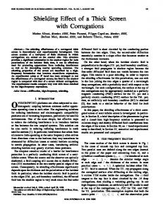
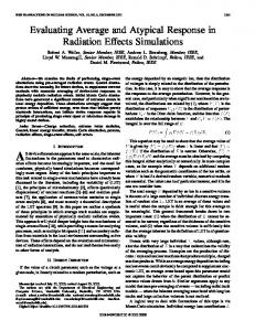
Fig. 1. Dispersion of impedance-wire modes.
If m = 0, (2) splits to two separate ones, for axially-symmetric TM and TE modes. Following [1] and using one-term approximation for K0 (ka ), one finds that if ka � 1 there is a root corresponding to the mode E01
h=k = f1 + i2Zs [ka ln(0ikaZs )]01g1=2 :
(3)
If m 6= 0, (2) has a more complicated structure because nonsymmetric modes are hybrid ones, with all six field components present. The most interesting is the case m = 1, as in this mode family there is another principal mode having no cutoff. By using two terms of the series expansion of K1 (ka ) (one is not enough!), we arrive at the following expression valid if ka � 1:
h k
=
1+
4
2 exp ( ka)
0 (ka1 )2 0 kai
Zs +
1
Zs
1=2
(4)
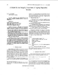
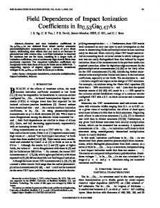
for the wavenumber of the hybrid HE11 mode, where = 1 1 1. If contrary ka � 1, then for the both modes the wavenumbers tend to h=k = (1 0 Zs2 )1=2 . In the case of a constant lossless impedance Zs = iZ , Z > 0, the results of numerical solution of (2) by the Muller method are shown in Fig. 1. The dispersion curves agree with (3) and (4) for small ka < 1 and show almost the same value after ka = 5. Thus, Sommerfeld’s mode strongly dominates in the thin-wire propagation case studied in [1]. Probably this explains the reason of overlooking the mode HE11 , for example, in [7]. However, in the conformal antenna geometries normally ka > 2 that makes thin-wire approximation inapplicable. In Figs. 2 and 3, we present the integrated numerical data on the E01 and HE11 modes in the form of equal-value curves of h=k in the plane of parameters ka and Z . Except for the range ka � 0:5, the two principal modes are in strong competition. 1:7811
0018–926X/99$10.00 1999 IEEE
IEEE TRANSACTIONS ON ANTENNAS AND PROPAGATION, VOL. 47, NO. 8, AUGUST 1999
Fig. 2. Wavenumber relief for the Sommerfeld’s mode.
1375
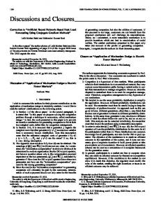
Fig. 4. Dispersion of modes on a coated cylinder.
of the higher order modes, which have nonzero cutoffs. The nearest of them, denoted as HE12 , is also shown. IV. CONCLUSION By using a simple model, we have shown that in a realistic cylindrical antenna geometry, not one but two different guided modes E01 and HE11 can be excited whatever thin is the substrate. Both modes should be taken into account in a full-wave analysis of a conformal antenna performance. Actually, the hybrid mode, which we reported here, is similar to the so-called “dipole” principal mode of a dielectric fiber [6]. Dispersion equation for the hybrid modes on a dielectric-coated metallic cylinder has been known before [6], but no numerical results were given, except for [4]. In [8], an erroneous assertion on the HE11 low-frequency cutoff was found. A correct conclusion that here this mode has no cutoff seems to be met only in [4] and [9]. Zero cutoff frequency means that a mode can propagate however thin the substrate. This fact has a fundamental nature and can be studied by the surface-impedance approach in spite of the approximate character of (5). Our final remark is that arbitrary excitation will launch two modes HE11 having the fields of orthogonal symmetry.
Fig. 3. Wavenumber relief for the “dipole” mode.
III. DIELECTRIC COATING ON A METAL CYLINDER
REFERENCES
In fact, the surface-impedance model serves as a convenient instrument to simplify the analysis of perfect metal conductors covered with a thin dielectric layer [5]. This implies that the actual value of impedance is given as
[1] A. Sommerfeld, Electrodynamics. New York: Academic, 1952, p. 178; Annalen der Physik, vol. 67, pp. 233–290, 1899 (original). [2] G. Goubau, “Surface waves and their application to transmission lines,” J. Appl. Phys., vol. 21, no. 11, pp. 1119–1128, 1950. [3] N. C. Wenger, “The launching of surface waves on an axial-cylindrical reactive surface,” IEEE Trans. Antennas Propagat., vol. AP-13, pp. 126–134, Jan. 1965. [4] J. Y. Savard, “Higher-order cylindrical surface-wave modes,” IEEE Trans. Microwave Theory Tech., vol. MTT-15, pp. 151–155, Mar. 1967. [5] J. R. Wait, Electromagnetic Radiation from Cylindrical Structures. London, U.K.: Pergamon, 1959. [6] C. H. Walter, Traveling Wave Antennas. New York: Dover, 1970, pp. 217–225. [7] G. Gottwald and W. Wiesbeck, “Radiation efficiency of conformal microstrip antennas on cylindrical surfaces,” in IEEE AP-S Symp. Dig., Newport Beach, CA, June 1995, vol. 4, pp. 1780–1783. [8] W. Hersch, “The surface-wave aerial,” Monograph 363 E; Proc. Inst. Elect. Eng., vol. 107, pt. C, Feb. 1960. [9] L. A. Vainshtein, Electromagnetic Waves. Moscow, Russia: Radio i Svyaz, 1988, p. 240 (in Russian).
01=2 tan[kd(�r )1=2]
Zs = i(�r )
(5)
where d and �r are the thickness and the dielectric constant of the layer. The domain of the better accuracy of (5) is normally associated with �r � 10 [5] and a realistic substrate thickness is around 1 mm. In Fig. 4, we present the dispersion curves of the principal modes on a dielectric-coated cylinder. Due to the frequency-dependent behavior of (5), now both modes have the wavenumbers tending to k at the lower frequencies, although the E01 mode is strongly dominant. However, if ka is slightly greater, the both modes propagate with nearly equal wavenumbers. A known defect of the surface-impedance model is that (5) may turn to infinity if the substrate is assumed lossless. However, this model enables one to simulate the presence