Jan 15, 2009 ... Q1: Offshore Pipeline Design Basis and Addendum. Q2: Onshore Pipeline ...
Safety Review. Q9: Onshore Hydrostatic Pressure Testing Report ...
Appendix Q Pipeline Design Information Q1: Q2: Q3: Q4: Q5: Q6: Q7: Q8: Q9:
Offshore Pipeline Design Basis and Addendum Onshore Pipeline Design Basis Landfall Valve Installation Design Overview Design Code Review Onshore Pipeline Section Pipeline Integrity Management Scheme (PIMS) Corrib Pipeline Internal Corrosion Rate Assessment Quantified Risk Analysis Recommendations arising from Independent Safety Review Onshore Hydrostatic Pressure Testing Report
Appendix Q1
Offshore Pipeline Design Basis and Addendum
Shell E&P Ireland Limited CORRIB FIELD DEVELOPMENT PROJECT REPORT
PROJECT No.
052377 REF
ADDENDUM NO 1 TO OFFSHORE DESIGN BASIS
CTR 336
No OF SHEETS
3 DOCUMENT No
OFFICE CODE
PROJECT No
AREA
DIS
TYPE
NUMBER
05
2377
01
P
3
027
03
15/01/09
Revised for Planning Application
JG
GSW
JG
02
07/03/08
For Planning Application
CW
JG
JG
01
13/02/08
For Review by SEPIL
CW
JG
JG
REV
DATE
BY
CHK
DESCRIPTION
ENG
PM
CLIENT
Corrib Field Development Project Offshore Design Basis Addendum No 1
Reference Document: OFFSHORE DESIGN BASIS J P Kenny Document 05-2102-01-P-3-100 Rev 04 dated 10/5/02 issued as Allseas Document No.: 8820/D100-01
ADDENDUM No 1 General J P Kenny Document 05-2102-01-P-3-100 Rev 04 dated 10/5/02 (also issued as Allseas Document No: 8820/D100-01) presented the Design Basis for the Corrib Offshore Pipeline. Since that issue a number of statements or items of data have changed and the purpose of this Addendum No 1 is record and document these changes as at March 2008. The original document remains a valid basis for design of the offshore section of the Corrib export pipeline. None of the changes identified below materially affect the original design basis for the offshore pipeline. A copy of the original Offshore Design Basis is attached following this Addendum No 1 for reference purposes. Item
Section
Description
1.
1.1
Shell E&P Ireland Ltd has replaced Enterprise Energy Ireland Ltd as the owner of the Corrib Field.
2.
1.2
Manifold tie-in is no longer part of the Allseas scope. Allseas subcontract with Stolt Offshore is closed.
3.
2.1
Distance from landfall to water outfall diffuser is more than 12km. This change has been incorporated in the design (see section 4.6) but the update in this section was omitted in error.
4.
2.2
Landfall location has been revised. Refer drawing 05-2377-01-P-0-007 DG103 Gas Export Pipeline Overall Route Layout, latest revision.
5.
3.1
The system for Regulatory Approvals has been substantially changed. The prevailing system for Regulatory Approvals will be applied
6.
3.2
A newer revision of DNV OS F-101 has since been issued (2007), but the offshore pipeline as designed is, as stated, to the 2000 issue.
7.
4.6
The water outfall pipeline will only transport treated run-off water from the Terminal. Produced water from the Terminal will be transported via the Umbilical to the subsea facilities.
8.
8.1
Delete first paragraph and replace with; This section defines the approaches to be taken to detailed design of the sealine. The extent of the sealine is taken as being from the connection with the tie-in spool at the upstream side of the PLEM to the tie-in weld with the Landfall Valve Installation. The piggy-backed umbilical conduit and outfall pipe are also included
Page 2 of 3 App Q1_addendum
Corrib Field Development Project Offshore Design Basis Addendum No 1 Item 9.
Section 8.8
Description Delete second paragraph and replace with following two paragraphs; The interface between Offshore pipeline and the Onshore pipeline is the Landfall Valve Installation system. The interface between the Offshore pipeline and the Landfall Valve Installation is at the upstream tie-in weld. END OF ADDENDUM
Page 3 of 3 App Q1_addendum
Allseas Construction Contractors SA CORRIB FIELD DEVELOPMENT PROJECT
PROJECT No.
052102.01 REF
OFFSHORE DESIGN BASIS No OF SHEETS
22 DOCUMENT No
OFFICE CODE
PROJECT No
AREA
DIS
TYPE
NUMBER
05
2102
01
P
3
100
ALLSEAS DOCUMENT NO.: 8820/D100-01
04
10/05/02
Re-approved for Design
CW
WAB
CW
MG
GD
03
31/01/02
Approved for Design
SMR
CW
CW
SMR
GD
02
24/10/01
Issued for Approval
CW
CS
CW
MG
01
10/08/01
Issued for Comment
CW
IK
CW
MG
REV
DATE
BY
CHK
ENG
PM
DESCRIPTION
CLIENT
CORRIB FIELD DEVELOPMENT PROJECT
Offshore Design Basis
Document Comment Sheet Date of Review:
Reviewed by:
Page Response by:
Lead Engineer:
of
Project Engineer:
Areas of Particular Concern:
Review Finding
Project Response
Distribution : Project File, Lead Engineer, Project Engineer Manager, Project Manager
j:\mdr0470\rp\rp0027_eis 2009 reapplication\print folder only eis feb 2009 - print folder only\appendices\appendix q (technical documentation)\pipeline design information\appendix q1 offshore pipeline design basis (and cover sheet)\q1_offshore design.doc
Page 2 of 22
2102-01-P-3-100 Rev04
CORRIB FIELD DEVELOPMENT PROJECT
Offshore Design Basis TABLE OF CONTENTS 1
INTRODUCTION............................................................................................................................. 4 1.1 1.2 1.3
2
FIELD DEVELOPMENT ................................................................................................................. 5 2.1 2.2 2.3
3
General ............................................................................................................................. 19 Pelagic Trawling .............................................................................................................. 19
DESIGN OF SEALINE.................................................................................................................. 20 8.1 8.2 8.3 8.4 8.5 8.6 8.7 8.8 8.9 8.10 8.11 8.12
9
General ............................................................................................................................. 17 Overview........................................................................................................................... 17 Pipeline Route.................................................................................................................. 17
FISHING ACTIVITIES................................................................................................................... 19 7.1 7.2
8
General ............................................................................................................................. 15 Bathymetry ....................................................................................................................... 15 Waves & Currents............................................................................................................ 15 Seawater ........................................................................................................................... 16
SEABED ....................................................................................................................................... 17 6.1 6.2 6.3
7
General ............................................................................................................................... 9 Reservoir Conditions ........................................................................................................ 9 Production Data................................................................................................................. 9 Product Details ................................................................................................................ 10 Produced Water ............................................................................................................... 12 Water Outfall Pipeline ..................................................................................................... 14 Umbilical Conduit ............................................................................................................ 14 Pigging.............................................................................................................................. 14
ENVIRONMENTAL DATA............................................................................................................ 15 5.1 5.2 5.3 5.4
6
General ............................................................................................................................... 8 Primary Codes ................................................................................................................... 8
OPERATIONAL PARAMETERS.................................................................................................... 9 4.1 4.2 4.3 4.4 4.5 4.6 4.7 4.8
5
General ............................................................................................................................... 5 Locations............................................................................................................................ 5 Infield Configuration ......................................................................................................... 6
CODES AND STANDARDS........................................................................................................... 8 3.1 3.2
4
General ............................................................................................................................... 4 Objectives........................................................................................................................... 4 Abbreviations..................................................................................................................... 4
General ............................................................................................................................. 20 Routing ............................................................................................................................. 20 Wall Thickness................................................................................................................. 20 Stability............................................................................................................................. 20 Mechanical Protection .................................................................................................... 20 Corrosion Protection & Monitoring ............................................................................... 20 Freespans......................................................................................................................... 21 Landfall ............................................................................................................................. 21 Water Outfall Pipeline ..................................................................................................... 21 Umbilical Sleeve .............................................................................................................. 21 PLEM................................................................................................................................. 21 Manifold Tie-in Spool ...................................................................................................... 21
REFERENCES.............................................................................................................................. 22
j:\mdr0470\rp\rp0027_eis 2009 reapplication\print folder only eis feb 2009 - print folder only\appendices\appendix q (technical documentation)\pipeline design information\appendix q1 offshore pipeline design basis (and cover sheet)\q1_offshore design.doc
Page 3 of 22
2102-01-P-3-100 Rev04
CORRIB FIELD DEVELOPMENT PROJECT
Offshore Design Basis 1
INTRODUCTION
1.1
General JP Kenny Ltd. has been contracted by Allseas Construction Contractors SA to prepare the detailed design of the pipeline system for the Corrib Field development Project. Corrib, being developed by Enterprise Energy Ireland Ltd, is a gas field located in 350 m of water some 60 to 65 km off the County Mayo coastline. The field will be developed as a longrange subsea tieback to an onshore facility. The gas will then be treated to meet the defined gas specification before onward transportation to the Bord Gais Eireann (BGE) grid via a new cross-country pipeline. The subsea facilities will consist of a manifold with cluster wells, together with a number of satellite wells. The pipeline system comprises flexible flowlines from the satellite wells to the manifold, and an export line to shore. This 83km 20-inch subsea pipeline from the manifold makes a landfall at Broadhaven Bay in County Mayo, and thence a further 9km onshore pipeline leads to the terminal. An electro-hydraulic umbilical system will run parallel to the pipeline system, and a water outfall pipeline will also run from the terminal to a diffuser some distance offshore.
1.2
Objectives The purpose of this document is to collate all the basic design data to be used for the detailed design of the offshore section of the Corrib pipeline system, and the approach to be used for each aspect of the work is also briefly outlined. Design data for the infield and onshore elements is covered in separate documents (Refs 8 & 9). As further data or constraints become available during the project, this document will be revised to incorporate such requirements, but results and conclusions from engineering of the pipeline system will not be addressed. Note that although the engineering covered by this document covers the offshore pipeline system, work associated with the tie-in spool at the manifold has been subcontracted by Allseas to Stolt Offshore. This is addressed within the infield facilities.
1.3
Abbreviations BGE
-
Bord Gais Eireann
DTM
-
digital terrain model
EEI
-
Enterprise Energy Ireland Ltd
ETRF -
European Terrestrial Reference Frame
FEED -
front end engineering design
JPK
-
JP Kenny Limited
KP
-
kilometre point
LAT
-
lowest astronomical tide
PLEM -
pipeline end manifold
SWL
-
still water level
WGS
-
World Geodetic System
UTM
-
Universal Transverse Mercator
j:\mdr0470\rp\rp0027_eis 2009 reapplication\print folder only eis feb 2009 - print folder only\appendices\appendix q (technical documentation)\pipeline design information\appendix q1 offshore pipeline design basis (and cover sheet)\q1_offshore design.doc
Page 4 of 22
2102-01-P-3-100 Rev04
CORRIB FIELD DEVELOPMENT PROJECT
Offshore Design Basis 2
FIELD DEVELOPMENT
2.1
General The Corrib Field is a Triassic gas reservoir located in the Slyne Basin. It contains a very dry sweet gas with an expected condensate yield of less than 0.5 bbls/ mmscf, 0.3% CO2 and no H2S. Given the water depth and the hostile nature of the environment at Corrib together with the dry nature of the gas and the high well productivity, Corrib will be developed as a long-range subsea tieback to shore. The gas will then be treated to meet the defined gas specification before onward transportation to the Bord Gais Eireann (BGE) grid via a new cross-country pipeline. Whilst field life is expected to be in the region of 15 to 20 years, the design life for the manifold, main sealine, umbilical, onshore pipeline and terminal will be 30 years. The Base Case subsea configuration comprises an 8-well manifold providing a commingling facility for five cluster wells and two satellite wells. A spare connection is available for one additional well. The facility for further wells is provided via tie-in to the upstream end of the manifold header. The system comprises the following main components: x
Wellhead and completion systems
x
Subsea tree systems, including flowbases and protection structures
x
Manifold with temporary subsea pig launcher
x
Subsea production control system, including onshore control equipment, subsea control modules, and subsea distribution unit complete with support and protection structure
x
Main umbilical, onshore and offshore, together with umbilical jumpers and infield umbilicals
x
Well jumpers and infield flowlines
x
Sealine, from PLEM and tie-in spool to manifold, via landfall to Terminal
x
Water outfall pipeline from Terminal, via the landfall to a diffuser approximately 6km offshore
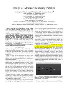
The Figure 2-1. 2.2
overall
pipeline
layout
is
illustrated
in
Locations The location of the Corrib field, 60 to 65 km off the County Mayo coastline, is illustrated in Figure 2-1 and is summarised below. Its general location is classified as West of Ireland, occupying Blocks 18/20 and 18/25. Coordinates are presented in Table 2-1. Table 2-1
Key Coordinates
Geographical
Field centre Landfall
Grid
Spheroid
Latitude
Longitude
Easting
Northing
Projection
54o 20' 20” N
11o 03' 27” W
366 250
6 023 200
UTM zone 29
WGS84
81 540
338 730
Irish National
Airy Modified
o
'
54 17 01” N
o
'
9 49 09” W
j:\mdr0470\rp\rp0027_eis 2009 reapplication\print folder only eis feb 2009 - print folder only\appendices\appendix q (technical documentation)\pipeline design information\appendix q1 offshore pipeline design basis (and cover sheet)\q1_offshore design.doc
Page 5 of 22
2102-01-P-3-100 Rev04
CORRIB FIELD DEVELOPMENT PROJECT
Offshore Design Basis Note that the exact landfall location may be revised during detailed design. Field centre is the approximate location of the well cluster at the Main Drill Centre, and will depend on the final configuration of the cluster. The offshore engineering work is to be carried out in terms of the ETRF89 geodetic reference frame, which for all practical purposes can be assumed to be based on WGS84. The landfall and onshore parts of the offshore pipelines will be designed using the Irish National Grid (1975), which is based on the Airy Modified Spheroid. At the landfall, where there is an interface between onshore & offshore systems, co-ordinates will be shown in both systems. Coordinates of existing wells are listed in Table 2-2. Additional wells are planned at the Main Drill Centre. Table 2-2
2.3
Well ID
Location
18/20-2z
Well Locations UTM coordinate Easting
Northing
Main Drill Centre
366 242.2
6 023 184.5
18/20-4
Main Drill Centre
366 253.1
6 023 158.8
18/20-3
NE satellite
367 558.5
6 024 112.7
18/25-3
SW daisy chain
365 302.0
6 021 077.0
18/25-1
SE spur
366 753.6
6 020 972.2
Infield Configuration At the Main Drill Centre, a total of five wells will be clustered around the manifold, connected by flowline and umbilical jumpers. Infield flowlines and umbilicals will connect the two satellite wells identified in Table 2-2 to the central manifold. Further infield lines will link the spur well, 18/25-1, in a daisy-chain configuration via the 18/25-3 satellite.
j:\mdr0470\rp\rp0027_eis 2009 reapplication\print folder only eis feb 2009 - print folder only\appendices\appendix q (technical documentation)\pipeline design information\appendix q1 offshore pipeline design basis (and cover sheet)\q1_offshore design.doc
Page 6 of 22
2102-01-P-3-100 Rev04
j:\mdr0470\rp\rp0027_eis 2009 reapplication\print folder only - eis feb 2009 - print folder only\appendices\appendix q (technical documentation)\pipeline design information\appendix q1 offshore pipeline design basis (and cover sheet)\q1_offshore design.doc
Page 7 of 22
Figure 2-1 Pipeline Route
Offshore Design Basis
CORRIB FIELD DEVELOPMENT PROJECT
2102-01-P-3-100 Rev04
CORRIB FIELD DEVELOPMENT PROJECT
Offshore Design Basis 3
CODES AND STANDARDS
3.1
General The pipeline system shall comply with the prevailing legislation applicable to the planning, design, construction, testing, commissioning and operation of pipelines in the Republic of Ireland. The latest editions of all regulations shall be applied, including revisions and addenda. The pipeline system from the wells to the terminal is to be classified as an upstream pipeline under the Gas (Interim) (Regulation) Act 2001. Enterprise Energy Ireland are applying for consent under section 40 of the Gas Acts 1976 to 2001 (as amended by the Gas (Interim) (Regulation) Act 2001 section 9(1)(b) ) from the Department of the Marine and Natural Resources to construct and operate an upstream pipeline, which includes both the offshore and onshore elements.
3.2
Primary Codes The primary code for the design, construction, testing, commissioning and operation of the offshore pipelines is: DnV OS-F101, Submarine Pipeline Systems (“DnV 2000”). Where this primary code is non-specific or ambiguous reference shall be made to relevant alternatives, according to good industry practice.
Q1_Offshore Design
Page 8 of 22
2102-01-P-3-100 Rev04
CORRIB FIELD DEVELOPMENT PROJECT
Offshore Design Basis 4
OPERATIONAL PARAMETERS
4.1
General This section details the operating conditions of the pipeline. Data is all taken from the EEI Project Basis of Design (Ref 7), unless noted otherwise
4.2
Reservoir Conditions Table 4-1
4.3
Initial Reservoir Conditions
Parameter
Value
Mean Depth
3500 m TVDSS
Pressure
401 bara
Temperature
112 qC
Production Data Design values for flowrates, pressures and temperatures are given in the following tables. The facilities shall be capable of the following: x
ramp down by 50% of daily flowrate in six (6) hours
x
ramp-up from turn down at 50% to 100 % of daily flowrate in six (6) hours
x
ramp-up from shut down to 100% of daily flowrate within 24 hours.
x
turn down to 20% of daily flowrate or 25MMSCFD whichever is greater
Design pressures and temperatures are given in Table 4-2 and Table 4-3. During the design life of the field, both flowrates and pressures will decline, and details are given in Table 4-4. These profiles will be used for determination of corrosion allowance, but will not be considered with respect to base wall thickness. Pipeline design pressure matches wellhead shut-in pressure. Pipeline operating pressure will normally not exceed 150 bara. Table 4-2
Pressures
Parameter
Pressure
Wellhead Shut-in
345 bara
Flowing Wellhead (max)
272 bara
Pipeline Design Pressure
345 bara
Table 4-3
Q1_Offshore Design
Temperatures
Parameter
Temperature
Flowing Wellhead (initial)
61 qC
Pipeline Inlet (design)
74 qC
Page 9 of 22
2102-01-P-3-100 Rev04
CORRIB FIELD DEVELOPMENT PROJECT
Offshore Design Basis Table 4-4
Sealine Production Profile Pressure (barg)
Production Rate (mmscfd)
Manifold *
Terminal
nd
350
223
110
rd
350
211
110
1
th
4
350
187
110
2
1st
350
166
110
2
nd
350
154
110
rd
332
138
110
th
350
161
110
st
350
148
94
nd
332
134
110
rd
311
131
89
4
289
107
66
5
229
94
64
6
185
83
61
7
155
74
57
8
132
67
51
9
114
60
46
10
100
54
39
11
84
47
33
12
74
41
28
13
67
36
22
14
66
27
14
15
48
25
12
16
35
23
10
17
29
22
9
18
25
22
7
Time Yr 1 1
2 2 3 3 3
Qtr 2
3
2
3
4
1 2
3
Note: 4.4
Manifold pressure is assumed to be available pressure (eg max FWHP), and not imposed as pipeline inlet condition. Product Details Although test data is available from five Corrib wells, for process simulation and pipeline design purposes, the properties given in the following tables shall be used. Table 4-5 Parameter
Product Properties Well 18/ 25-1
18/20-3
18/ 20-4
Relative Density (Air=1)
0.587
0.589
0.586
Average MW (g/mole)
17.0
17.0
17.0
Q1_Offshore Design
Page 10 of 22
2102-01-P-3-100 Rev04
CORRIB FIELD DEVELOPMENT PROJECT
Offshore Design Basis
Table 4-6
Product Analysis Well
Component
18/25-1
18/20-3
18/20-3
18/20-4
Bottom Hole Gas Sample 4594-S1-F
Bottomhole Sample 1439-M1-F
Wellhead Sample 0374-M1-F
Wellhead Sample 4262-M1-F
Mole %
Wt %
Mole %
Wt %
Mole %
Wt %
Mole %
Wt %
Hydrogen
0.000
0.000
0.000
0.00
0.00
0.00
0.00
0.00
Hydrogen Sulphide
0.000
0.00
0.000
0.000
0.000
0.000
0.000
0.000
Carbon Dioxide
0.321
0.832
0.258
0.664
0.251
0.646
0.261
0.676
Nitrogen
2.738
4.518
2.644
4.338
2.658
4.359
2.791
4.601
Methane
93.734
88.568
93.706
88.032
93.639
87.951
93.683
88.446
Ethane
2.947
5.219
3.028
5.334
3.072
5.408
2.968
5.253
Propane
0.144
0.374
0.161
0.415
0.159
0.410
0.159
0.412
i-Butane
0.049
0.168
0.057
0.195
0.056
0.190
0.055
0.188
n-Butane
0.021
0.071
0.021
0.073
0.022
0.073
0.022
0.075
i-Pentane
0.020
0.086
0.023
0.098
0.023
0.097
0.022
0.092
n-Pentane
0.002
0.008
0.003
0.011
0.003
0.011
0.003
0.014
Hexanes
0.012
0.062
0.014
0.073
0.015
0.075
0.013
0.066
Me-Cyclo-pentane
0.001
0.005
Benzene
0.001
0.005
Cyclo-hexane
0.000
0.002
Heptanes
0.006
0.029
0.011
0.064
0.031
0.180
0.009
0.053
Me-Cyclo-hexane
0.001
0.004
Toluene
0.001
0.007
Octanes
0.000
0.010
0.015
0.102
0.022
0.150
0.005
0.032
Ethyl-benzene
0.000
0.002
Meta/ Para-xylene
0.000
0.003
Ortho-xylene
0.000
0.002
Nonanes
0.000
0.001
0.008
0.063
0.011
0.084
0.003
0.019
Tri-Me-benzene
0.000
0.000
Decanes
0.001
0.009
0.007
0.058
0.010
0.079
0.002
0.014
Undecanes
0.001
0.015
0.006
0.053
0.008
0.070
0.001
0.013
0.039
0.427
0.020
0.218
0.003
0.046
100.0
100.00
100.0
100.0
100.0
100.0
Dodecane plus Total
Q1_Offshore Design
100.0
100.0
Page 11 of 22
2102-01-P-3-100 Rev04
CORRIB FIELD DEVELOPMENT PROJECT
Offshore Design Basis 4.5
Produced Water Water cut will vary during the design life, as detailed in Table 4-7. Properties of condensing water are as given in Table 4-8 and Table 4-9. No aquifer water was detected in well testing, but properties for the Avonmore (27/5-1) aquifer are given in Table 4-10 and Table 4-11.
Table 4-7
Water Cut
Field Life Stage
Water Content
Early
1.1 bbl/mmscfd
Late
2.6 bbl/mmscfd
Table 4-8 Well 18/20-2z
Condensing Water Analysis Well 18/25-1
Cations (mg/l)
Well 18/20-2z
Well 18/25-1
Additional Elements (mg/l)
Sodium
47
1480
Boron
0.43
2.1
Potassium
1.4
58
Aluminium