F. SALMASI, M. T. SATTARI, M. PAL
Research Article
Turk J Agric For 36 (2012) 95-106 © TÜBİTAK doi:10.3906/tar-1011-1506
Application of data mining on evaluation of energy dissipation over low gabion-stepped weir
Farzin SALMASI1, Mohammad Taghi SATTARI1,*, Mahesh PAL2 1
Water Engineering Department, Faculty of Agriculture, University of Tabriz, Tabriz - IRAN
2
Department of Civil Engineering, National Institute of Technology, Kurukshetra, 36119, Haryana - INDIA
Received: 25.11.2010
Abstract: Results of a study designed to examine the behavior of gabion-stepped weirs for energy dissipation are presented in this paper. Laboratory tests were conducted with 8 physical models consisting of 3 different porosities (38%, 40%, and 42%) and 2 slopes (1:1 and 1:2). An iron plate was also placed on each horizontal and vertical step to study and classify the effect of step porosity on the energy dissipation rate. A decision tree technique was used to derive if-then rules in order to classify the energy dissipation through the weir models. Results from this study suggest that a decision tree model has an accuracy of 85% in predicting the energy dissipation through a gabion-stepped weir using different attributes. The results demonstrate that the decision tree technique can be used as a reasonable method for classification of different parameters involved in energy dissipation through a gabion-stepped weir, and it can effectively identify the influence of various parameters on energy dissipation. Key words: Decision tree, energy dissipation, gabion, porosity, slope, stepped weir
Introduction Gabion weirs are commonly used in water structures such as small earth dams, soil conservation works, retaining walls, river training works at bends, and intake. Gabion weirs are easy to build, structurally stable, flexible, and resistant to water loads. This structure is an economic alternative to other types of weirs in areas in which stone is readily available. A stepped weir is a type of weir that can also be made in gabions. In gabion structures, the flow of water through the pervious body of a weir is an important characteristic, one which also makes flow conditions more complex. Gabions consist of porous media enclosed within a wire mesh grid. At low discharges,
flow occurs only through the body of the weir. With increasing discharge, flow occurs both through the body (gabion porous media) and over the stepped weirs. This suggests that energy dissipation in a gabion-stepped weir may be higher than that of a rigid (impervious) stepped weir due to both overflow resistance from the steps and the body flow. Studies by Peyras et al. (1992) and Chinnarasri et al. (2008) suggest that changes in material porosity and weir slope affect the energy dissipation rate in a gabionstepped weir. Most of the research related to the design of stepped weirs or spillways concerns rigid structures in large dams. Stepped weirs are usually made from
* E-mail:
[email protected]
95
Application of data mining on evaluation of energy dissipation over low gabion-stepped weir
simple or roller-compacted concrete (RCC). The literature suggests that only a few studies have been carried out on the use of gabion-stepped weirs (Peyras et al. 1992; Chinnarasri et al. 2008). Modern stepped spillways are typically designed for large discharge capacities corresponding to a skimming flow regime in which flow resistance derives predominantly from drag, and flow is nonaerated at the upstream ends. Stepped channels have been used for more than 3500 years. Greek engineers were possibly the first to design an overflow stepped spillway (Gonzalez et al. 2008). The stepped design increases the rate of energy dissipation on the chute above the steps and reduces the size of the downstream energy dissipater. During the last 3 decades, researchers on the hydraulics of stepped spillways have been very active (Chanson 2001). In a given stepped chute, water flows as a succession of free-falling nappes (nappe flow regime) at small discharges. For an intermediate range of flow rates, a transition flow regime is also observed (Chanson 2006; Toombes and Chanson 2008). Most prototype spillways operate at large discharges per unit width, and the water skims as a coherent stream over a pseudobottom formed by step edges. The skimming flows are characterized by significant losses and momentum transfers from the main stream to the recirculation zones (Rajaratnam 1990; Chanson 2006). Peyras et al. (1992) performed an experimental study using a stepped gabion weir and suggested that it improved energy dissipation. Traditionally, modeling studies in engineering applications are based on a good understanding of the underlying physical model processes in hydraulics laboratories. In addition to physical models, numerical models, which are mathematical representations of physical models, are often used. Governing equations can be solved by using finitedifference, finite-element, or other schemes with a computer, and results, normally water levels or discharges, are presented to decision makers. The observed data are used for the model calibration. Such models are generally referred to as physically based, simulation, or process models. On the other hand, a data-driven model of a system is defined as a model connecting the system state variables (input, internal, and output variables) with only limited knowledge of the physical behavior of a system. 96
The aim of this work was to study the energy dissipation capabilities of 4 different types of gabionstepped weirs under laboratory conditions and to derive a suitable empirical relation for each case. Furthermore, recalling the usefulness of a tree-based classification/regression approach in various water resource applications, a univariate decision tree method was used to classify all 4 types of weirs based on their energy dissipation characteristics. The use of a decision tree classifier in this study was supported by the fact that these classifiers provide accuracy comparable to that achieved by a neural network classifier (Pal and Mather 2003; Foody and Mathur 2004). Other reasons for using a decision tree classifier are the small computation costs involved, the easy interpretation of the model produced after training to derive if-then rules, and the fact that decision tree classifiers require no user-defined parameters. Materials and methods Physical models Experiments were conducted at the Department of Water Engineering of the University of Tabriz, Iran. A flume 10 m in length, 0.25 m in width, and 0.5 m in height with a maximum flow rate of 50 L s–1 was used for the experiments. The weir models used were constructed with 3 steps, each measuring 10 cm in height. A total of 267 tests were conducted with 2 different slopes, 3 different porosities, and varying flow rates. The slopes used were 1:1 and 1:2 (v:h). Based on the sieve analyses, gabions were filled with different stone sizes (16-19 mm, 19-25 mm, and 25-38 mm) to achieve 3 porosities measured as 38%, 40%, and 42%, respectively. Peyras at al. (1992) used 30-45 mm stone in a gabion mesh. Chinnarasri et al. (2008) used 3 stone types in a gabion mesh: crushed stone about 25-35 mm in diameter, rounded stone about 25-35 mm in diameter, and crushed stone about 5070 mm in diameter. The average porosity values of the gabions were 27%, 30%, and 39%, respectively. If a model scale of 1:10 is assumed, which is a reasonable scale in hydraulic structures, then the gabion stone sizes will be 16-38 cm in full-scale gabion structures. Studies by Stephenson (1979) and Kells (1993) also suggested that porosity values between 38% and 42% work well for gabion weirs. This is the reason why we chose 3 porosities with values of 38%, 40%, and 42% in the present study.
F. SALMASI, M. T. SATTARI, M. PAL
In each physical model, iron plates were placed on vertical faces, horizontal faces, and both faces, respectively, to study the effect of porosity on energy dissipation. Table 1 provides details of the physical models used during laboratory experimentation. A diagram of the weir with step configuration is provided in Figure 1. The models were installed 4.0 m downstream of the flume entrance and fixed with the abutments. Figure 2 provides a diagram of 2 gabion-stepped weirs at a slope of 1:2 with and without a vertical impervious plate. Water was pumped into a 4.5-m constant head tank and then released into the approach channel with a 25.4-cm pipe using a butterfly valve to adjust the flow rate. Range or values of flow rates used in this study were from 7 to 50 L s–1. Care was taken to minimize the turbulence and swirl in the approaching channel. At the end of the laboratory flume, the water surface was controlled with a gate. During the experiments, the gate was adjusted by a screwed rod to form a hydraulic jump near the weir toe. Close to the gate, the hydraulic jump moved upstream near the weir toe, and with complete gate opening, the hydraulic jump moved downstream, far from the weir toe. Thus, to regulate proper position for jump and to take water depth readings, the gate opening was adjusted by hand.
To measure the discharge, a triangular weir with a 53° angle installed on the side wall of a box measuring 1.5 m × 2 m at the downstream of the flume was used. Water levels, weir elevations, and streambed/flume elevations were measured with a manually operated point gauge equipped with a vernier, readable to ±0.1 mm of accuracy. In each test, the water depth was measured at the upstream of the weir, at the downstream before and after the hydraulic jump, and above the triangular weir. There were some fluctuations in the water surface due to the presence of a few air bubbles in the flow at the downstream of the weir. These fluctuations and air bubbles in the flow can cause some error in the measurement of flow depth before hydraulic jump, and, as a result, cause a reduction in the flow shear stress. To eliminate this error, the conjugate water depth of the hydraulic jump (Matos and Quintela 1994) was calculated. In the present study, y2 (conjugate depth y1) was measured at points of no water undulation or bubbles in the tail water, and the precision in the measurement of y2 was achieved within a repeatable range of 2.0 mm for all flow conditions. All of the measurements were taken at the centerline of flume. Average flow velocity was calculated using the measured flow rate per unit width (q) and the depth. To calculate the energy at the upstream of the weir, Eq. (1) was used.
Table 1. Characteristics of constructed physical weir models.
Weir height (cm)
Step height (cm)
Number of steps
Slope (V:H)
Porosity (%)
Gabion (G)
30
10
3
1:1
38, 40, 42
Gabion with vertical impervious plate (GV)
30
10
3
1:1
38, 40, 42
Gabion with horizontal impervious plate (GH)
30
10
3
1:1
38, 40, 42
Gabion with both vertical and horizontal impervious plates (GHV)
30
10
3
1:1
38, 40, 42
Gabion (G)
30
10
3
1:2
38, 40, 42
Gabion with vertical impervious plate (GV)
30
10
3
1:2
38, 40, 42
Gabion with horizontal impervious plate (GH)
30
10
3
1:2
38, 40, 42
Gabion with both vertical and horizontal impervious plates (GHV)
30
10
3
1:2
38, 40, 42
Type
97
Application of data mining on evaluation of energy dissipation over low gabion-stepped weir
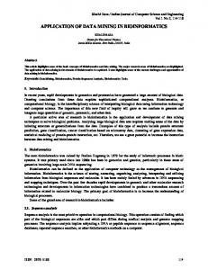
Figure 1. Construction of gabion-stepped weir with 2 plates and rods (above) and with mesh covering and stone filling (below).
Figure 2. Gabion stepped weirs with a slope of 1:2, without vertical impervious plate (left) and with vertical impervious plate (right).
98
F. SALMASI, M. T. SATTARI, M. PAL
2 q2 E0 = H + y + Va = H + y + 2g 2g (y + H) 2
Here, H is the total weir height measured with a point gauge after installation of the weir at the flume, y is the depth of flow measured about 60 cm upstream of the weir and above the weir crest, Va is the approach velocity, (Va = q/(y + H), q = Q/b), b is the weir width (i.e., 25 cm), q is the discharge per unit width of flume, g is gravity acceleration, Q is discharge, and E0 is the energy at the upstream of the weir. Energy at the downstream before the hydraulic jump is calculated by using the y2 depth, and energy at the toe of the weir is expressed by Eqs. (2) and (3). 2 q2 E1 = y1 + V1 = y1 + 2g 2gy 21
y1 =
y2 ( 2
1+8*(
yc 3 ) –1) y2
(4)
Here, ΔE is the difference between the energy at the upstream of the weir and the downstream of the weir before the hydraulic jump (ΔE = E0 – E1). Generally, energy dissipation depends on hydraulic and geometric variables. Using a Froude simulation, these variables can be expressed functionally as f(q, l , h , H , y, y 1 , y 2 , g, ρ, p) = 0, where p is the porosity of the stone-filled gabion, g is gravity acceleration, ρ is the specific mass of stone, h is each step height, l is each step length, and y is the depth of flow about 0.60 m upstream of the weir above the weir crest.
(2)
Using the Buckingham pi theorem, the dimensionless variables can be expressed as ΔE/E0 = f(q2/ gH3, h/l, p), where ΔE/E0 is relative energy dissipation and h/l is the weir slope.
(3)
Decision tree algorithm
Here, E1 is energy at the downstream of the weir before the hydraulic jump, V1 is velocity at the downstream of the weir before the hydraulic jump, y1 is the depth of flow before the hydraulic jump, y2 is the depth after the hydraulic jump, and yc is the critical depth, defined by yc = (q2/g)1/3. The locations of the measured y1 and y2 depths are shown in Figure 3. In all tests, discharge was regulated in such a way as to form the hydraulic jump at the weir toe so that supercritical flow at the downstream of the weir toe could occur (Froude number > 1). Although both y1 and y2 were measured, only the y2 depth was used in calculating energy dissipation, where relative energy dissipation rate is expressed by Eq. (4).
h
ΔE = E 0 –E 1 = 1– E 1 E0 E0 E0
(1)
Decision trees provide an effective way of implementing hierarchical classification. They are used in various applications due to their conceptual simplicity and computational efficiency. A decision tree classifier has a simple form that efficiently classifies new data and can be compactly stored. It can perform automatic feature selection and complexity reduction, while the tree structure gives information regarding the predictive or generalizing ability of the data (Pal and Mather 2003). In the process of constructing a decision tree, a data set is partitioned into purer, more homogenous subsets on the basis of a set of tests applied to one or more attribute values at each branch or node in the tree. This procedure involves 3 steps: splitting nodes, determining which nodes are
Air bubble not shown
Flow H
I Air bubble Y2 Y1
Figure 3. Location for measured y1 and y2 depths at the downstream of weir.
99
Application of data mining on evaluation of energy dissipation over low gabion-stepped weir
terminal nodes, and assigning class labels to terminal nodes (Quinlan 1993). The assignment of class labels to terminal nodes is based on a majority or weighted vote, where it is assumed that certain classes are more likely than others. A tree is composed of a root node (containing all of the data), a set of internal nodes (splits), and a set of terminal nodes (leaves). Each node in a decision tree has only 1 parent node and 2 or more descendent nodes. An observation vector is classified by moving down the tree and sequentially subdividing it according to the decision framework defined by the tree, until a leaf is reached (Brieman et al. 1984). In this paper, J48, a univariate decision tree algorithm (Witten and Frank 2005) that is a Java version of the popular C4.5 algorithm (Quinlan 1993), was used. The most important element of a decision tree algorithm is the method used to estimate the position of splits at each internal node of the tree. A number of algorithms have been developed to split the training data at each internal node of a decision tree into regions that contain examples from just 1 class. These algorithms either minimize the impurity of the training data or maximize the goodness. To do this, J48 uses a metric called the information gain ratio, which measures the reduction in entropy in the data produced by the split. Using this metric, the test at each node within a tree is selected using the subdivision of the data that maximize the reduction in entropy of the descendant nodes. The information gain and information gain ratio (Quinlan 1993) are developed as follows. For a given training set T, select one case at random and say that it belongs to some class Ci, having the probability shown in Eq. (5): f(Ci, T)/ |T|
(5)
m
info (T) = –/ f (C i, T) / T # i=l
log 2 (f (C i, T) / T ) bits. This quantity is known as the entropy of the set T. If a test Z partitions T into k outcomes, a similar measure can be defined that quantifies the total information content after applying Z, as shown in Eq. (6): infoz
Tj # info(Tj) T
k
(T) = / j=1
Using this approach, the information gained by splitting T using Z can be measured by the quantity in Eq. (7): gain (Z) = info (T) - infoz (T)
Thus, the information it conveys is: –log2(f(Ci, T)/|T|) bits. The amount of information required to identify the class for an observation in T can be quantified as: 100
(7)
This criterion is called the gain criterion (Quinlan 1993). We next select a test to maximize the information gain. This is also known as the mutual information between the test Z and the class. The major drawback of gain criteria is that they have a strong bias in favor of tests with many outcomes. The bias inherent in the gain criterion can be rectified by a kind of normalization in which the apparent gain with many outcomes is adjusted. If the information content of a message pertains to a case that indicates not the class to which the case belongs but the outcome of the test, then by analogy with the definition of info (T) (Quinlan 1993), the information generated by dividing Z into n subsets is given by Eq. (8): k
where f (Ci, T) stands for the number of cases in T that belongs to class Ci and |T| denotes the number of cases in T.
(6)
Split info (Z) =-/ j=1
Tj Tj # log 2 ( ) T T
(8)
This gives an idea of the potential information generated by dividing Z into n subsets, where the gain measures the information that arises from the same division that is useful for classification. Eq. (9) provides the proportion of information generated by the split that is useful for classification:
F. SALMASI, M. T. SATTARI, M. PAL
gain ratio (Z) = gain (Z)/split info (Z)
(9)
80 GH GV G GHV
70
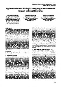
Decision tree classifiers divide the training data into subsets, which contain only a single class. The result of this procedure is often a very large and complex tree. In most cases, fitting a decision tree until all leaves contain data for a single class may overfit the noise in the training data, as the training samples may not be representative of the population they are intended to represent. If the training data contain errors, then overfitting the tree to the data in this manner can lead to poor performance for unseen cases. To address this problem, the original tree can be pruned to reduce classification errors when data outside of the training set are to be classified. To reduce the problem of overfitting, J48 uses an error-based pruning method that utilizes training data for this purpose. To estimate the accuracy of a predictive model performance, 10-fold cross-validation was used in the present study. The data were divided randomly into 10 parts, in which the class was represented in approximately the same proportion as in the full datasets. Each part was held out in turn and the learning scheme was trained on the remaining nine parts; its error rate was then calculated on the holdout set. Thus, the learning procedure was executed a total of 10 times on different training sets. Finally, 10 error estimates were averaged to yield an overall error estimate (Witten and Frank 2005). Results Experimental studies Figure 4 provides a comparison of the relative energy dissipation rate, ΔE/E0, with the values of flow rate per unit width (q) used in the present study. The symbols in Figure 4 are defined as follows: gabionstepped weir with horizontal impervious plate (GH), gabion-stepped weir with vertical impervious plate (GV), gabion-stepped weir without impervious plate (G), and gabion-stepped weir with horizontal and
60 50 ΔE / E0
Using this criterion, T is recursively split such that the gain ratio is utilized at each node of the tree. This procedure continues until each leaf node contains only observations from a single class, or until further splitting yields no gain in information.
40 30 20 10 0 0.00
0.02
0.04
0.06 0.08 q (m 2/s)
0.10
0.12
0.14
Figure 4. Relation between relative energy dissipation and discharge in unit width for 1:1 slope and 38% porosity; GH: gabion-stepped weir with horizontal impervious plate, GV: gabion-stepped weir with vertical impervious plate, G: gabion-stepped weir without impervious plate, and GHV: gabion-stepped weir with horizontal and vertical impervious plates.
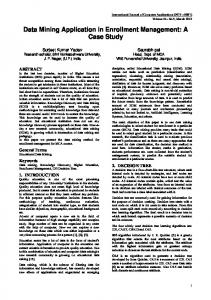
vertical impervious plates (GHV). Figure 4 shows that with increasing values of discharge per unit width, relative energy dissipation decreases for all weir arrangements. A reason for this is that with low flow rates, flow is in the nappe regime, and impinging jets on each step increase energy dissipation. This study suggests that a flow rate ranging from 5 to 40 L s–1 (representing 0.63-5.06 m3 s–1 m–1, full scale 1:10) works well with the gabion weir without causing any damage. In order to represent the relations between discharge and energy dissipation, a nondimensional dataset was used. Dimensionless parameters, q2/gH3 for discharge representation and 1/(1–K) for energy dissipation, where K = (E0–E1)/H, were used to plot a graph. Trend lines of energy dissipations for various discharges among different sets of data were obtained, and results were plotted in order to reduce the size of the manuscript. Figure 5 shows that at low discharge, more energy dissipation took place when a GHV weir was used. In comparison, for q2/gH3 > 0.005, energy dissipation is higher in G, GV, and GH weirs, and it was noted that the energy dissipation rates in these 3 weir types were very close to each other. This demonstrates that at low discharge with a nappe flow regime, flow 101
Application of data mining on evaluation of energy dissipation over low gabion-stepped weir
12 GHV 10
1/(1 - K)
8
GH
GV
G
GHV
6 4 2 0 0.0001
G GV GH 0.0010
0.0100 q 2/gH3
0.1000
1.0000
Figure 5. Relations between 1/(1–K) and q2/gH3 for 4 weir setups with slope of 1:1 and 38% porosity; GH: gabionstepped weir with horizontal impervious plate, GV: gabion-stepped weir with vertical impervious plate, G: gabion-stepped weir without impervious plate, and GHV: gabion-stepped weir with horizontal and vertical impervious plates.
occurs mostly through the weir body. This is a reason for lower energy dissipation in G, GV, and GH weirs compared to the GHV weir. This also suggests that, in the case of nappe flow over a GHV weir, step roughness has a significant effect, whereas in G, GV, and GH, most of the flow is through the weir body, and therefore flow resistance is lower. With an increase in discharge, flow occurs through both weir porous media and over the steps in G, GV, and GH weirs, causing more energy dissipation. On the other hand, energy dissipation decreases in the GHV type
of gabion weir. Furthermore, the G-type weir has more head loss in comparison to GV, GH, and GHV weirs when used with low discharges. This suggests that if weir design is based on nappe flow regime (based on step height and slope), the G-type will have more head loss. For a skimming flow regime, however, GHV will be better choice. Comparison of semipervious step faces (GH or GV type) revealed that a layer on the vertical face of each step (GV) has a greater effect on increasing energy dissipation than a horizontal layer (GH). This is due to the fact that when flow through a gabion medium hits the vertical face exerted on each step, more energy dissipation occurs than in a horizontal interaction. This is because flow net inclination results in flow impinging on vertical faces. At low discharge rates with a nappe flow regime, energy dissipation was found to be lower than in a GHV set-up only when through-flow occurred in G, GV, and GH setups. In a nappe flow in GHV, step roughness against the flow had a significant resistance effect, whereas in G, GV, or GH with only a through-flow, the flow resistance was lower. More energy loss was observed to occur with the smaller slope (1:2) than with the steeper slope (1:1). Table 2 provides the equations of dimensionless parameters obtained from Figure 5, in terms of power relations, along with their determination coefficients for the different types of weirs used in this study.
Table 2. Calculated fitness equations for physical models (slope of 1:1 and porosity of 38%). Weir type
Fitness equation
Determination coefficient (r2)
GHV
2 1 = 0.0804 ( q ) –0.6442 1–K gH 3
0.80
2 1 = 0.4195 ( q ) –0.3434 1–K gH 3
0.94
GV
2 1 = 0.613 ( q ) –0.2383 1–K gH 3
0.88
GH
2 1 = 0.6636 ( q ) –0.2061 1–K gH 3
0.74
G
102
F. SALMASI, M. T. SATTARI, M. PAL
Figure 6 provides a plot between q2/gH3 and 1/(1– K) with a 3-weir set-up. The results from the GHVtype weir (Figure 5) were not plotted so as to better distinguishing among the G, GV, and GH types. Figure 6 demonstrates that at high discharges with skimming flow regime, gabion-stepped weirs have more energy dissipation than impervious-stepped weirs, and comparison between semipervious faces showed that a layer on the vertical face of each step had more effect in increasing energy dissipation than the horizontal layer.
A total of 267 samples were used for all 4 types of weirs (G, GH, GV, and GHV). These data were obtained by varying the discharge (from 5 to 40 L s–1), weir slopes, and material porosity, and using impervious or pervious horizontal-vertical step surfaces. Figure 7 provides a model obtained by using a univariate decision tree classifier. A total of 5 attributes were used to classify the dataset into the required classes. The statistical properties and distribution of these attributes based on the physical tests are shown in Table 4. Visualization of results in Figure 7 suggests that the final tree has 23 leaves, and a total of 228 cases
5.0 4.5
1/(1 - K)
4.0
G
3.5 3.0
GH GV
GV
2.5
G
2.0 1.5 1.0 0.0001
GH 0.0010
0.0100 q 2/gH 3
0.1000
1.0000
Figure 6. Relations between 1/(1–K) and q2/gH3 for 3 weir setups with slope of 1:1 and 38% porosity; GH: gabionstepped weir with horizontal impervious plate, GV: gabion-stepped weir with vertical impervious plate, and G: gabion-stepped weir without impervious plate.
Decision tree method Because of the complexity that arises in Figures 4 and 5 for prediction of energy dissipation in gabion weirs, and in order to better understand the effects of different variables such as porosity and weir slope, the decision tree method was used to classify the weirs in term of energy dissipation. In this study, energy dissipation was classified into 4 categories (Table 3).
q2/gH3 0.0097: Very Low (120.0)
Figure 7. Decision tree classifier visualization.
Table 3. Classification of energy dissipation based on results obtained from physical models. Energy dissipation [(1/(1-K)]
7.3
Class
Very Low
Low
Medium
High
103
Application of data mining on evaluation of energy dissipation over low gabion-stepped weir
(85.4%) were correctly classified whereas 39 cases (14.6%) were classified incorrectly. An analysis of Figure 7 also suggests that if the parameter q2/gH3 is more than 0.0097, the energy dissipation is classified as Very Low and the tree growth stops. From a practical point of view, this is an undesirable rule. This rule is covered by 120 cases without any misclassifications. Thus, if the main purpose of the gabion-stepped weir is to maximize the energy dissipation, this condition will not be useful for design purposes. On the other hand, if q2/gH3 ≤ 0.0097, then Figure 7 provides 2 choices. The first is q2/gH3 ≤ 0.0021 and the second is q2/gH3 > 0.0021. Classes with High or Medium energy dissipations are the desired states for a designer. For practical purposes, the best rule would be that if q /gH3 is less than or equal to 0.0021, both horizontal and vertical impervious layers exist, and the slope 2
is 1:1, then energy dissipation would be High. This rule covers 9 cases without any misclassifications, suggesting that this rule should be applied in the design of stepped gabion weirs. To show the interclass distributions and possible false classifications, a confusion matrix was generated (Table 5). This suggests that in the High energy dissipation class, the classification process was accurate for all cases, but for the other 3 classes, cases beyond the diagonal line (shown in grey in Table 5) had some deviations. The following cases were incorrectly classified: in the Medium class, 5 cases (3 + 2); in the Low class, 18 (13 + 5); and in the Very Low class, 16 cases (15 + 1). From a practical point of view, for a hydraulic engineer, the High class is a desirable case and the Very Low class is an undesirable case.
Table 4. Properties of selected attributes based on physical tests. Slope
Porosity (%)
GH
GV
(1/(1-K)
No. Label
Count
Label
Count
Label
Count
Label
Count
Label
Count
1
1:1
152
38
87
Yes
128
Yes
121
Very Low
199
2
1:2
115
40
90
No
139
No
146
Low
51
42
90
Medium
8
High
9
3 4
Table 5. Confusion matrix of decision tree model.
104
Very Low
Low
Medium
High
classified as
183
13
3
0
Very Low
15
33
2
0
Low
1
5
3
0
Medium
0
0
0
9
High
F. SALMASI, M. T. SATTARI, M. PAL
Discussion Experimental investigation was conducted on 8 physical models of gabion-stepped weirs. Results show the usefulness of this type of structure because of the positive effect of its porosity. A comparison between the present study and that of Peyras et al. (1992) is provided in Figure 8 for a spillway with a slope of 1:1. Good agreement exists between the experiments carried out in present study, especially for stone with a size of 25-38 mm, and the results of Peyras et al. (1992). Peyras et al. (1992) used dimensionless parameter (E0 – E1)/H in their study, and the comparison in Figure 8 is based on this parameter. Based on Figure 8, stone size has a slight influence on energy loss. The study by Peyras et al. (1992) also suggests that gabion-stepped weirs could withstand a unit discharge (q) of up to 3 m3 s–1 m–1 without significant damage. Based on the present study, gabion weirs are able to withstand a unit discharge (q) of up to 5 m3 s–1 m–1 without any damage. Based on these experiments, the porosity values selected (38%, 40%, and 42%) do not have an essential effect on energy loss. This suggests the need
for more tests with different porosity values. Slopes of 1:1 and 1:2 had no effect on energy dissipation in the present study. This may be due to the low height of the weirs (i.e., 30 cm). In addition, Figure 8 shows that application of the decision tree method can be useful for solving hydraulic engineering problems, such as the one presented in this paper, in order to understand complex relationships among several parameters affecting energy dissipation in stepped gabion weirs. From Table 5, it can be seen that the decision tree classifier correctly classified 183 cases in the Very Low category, 33 cases in Low, 3 cases in Medium, and 9 cases in High. On the other hand, 15 Very Low class cases were wrongly classified as Low, and 1 case was wrongly classified as Medium. In the Low class, 13 cases were wrongly classified as Very Low and 5 cases were wrongly classified as Medium. In the Medium class, 3 cases were wrongly classified as Very Low and 2 cases were wrongly classified as Low. However, in the High class, there were no wrongly classified cases. As shown in Figure 9, decision tree algorithms can be used to predict the energy dissipation class with reasonable accuracy.
220
0.9
200
0.8
180
0.7
160 Number of cases
(Eo-E 1)/H
1
0.6 0.5 0.4 0.3 0.2 0.1 0 0.0001
Peyras et al (1992) Present study (16-19 mm) Present study (19-25 mm) Present study (25-38 mm) 0.001
q 2/(gH 3)
199 183 Physical test
140
Decision tree
120 100 80 51
60
33
40
8
20
3
9
9
0 0.01
0.1
Figure 8. Comparison between present study and that of Peyras et al. (1992).
Very Low
Low Medium Energy dissipation class
High
Figure 9. Comparison of number of classes derived from physical tests and decision tree.
105
Application of data mining on evaluation of energy dissipation over low gabion-stepped weir
Symbols b: weir width equal to 25 cm E1: energy at the downstream of spillway before hydraulic jump Eo: total energy at the upstream of weir ΔE: difference between energy at the upstream and downstream of weir (ΔE = E0 – E1) Fr: supercritical Froude number = V1 / gy 1 g: acceleration due to gravity h: each step height H: total weir height from flume bed l: each step length p: stone porosity filled in gabion K: relative energy dissipation defined as: K = (E0 – E1)/H q: flow rate or discharge per unit width Q: total discharge h/l: weir slope (V:H) Va: approach velocity Va = q/(H + y) V1: velocity at toe of weir y: depth of flow about 60 cm upstream of weir, above weir crest y1: depth before hydraulic jump at weir toe y2: depth after hydraulic jump References Breiman L, Friedman JH, Olshen RA, and Stone CJ (1984) Classification and Regression Trees. Wadsworth Belmont, California, USA.
Pal M, Mather PM (2003) An assessment of the effectiveness of decision tree methods for land cover classification. Remote Sens Environ 86: 554-565.
Chanson H (2001) The Hydraulics of Stepped Chutes and Spillways. A.A. Balkema Publishers, Lisse, the Netherlands.
Pal M, Mather PM (2004) Assessment of the effectiveness of support vector machines for hyperspectral data. Future Gener Comput Sys 20: 1215-1225.
Chanson H (2006) Hydraulics of skimming flows on stepped chutes: the effects of inflow conditions. J Hydraul Res 44: 51-60. Chinnarasri C, Donjadee S, Israngkura U (2008) Hydraulic characteristics of gabion-stepped weirs. J Hydraul Eng ASCE 134: 1147-1152. Foody GM, Mathur A (2004) A relative evaluation of multiclass image classification by support vector machines. IEEE Transactions on Geoscience and Remote Sensing 42: 1335-1343. Gonzalez CA, Takahashi M, Chanson H (2008) An experimental study of effects of step roughness in skimming flows on stepped chutes. J Hydraul Res 46: 24-35. Kells JA (1993) Discussion of spatially varied flow over rockfill embankments. Can J Civ Eng 20: 820-827. Matos J, Quintela A (1994) Discussion of jet flow on stepped weirs. J Hydraul Eng ASCE 120: 443-444.
106
Peyras L, Royet P, Degoutte G (1992) Flow and energy dissipation over stepped gabion weirs. J Hydraul Eng ASCE 118: 707-717. Quinlan JR (1993) C4.5 Programs for Machine Learning. Morgan Kaufmann, California, USA. Rajaratnam N (1990) Skimming flow in stepped weir. J Hydraul Eng ASCE 116: 587-591. Stephenson D (1979) Gabion energy dissipaters. 13th International Congress on Large Dams, New Delhi, India, Q. 50, R. 3, pp. 33-43. Toombes L, Chanson H (2008) Flow patterns in nappe flow regime down low gradient stepped chutes. J Hydraul Res 46: 4-14. Witten IH, Frank E (2005) Data Mining, Practical Machine Learning Tools and Techniques, 2nd ed. Morgan Kaufmann, California, USA.