Rainey, Thomas and Pennisi, Steve and Joyce, James (2004) Applying
Computational Fluid. Dynamics Modelling to Optimise Environmental
Performance at ...
COVER SHEET Rainey, Thomas and Pennisi, Steve and Joyce, James (2004) Applying Computational Fluid Dynamics Modelling to Optimise Environmental Performance at Minimum Cost. In Proceedings 58th Appita Annual Conference and Exhibition Incorporating the Pan Pacific Conference, pages pp. 239-243, Australia, Australian Capital Territory, Canberra.
Accessed from http://eprints.qut.edu.au
Copyright 2004 the authors.
Applying Computational Fluid Dynamics modelling to optimise environmental performance at minimum cost T. RAINEY, S. PENNISI AND J. JOYCE Sugar Research Institute SUMMARY This paper describes recent advances in process design, made through the application of Computational Fluid Dynamics (CFD) modelling in the sugar industry and proposes that similar advances are possible in pulp and paper. CFD models have proven to be very useful when used as an engineering design tool and as a research and development tool. A significant advantage of computer-based simulation over pilot testing is the reduction in the time and capital cost required to investigate design changes. However, the biggest advantage of computer simulations is that they allow the user to visualise the process in ways not otherwise possible, and do this without the high cost and risk to product quality or safety that exists with conventional experimental methods. This allows the traditional processes of technology development, through pilot plant testing and incremental changes at full scale, to be short cut or even bypassed completely. Real world applications of CFD modelling in the sugar industry are described in this paper. These include the reduction of CO, NOx, SOx and particle emissions from furnaces and optimising the design of several process plant items to maximise throughput and performance. CFD is now routinely used by the Sugar Research Institute to examine, improve and refine process equipment in sugar factories. All of these applications have very similar parallel applications within the pulp and paper industry. THE OPERATION OF CFD Computational Fluid Dynamics (CFD) models are a series of mathematical equations that describe the motion of fluids, heat transfer and chemical reactions and the resultant interactions with physical geometries. There is also scope to model multiphase flow. The equations are coupled and solved simultaneously in an iterative process to arrive at a final solution. While the Navier Stokes and continuity equations are the predominant descriptors of the fluid motion, other equations can be linked until an adequate description of the physical process is produced. The number and form of the equations used are different for each case, since every flow problem has different parameters of importance. CFD techniques are developed in the most general way possible so that they can be applied to almost any application, so long as the governing fluid behaviour can be described mathematically. Industrial applications of CFD vary from the design of aircraft through to nuclear powered boilers, heart valves, pumps, turbines, mixers, burners and fluidised beds. CFD models allow the user to visualise the operation of equipment in ways that cannot be matched by real world measurements. CFD models can drastically reduce the cost of implementing design improvements, because large changes to geometry or processing conditions can be applied to the model without interruption to plant operation or requiring vessel modifications of any sort. The models can also be used to simulate operation well outside of the “normal” operating parameters, where product quality or safety could be compromised. This makes CFD useful as a research, troubleshooting and development tool. As with other simulation techniques CFD requires validation to ensure the quality and realism of the model predictions. The type and amount of comparison data required is different in each case and, like the equations used, is dependent upon what parts of the physical process are most important. CFD modelling can dramatically reduce the time from concept development to implementation, by minimising the physical testing required to develop and prove new designs or design improvements. Experience in the sugar industry has shown that CFD modelling has the ability to improve on long standing, empirically optimised designs. For example, a high capacity juice clarifier was designed by SRI in 1969 and was extensively adopted throughout the world's sugar industry as the best technology for the application. This model of clarifier performed well and was derived through empirically optimised design and iterative pilot scale testing. The initial work design took nearly a decade to complete and incremental improvements were being made for 25 years. In the 1990’s, a preliminary
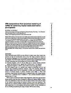
investigation into clarifier design was performed using CFD and the analysis demonstrated that SRI's design had significant room for improvement in flow profiles. Development of the new generation clarifier was initiated in 1996 and proven at full scale around 12 months later, without any pilot scale testing. The resulting design was an immediate success and resulted in a capacity increase of as much as 75% over the original design (Dixon et al.,2003). A similar use of CFD, to address measured short circuiting in a plug flow cooling crystalliser, resulted in the installation of baffles, which were subsqeuntly shown to substantially improve the plug flow characteristic. The resulting increase in sugar recovery was estimated to yield a 7 week financial payback for the installation. FURNACE MODELLING Sugar mills use boilers to produce high-pressure steam for shaft power production in steam turbines, with the exhaust then being used as process steam. These boilers are fired using the fibrous waste (bagasse) from the sugar cane plant. Some mills also use coal as a supplementary fuel for certain circumstances. SRI uses an in-house developed CFD code called FURNACE for most of the work on bagasse and co-fired boilers. Reduction of CO, NOX and SOX Boiler performance and furnace emissions such as CO, NOx, SOx, unburnt fuel and particulates are of considerable concern to the sugar industry. The production of CO inside the furnace cannot be predicted accurately in absolute terms because the mechanisms of CO formation are so complex. However, CFD models are capable of predicting relative changes in CO production inside the furnace as a result of design changes (see figure 1). This is useful for implementing design changes with the knowledge that CO production will be decreased, but the absolute magnitude of the improvement cannot be known until real measurements can be taken from the vessel. SRI has used CFD to investigate the effect of various secondary air injection configurations on final CO concentration, on a commercial consulting basis. Similar work has been done for NOx and SOX control. All industries using a combustion furnace can benefit from the application of these CFD modelling tools.
Figure 1 CO distribution through a furnace (light colours represent high concentration) Reduction of flue gas particulates Wet flue gas scrubbers are used in the Australian sugar industry to remove fine soot and char from boiler flue gases. Boiler gases are introduced tangentially into the bottom section of a cylindrical vessel. The flue gas passes through several water curtains which capture the particulates. A common problem in wet scrubbers is the formation of ash deposits on the inlet to the vessel, resulting in higher gas flows and darkening the exhaust flow with carried over particulates. The result is ash build up on
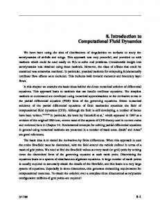
the induced draft fan impeller, leading to imbalance problems. Furthermore “black rain” due to carryover of water into the exhaust stream can occur. When the CFD analysis was undertaken on a common industrial scrubber, it was found that there was significant recirculation of the flue gas back down the scrubber that lead to the settling of ash in the inlet pipe (see figure 2). By adding a baffle plate inside the scrubber, CFD analysis showed that these recirculation patterns could be eliminated thereby reducing problems with ID fan instability and black rain (see figure 3). As of 2004 the proposed alterations had not been attempted in a commercial installation.
Figure 2- CFD prediction of the flow field within the unmodified wet flue gas scrubber and consequent recirculation
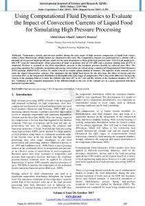
Figure 3- CFD velocity profile with addition of a baffle to stop recirculation Tube erosion CFD modelling has also been used on roughly a dozen boilers to date, to successfully minimise tube erosion. Many sugar mills have had to replace complete convection banks at considerable expense. Plaza et al., (1999) investigated three problematic sugar industry boilers, the Kalamia CRD boiler, Mulgrave JTA boiler and Mourilyan CRD boiler, all of which required major convection bank tube replacement or repairs during the 1996 and 1997 maintenance seasons. These boilers were modelled using CFD and zones with high particulate content and with a velocity angled towards the boiler walls were identified, as shown in figure 4. Recommendations included increasing the height of the rear wall and removing the original baffles. Table 1 shows the tube wear rates before and after the recommendations were implemented. The result was that the tube banks in the new design now last around twice as long as the original. For Mulgrave mill, for example the convection bank will last 16 years instead of eight resulting in savings of $1.5 million every 8 years.
Erosion
Figure 4 Velocity contour vector plot used to examine the cause of erosion in a bagasse fired furnace Table 1 Summary of tube wear rates in boilers before and after recommendations from CFD modelling were implemented (Plaza et al.) Boiler Kalamia Mulgrave Mouralyan
Wall loss prior to modifications (mm per season) 0.1 (on most tubes) 0.1 to 1.0 0.2 to 0.7
Wall loss after modifications (mm per season) 0.1 to 0.15 (localised) 0.2 to 0.4 (localised) 0.1 to 0.2 (estimated)
CLARIFIER MODELLING Clarifier vessels are used in the sugar industry to remove particulates from the raw juice that has been squeezed out of the cane. A clarifier works on the principle of slowing the liquid phase and allowing the solid phase to settle out under gravity. Flocculants are added to the feed stream to speed up the settling process. The clear liquid leaves from the top of the vessel and the solids are removed from the bottom (see figure 5). The basic operating principles are the same as thickener vessels used in minerals processing industries. The fundamental difference between thickeners and clarifiers is which stream is of interest for further processing. In the case of the sugar industry the clear liquid (containing sucrose) is used for further processing and the solids removed from the bottom of the vessel are considered a waste product. The analogue in the pulp and paper industry are the clarifiers for primary treatment of effluent from pulp and paper mills.
Juice overflow weir at outlet Scrapers to move solids Solids outlet Figure 5 Standard SRI clarifier used in the sugar industry Clarifiers rely on holding the liquid for a period of time to allow the solids to settle out. Capacity can be increased and/or performance can be improved by simply making the vessel larger. However, this has capital cost implications, and in the case of sugar cane juice processing, product degradation occurs over time. So it is of considerable benefit if the residence time of the vessels can be reduced.
Through the use of CFD modelling of clarifier vessels, understanding of the flow behaviour inside clarifier vessels was dramatically improved. From these analyses an improved design of clarifier vessel has been developed as illustrated in figure 6. This new design is now viewed as the benchmark technology for sugar juice clarification throughout the world. CFD modelling allowed the time from the project concept to full scale validation to be less than 12 months.
Figure 6
Predicted velocity field in a standard sugar industry clarifier and in a New Generation Clarifier (vessel split at line of symmetry, the colour range represents the fluid velocity range).
EFFLUENT POND MODELLING Effluent treatment in ponds are the last processing step before release into the surrounding waterways and so has particular relevance to the environment. The rules of thumb used for the design of effluent ponds tend to be very rudimentary and are generally not based on an understanding of the physical process. Although the flows are slow moving they are very three-dimensional when considering the effects of heating from the sun, wind effects on the top surface of the fluid, eddy current production by agitators and changes in flow rate through the system. CFD techniques allow for all of these effects to be modelled simultaneously and dynamically (ie. over time). The prediction can also be interrogated to calculate the Residence Time Distribution (RTD), useful for the case where the reaction occurring inside the pond is time dependant. RTD information is also useful in determining the amount of mixing and short-circuiting that occurs inside the pond. SUMMARY OF THE APPLICATIONS IN THE SUGAR INDUSTRY Applications of CFD modelling in the sugar industry are too broad to cover in their entirety. However, a short list of applications is included in table 2.
Table 2 Applications of CFD in the sugar industry including parallels in the pulp and paper industry Application Troubleshooting: Reducing tube erosion in boilers Optimising boiler convection bank heat transfer Optimisation of secondary air for flame manipulation and CO minimisation Cooling crystalliser residence time optimisation Stirred vacuum pan design optimisation
Comments Same potential application in the pulp and paper industry
Clarifier design optimisation
Similar to those used in the chemical recovery plant of a pulp mill Same potential application in the pulp and paper industry
Effluent pond design and optimisation Optimisation of design in heat recovery steam generators Flotation clarifiers Gasifier design
Same potential application in the pulp and paper industry Same potential application in the pulp and paper industry Example of a multi-phase, high viscosity material in stirred tank with cooling heat transfer. Example of a multi-phase, high viscosity material in stirred tank with boiling heat transfer.
Same potential application in the pulp and paper industry Example of a process where high viscosity fluids are being handled. Example of a process involving simultaneous mass transfer, heat transfer and chemical reaction, between a solid and a fluid. Can also be applied to black liquor evaporation or gasification.
OTHER APPLICATIONS Evaporators SRI has had considerable success in modelling evaporators. In the sugar industry, the juice must be concentrated from around 15% dry solids to 68% dry solids, which has a close parallel to evaporation of black liquors. A recent study showed that the current inlet pipe configuration of many exisiting units did not evenly distribute the juice into the calandria, resulting in a series of dead zones and high velocity zones, causing short circuiting and recirculation within the calandria. This was found to reduce heat transfer performance. Altering the feed inlet distributor, through CFD optimisation has had a significant impact on the performance of these vessels, with increases in heat transfer performance of up to 10% in full scale units. Potential applications in the pulp and paper industry CFD can be utilised to optimise processing equipment commonly used in the pulp and paper industry. Apart from applications such as the design of furnaces, clarifiers evaporators and effluent ponds, other possible applications include the design of digesters, headboxes and fan pumps. Temperature and velocity distributions exist within digesters affecting their ability to homogeneously cook the fibre. A CFD model could be used to identify problem areas with stagnant zones in current designs and circulation patterns. The geometry of both the digester and feed lines can be easily manipulated to provide better conditions to produce pulp with a more consistent kappa number. CFD could be applied to improve existing or design new headboxes. Flow patterns inside the headox could be determined and solutions for problems such as CD basis weight variability could be determined. CFD analysis could make recommendations for headbox retrofits. Using physical models, designing a headbox can be quite a time-consuming and costly exercise. However, CFD design is much more cost-effective and less time consuming process to achieve the same results.
Using a series of runs on a CFD model, fluctuations in pressure generated from fan pumps can be identified. The effects of subtle variations to the impeller design can be determined to try and improve fan pump design to minimise pulsations in flow and improve MD basis weight variability. More efficient pumps can be designed using CFD, reducing energy consumption. CONCLUSIONS CFD modelling has had a considerable impact in various applications within the sugar industry. Many of these applications have parallels with the pulp and paper industry. Applications such as clarifiers, effluent treatment ponds and furnace emissions have direct relevance to environmental impact and experiences in the sugar industry have demonstrated that significant improvements can be made through the application of CFD modelling techniques. Evaporators, digesters, headboxes and fan pumps are likely candidates for improvements in the pulp and paper industry through the use of CFD modelling techniques. While it must be recognised that some research and development will be required, the nature of the applications identified here are considered to be reasonably straightforward applications for existing capabilities. This being the case then almost immediate benefits from CFD are possible. ACKNOWLEDGEMENTS CO and furnace velocity plots used with the kind permission of Thermal Energy Systems cc. Wet scrubber velocity plots used with the kind permission of the project syndicate members (Mulgrave Central Mill, Isis Mill, MSCA, BSL and Broadwater Mill). Information on the evaporator modelling was used with the kind permission of The Andra Sugars Ltd and the authors S.N. Pennisi and S.Y. Tan REFERENCES Dixon, T., Mann, A., Hobson, P., Plaza F., Pennisi, S., and Steindl, R. Applications of CFD in the Sugar Industry, Third International Conference on CFD in the Minerals and Process industries, CSIRO, (2003) Plaza, F., Dixon, T.F., Dickenson, N.L., Fitzmaurice, A.L. and Owens, M., Performance of baffled boilers with redesigned convection banks, Proc. Aust. Soc. Sugar Cane Technol., 21:432-437 (1999)