2003-01-0856
Architecture Centric Modeling of Automotive Control Software Dr. Ulrich Freund
ETAS GmbH – Research & Development
Dr. Michael von der Beeck
BMW Group – Function Development Process
Peter Braun, Martin Rappl
Munich University of Technology – Department of Computer Science Copyright © 2003 Society of Automotive Engineers, Inc.
ABSTRACT Within the automotive industry model-based specification techniques are the basis for the definition of seamless design processes allowing the complete, the consistent, and the unambiguous specification of software and hardware parts of car specific networks of control units. For a successful application, those modeling approaches have to give methodical support for adequately capturing the architecture in the targeted system class. In our opinion most standard modeling languages leave room for improvement exactly at this point. Therefore we develop a modeling language characterized by the following features: (1) architecture centric modeling, (2) domain-specificity, and (3) close relation to standard modeling languages. Within this article we introduce the Automotive Modeling Language (AML) by illustrating a case study which comprises parts of the body car electronics within a car. Architecture related modeling concepts are discussed in detail by showing the correlation between their UML representation and their ASCET-SD representation.
INTRODUCTION The development of software for electronic control unit (ECU) networks in the automotive domain has been influenced by a major structural change in the last few years. Abstract model-based specification techniques are becoming more and more important while traditional programming languages gradually lose importance. This change is primarily being facilitated by a growing understanding of what application requirements are, which has resulted in new modeling constructs and languages. The architecture of automotive embedded systems and their model-based representation plays an outstanding role in this field. By means of an appropriate architecture the management of the huge amount of signals within a car, the understanding of interaction
relations within the functional network and the flexible deployment of functions can all be guaranteed. This technical paper introduces the modeling language AML (Automotive Modeling Language), an architecture centric language for analyzing and synthesizing automotive embedded systems. Similar to other Architecture Description Languages (ADLs) it offers commonly accepted modeling constructs for specifying the software and hardware part of the systems architecture. The architecture is described by using components, in- and outports, and connectors. The abstract syntax of the AML provides a conceptual and methodological framework as a prerequisite for a welldefined semantics of the offered modeling constructs. The usage of different kinds of textual, graphical, or tabular notations for a concrete model representation is supported. AML models can be represented by various notational elements offered by wide spread modeling languages and tools such as ASCET-SD, UML (1.4/2.0) [22,28] and UML-RT. AML differs from other languages by some further capabilities. First, the AML defines a terminology specifically adapted to the application domain of embedded systems in the automotive area. Second, the AML includes a system of abstraction levels allowing systems to be specified on different technical levels. Last but not least, the AML incorporates concepts for the formation of variants to support a product line development approach. STRUCTURE OF THE PAPER – The paper outlines central terms introduced by the AML and used in the context of automotive embedded real-time software development. Thereupon the concepts for a seamless and integrated development methodology with the focus on logical functions, on variants and on the functional network are illustrated. •
In the first two sections ADL related modeling concepts and extended features of the AML are described in the manner of a glossary for further reference.
•
In the subsequent section each ADL modeling concept is introduced and is illustrated by means of a consistent case example showing a small portion of functions included in BMWs body car electronics. Together with the ASCET-SD representation the corresponding more abstract UML representation is presented. The used subset of notations conforms to the AML related modeling style, which is necessary for the exchange of models between the UML Suite, DOORS, and ASCET-SD.
•
Thereupon rests the description of the tailoring process of functions to particular functional variants and the instantiation process to functional instances which build up the functional network.
•
In the final section we draw our conclusions and provide an outlook to future work.
agreement in the research community on the meaning of “architecture description language” (ADL). To put an end to this situation, Medvidovic and Taylor started from the definition of “software architecture”, as given by Shaw and Garlan [13]: “Software architecture involves the description of elements from which systems are built, interactions among those elements, patterns that guide their composition, and constraints on these patterns.” After a comprehensive evaluation of previous ADL surveys, an evaluation of specific software architecture workshops and after individual ADL studies Medvidovic and Taylor ended up with an ADL classification framework. According to this framework an ADL must explicitly model components (incl. ports), connectors, and their configurations. These mandatory ADL modeling concepts are described as follows: •
A component in an architecture is a unit of computation or a data store. It must provide an interface which specifies the services (messages, operations, and variables) the component provides. This interface can also specify needed services. Interfaces are described by ports.
•
A connector is an architectural building block used to model interactions among components and rules that govern those interactions.
•
(Architectural) configurations are connected graphs of components and connectors that describe architectural structure.
Along with the presentation of architectural modeling concepts additional modeling concepts for (inter-)action, for dynamic behavior, and for modeling real-time constraints are introduced. These concepts are needed to visualize complete and realizable models within the tool ASCET-SD. THE PROJECT AUTOMOTIVE – The work presented stems from the research project AUTOMOTIVE Requirements Engineering of Embedded Systems, which 1 is part of FORSOFT II . In the project AUTOMOTIVE the Technical University of Munich, the tool vendors ETAS and Telelogic, the car manufacturers BMW and Opel as well as the component suppliers Bosch and ZF are closely working together on specific aspects of the methodology, to adapt the UML and ASCET-SD notations in the context of automotive systems development, and to implement a closely linked tool chain including the tools ETAS ASCET-SD, Telelogic UML Suite, and Telelogic Doors. In addition, BMW, Opel as well as Bosch and ZF are validating the concepts being developed.
THE ROLE OF ARCHITECTURAL DESCRIPTION As the software systems within the automotive area are getting more and more complex it is very important to structure them in an appropriate manner. Architecture description languages provide some help for these structuring processes. In the following mandatory concepts of architecture description languages are introduced. Also some related work within the automotive area is mentioned. ARCHITECTURE DESCRIPTION LANGUAGES At least until the classification and comparison work of Medvidovic and Taylor [21] there was a lack of 1
This work was partially founded by the Bayerische Forschungsstiftung (BayFor) within the Forschungsverbund für Software Engineering II (FORSOFT II).
Note that these elements are purely concepts. They also need at least one concrete representation. For example a component could be graphically represented by a rectangle or by a circle. UML AS AN ADL? It is interesting to explore whether the UML constitutes an ADL. There are several statements about the current UML Version 1.4 concerning this question. Medvidovic et al. state [19]: “One conclusion of our work is that UML currently lacks support for capturing and working with certain architectural concerns whose importance has been demonstrated through the research and practice of software architectures. In particular, UML lacks direct support for modeling and making practical use of architectural styles, explicit software connectors, and local and global architectural constraints.” Furthermore, Medvidovic and Taylor concluded [21]: “The focus on conceptual architecture and explicit treatment of connectors as first-class entities differentiate ADLs from ... OO notations and languages (e.g., Unified Modeling Language).”
AUTOMOTIVE-SPECIFIC ADAPTATIONS There has been a lot of activity to tailor or develop architecture description languages to meet automotive needs. For example, in 1994 the TITUS-project [7] was started by DaimlerChrysler. Titus is an interface based approach [9] which resembles the ROOM [24, 26] methodology, but differs considerably in details mainly to make an ‘actor-oriented’ approach suitable for ECUSoftware. A detailed comparison between the TITUSand the ROOM methodologies is given in [18]. Projects focusing on similar aspects are the BROOM methodology of BMW [12], and the French AEE research effort [3]. The latter project expresses ADL concepts by means of standard UML and uses the tool ASCET-SD [1] to bring designs down to ECU software. Last but not least, in 2 spring 2001 the European research project EAST/EEA was started as an ITEA project. One of the main goals of the EAST/EEA project is to develop a standardized ADL for automotive software compliant with the UML 2.0 [28], the major new version of UML that is currently being developed by the OMG. OUR PROPOSAL: AML The above-mentioned projects clearly indicate the importance of automotive-specific concepts for architecture description languages. Instead of finding commonly accepted abstractions we try to establish a terminology in the domain of embedded automotive realtime software. For that we introduce the AML as an automotive-specific modeling language.
SURVEY OF AML MODELING CONCEPTS In our opinion an automotive-specific modeling language should include the previously introduced modeling concepts of general purpose ADLs. We also require the following aspects of a modeling language in the automotive area: •
Automotive-specific terminology
•
System of abstraction levels
•
Elements, variants, and instances
•
Metamodel
•
Tool support
These aspects are explained in more detail in the following sections. AUTOMOTIVE-SPECIFIC TERMINOLOGY A major part of an architectural language is to provide a terminology (also ontology) for talking about architectural issues. The AML introduces a terminology which is well suited for embedded automotive real-time software. It 2
Embedded Architecture Software Technology/Embedded Electronic Architecture
includes notions well known in the automotive domain such as signals, functions, electronic control units, realtime operating systems, communication infrastructure, and processors for assembling the automotive embedded systems architecture. Each of these notions constitutes a fragment of the architectural model at a distinct level of abstraction. Table 1 shows AML relevant notions and their classification within abstraction levels. For each class of architectural information the corresponding behavioral modeling concept is given. The cohesion between the static and dynamic modeling concepts is realized by actions. Actions and their causal and their temporal ordering can be considered as an invariant information accessible at every abstraction level. AML Abstraction Levels Signals Functions Logical Architecture
ArchitectureCentric • Signals • Functions • Functional Cluster
• Control Units • Central Processing Units Technical • Communication Architecture Infrastructure • Real-Time Operating Systems Implementation
Dynamic • Algebraic Expressions • Difference Equations • Statemachines • Difference Equations • Statemachines • Difference Equations • Statemachines • TechnicalOriented Models
Table 1: AML-Specific Terminology In the sequel we list all architecture centric notions of this terminology (cf. Table 1) with respect to their classification within the system of AML specific abstraction levels. We informally describe their semantics and their use as modeling concepts. In addition the AML offers general applicable modeling concepts such as hierarchical structuring, instantiation, formation of variants, formation of configurations, and model composition for each notion presented. SYSTEM OF ABSTRACTION LEVELS Abstraction levels define restrictive views on the system model to structure and filter information. Each level rests upon more abstract levels. So in a more technical level access to the information contained in a more abstract level is permitted. At each abstraction level semantic properties are considered which are characteristic for the corresponding technical level. In the development process, the transition from an abstract level to a more technical level means to restrict the design space.
Signals. The abstraction level signals contains model information about the system with the least amount of technical details. The core modeling concepts at this stage are signals and algebraic expressions. Signals are elementary entities, which can be exchanged between actors, sensors, and control units. Each signal can be measured or computed from a physical context. Separate management of all signals occurring in a car is essential to construct architectural models since their number goes far beyond ten thousand. Algebraic expressions allow signals to be modified with respect to a set of elementary operations. Actions denote different kinds of operations. Together with a causal and a temporal ordering mechanism actions provide enough modeling power to describe scenarios. Scenarios are ordered sequences of actions to achieve a determined goal in the context of the systems operation. Functions constitute basic building blocks at a high level of abstraction independent of concrete implementation techniques or target languages. Those functions which behave as abstractions of control units, actors, sensors, or the environment are given special consideration during modeling. Each function is provided with an interface stating the required and the provided signals. Those interfaces are used to model in- and outports of functions. For reusability reasons functions prohibit the access to local signals by scoping them. On this account communication has to be handled explicitly via signal passing between ports. Explicit representation of signal dependencies between different control functions is an essential ingredient of architectural models. Since functions respectively their instances are entities which can be deployed to different control units, the consistent and the complete capture of model information in terms of signal dependencies between functions supports the analysis of functional networks and furthers the collaboration of distributed development teams. Logical Architecture. The logical system architecture is determined by the specification of functional clusters where fragments of the functional network are deployed. These functional clusters characterize potential control units, actors, sensors and the environment. At this stage dealing with the entire system as a whole changes into dealing with a set of independent subsystems working interactively together. Experiences from the development of electronic control units reveal that a clear separation between the logical system architecture level and the technical system architecture level is very helpful when partitioning functions on ECUs. At the logical architecture level only a subset of partitioning criteria is applied in order to achieve a clear view of the functional structure - without identifying the set of functions, which constitutes an ECU. However, finally the complete set of partitioning criteria (e.g. also those which consider geometric requirements) has to be applied.
Technical Architecture. The technical architecture level is determined by two factors: (1) Finalizing the responsibility of each control unit by applying the full set of partitioning criteria in terms of technical, economical, quality, and political constraints. (2) Connecting functions and functional clusters model-based with the technical infrastructure (processors, real-time operating systems, and communication infrastructure). Implementation. At the implementation level the model is realized in hardware and software. This level has an exceptional place in the system of abstraction levels since no further information is added to the model. Code generation and the installation of hardware go far beyond the realization of first prototypes that could be generated from the models created above. However there are many examples of how to successfully apply simulation and code generation facilities in the areas of testing and rapid prototyping. Nevertheless code generation often fails to fulfil domain-specific limitations. For this reason the size and the execution time of the generated code has to be optimized manually at the implementation level. ELEMENTS, VARIANTS, AND INSTANCES In addition to the intrinsic, architecture-centred modeling concepts, the AML incorporates generally applicable modeling concepts for specifying elements, variants and their instances. Elements are basic entities which can be used and referred to within the overall specification. Elements are classified within the terminology and they have relationships (dependencies) among each other. Elements and their dependencies manifest a so called model framework which is the initial point for further development activities at each abstraction level. The great number of elements within ontologies can be hierarchically structured to organize the information and to locate each element easily. The formation of variants allows elements to be applied to a specific use according to the current context. From a methodological point of view the relation between elements and their variants allows complexity to be managed by abstracting specialized details to general information needed for the model. In contrast to the concept of inheritance in object orientation building variants from model elements just means to select specific subelements from all available elements. The subelement relationship between elements is defined by the hierarchical structure of elements. A variant of an element differs from the element mainly by defining a subset of the elements´ subelements. To transform elements and variants in a running system instances have to be derived. Analyzing instantiated elements and their dependencies is essential for defining correct systems at each abstraction level.
METAMODEL
ACTIONS, EVENTS, AND CAUSALITIES
A clear and unambiguous definition of the AML metamodel is indispensable for a seamless design process and is therefore primarily addressed in this paper. The metamodel is defined in terms of a mathematical foundation and is structured by the previously introduced abstraction levels. The metamodel itself represents abstract modeling concepts that are used to build an integrated model. In contrast, a model contains all necessary information about the functional logic, the distributed network of electronic control units, the actors, the sensors, and the environment. The metamodel structures this information and describes possible interrelationships. A limited subset of UML class diagrams is used together with metamodel patterns as a rationale for representing the metamodel of the AML. Pure class diagram constraints are also defined to ensure a basic consistency level.
The input and output behavior constitutes the system model at all stages of development, e.g. modeling, simulation, and prototyping. In embedded automotive real-time software, the most basic entities representing observable behavior are called actions. Actions depict observable computations which are accessible at every level of abstraction. Actions can be taken to verify formally the equivalence of different system models, to define real-time constraints or to calculate scheduling sequences of real-time operating systems. Actions complement modeling concepts of an architecture centric language and can be regarded as a bridge between architectural description and behavioral description.
TOOL SUPPORT Tool support for the AML is based on commercially available case tools [2]. First, a broad support can easily being realized by using standard tool data exchange mechanisms. Therefore existing tools can be utilized for further development and improvements of the AML. Second, the chosen toolset comprising Telelogic DOORS, Telelogic UML Suite, and ETAS ASCET-SD are widespread in the automotive domain and commercial support is guaranteed in continuation. Third, the tools themselves can be flexibly adapted to support the automotive-specific modeling style. ASCET-SD offers a variety of notations for the description of the system structure and the description of the behavior at an implementation oriented level specifically tailored to the development needs of automotive control software. The modeling concepts for the construction of a kind of system architecture can be classified into three different levels. The class level can be seen as the most abstract level to specify logical functions in a programming language manner. At the module level a rudimentary task design is done whereas the project level supports the design of single ECUs. For specifying dynamic behavior the ASCET-SD offers blockdiagrams for control algorithm design, statemachines for modeling discrete control tasks, and ESDL for textually modeling a combination of both. Together with modeling directives the ASCET-SD is used for the massproduction of control units at BMW.
PRELIMINARY DEFINITIONS Modeling systems exceeds the range of capabilities of pure architectural languages. Additional modeling concepts for describing behavior and for relating architecture descriptions with dynamic descriptions are needed. This section introduces essential modeling concepts of the latter category used at every abstraction level. These concepts are introduced (1) formally and (2) by their representation within ASCET-SD.
A finite set of actions denotes all possible computations within a system. Actions are labelled with a name. The invocation of an action is called an event. Actions not executing a specific operation are called events, too. The sequences of action occurrences define the control flow within a system. This property can be modeled as a causal relation between actions. act
::= Action | act
act
com
::= skip | aexp | com;com | Signal := aexp | if bexp then com else com | start(act) | stop(act)
aexp ::= Signal | NaturalNumber | aexp [+|-|*|/] aexp | (aexp) bexp ::= t | f | Action |
bexp
| aexp [ | | | | ] aexp | bexp [ | ] bexp Figure 1: Simple Action Language The depicted grammar in BNF style (s. Figure 1) displays the abstract syntax of a very simple action language rather than the concrete one. →⊆ Action × Action is an irreflexive, transitive, and anti-symmetric relation. Symbols written in bold types denote terminal symbols, nonterminal symbols are written in lower case letters. The keywords Action, Signal, and NaturalNumber denote sets. The structural definition of each set element is not given here. ACTION REFINEMENT: COMPUTATIONS As actions provide only a name for computations the concrete behavior of actions has to be specified by additional modeling concepts. Algebraic expressions (aexp) are used to describe the operation at an abstract level. The expressions are executed periodically during the presence of the action. Computation itself can be sequentially concatenated and provide mechanisms for activating resp. terminating other actions. The keyword skip stands for the empty computation.
TIMELINESS, SCHEDULING, PERFORMANCE
During specification one would specify
Systems in the automotive domain have to obey strict timing conditions. Since actions represent invariant model information across different levels of abstraction, they are first class candidates for formulating timing conditions. For this reason we regard two functions:
time tolerance ε for each pair of actions element of the weak-time relation. From a methodical point of view, weak-time conditions are used for roughly specifying the distance between two actions. This feature becomes important when trying to achieve an independency of specification and hardware.
(1.1)
ST : Action → Time
(1.2)
ET : Action → Time
a1 can be calculated by following equation: (1.3)
ε =2
∆Ta1 →a2 between two actions a1 and a2
∆Ta1 → a2 = ST (a2 ) − ET (a1 )
For formulating timing conditions we have to consider the causal sequence of actions. For a detailed treatment we differentiate between strict- and weak-time conditions. The strict-time conditions can be seen as a special case of the more general weak-time conditions. Strict-Time Conditions are used to determine the exact distance between two actions. For temporally ordering actions in a strict manner introduced as follows:
a2
a2
can be calculated as follows: (1.4)
→ ⊆ Action × Action is st
{
}
st → = (a1 , a2 ) | a1 → a2 ∧ ∆Ta1 → a2 ≥ 0
During specification one would specify
ST (a2 )
a1
a1
∆Ta1 = ET (a1 ) − ST (a1 )
The delay time
∆Ta1 →a2 = 1
ST (a2 ) ∆Ta1 →a2 = 1
The first one assigns the start time to an action, the second one the end time. The duration ∆Ta1 of an action
∆Ta1 →a2 and the
∆Ta1 →a2 for each
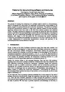
pair of actions element of the strict-time relation. Figure 2 shows two strict-time ordered actions with ∆Ta1 →a2 = 1 .
ε =2
Figure 3: Weak-Time Ordered Actions Figure 3 shows two weak-time ordered actions with ∆Ta1 →a2 = 1 and ε = 2 . The diagrams clearly show
→ is more abstract than that wt
that →⊆ st
st → in the sense
wt → , with ε = 0 in the strict case.
ASCET-SD MODELS The introduced modeling concepts can be realized within the tool ASCET-SD by using offered structural and behavioral modeling techniques (cf. Figure 4). One crucial point is the realization of a purely event driven semantics which is independent from a technical oriented system clock resp. scheduling sequences. For this reason ASCET-SD models are split into two layers. The upper one is called model layer and contains the intrinsic system specification whereas the lower one, called infrastructure layer, contains a framework for the provision of the event driven concept. The Model Layer
a1
∆Ta1 → a2 = 1
a2 Figure 2: Strict-Time Ordered Actions Weak-Time Conditions (s. Figure 3) are used to specify timing conditions which have to be met within a time slice. For temporally ordering actions in a weak manner wt → ⊆ Action × Action is introduced as follows:
(a1 , a2 ) | a1 → a2 → = ∧ ST (a1 ) ≤ ∆Ta1 →a2 − ε ≤ ST (a2 ) ≤ ∆Ta1 → a2 + ε wt
∧∆Ta1 → a2 ≥ 0 ∧ ε ≥ 0
Within the model layer an event driven semantics is used. Although a technical system clock is needed for executing computations the behavior is dependent on received events. Communication is handled via event exchange. Actions are performed by using ASCET-SD methods within classes or statemachines. The names of actions resp. events are prefixed with the label snd (send) and rcvd (received) (s. Figure 4(a)) to indicate whether the action resp. event is generated within a computation or it is requested within a condition. Computations are formulated as ESDL expressions, which are associated with actions at transitions and entry/static/exit actions at states. The activation of actions is realized by means of ordinary method calls. Actions are active as long as their computation does not fulfill a predefined postcondition or as long as they are
1/reset initValue/reset
1/out
memory
in/compute
return/out
1/compute
dT
A/out 1/out
memory x/out
return/out
K/compute B/out
(a) Actions/Events as Methods
(b) Algebraic Expressions
0/-
(c) Boolean Expressions
3/rcvd_BDC_Stop
BDControl
return/rcvd_BDC_Stop
1/snd_BDC_Start 1
2
2 0/-
3/rcvd_BDC_Start
BDControl
BDControl 1/snd_BDC_Stop
return/rcvd_BDC_Start
BDControl 1/snd_BDC_Reset
0
BDControl
1
(d) Ports as Variables
(e) Detection of Actions/Events
(f) Generation of Actions/Events
Figure 4: Representation of the Action Language in ASCET-SD (Model Level + Infrastructure Level) not explicitly terminated. Explicit termination can be carried out by arbitrary actions using the generic reset() method. Algebraic Expressions are commonly modeled within blockdiagrams (s. Figure 4(b)) by using a subset of constructs for visually displaying control algorithms. The depicted diagram corresponds to the formula in ∗ K ∗ dT + memory which conforms to the textual grammar definition (s. Figure 1). Simple algebraic expressions can also be formulated in ESDL analogously as stated above. Those expressions can be used e.g. as actions at transitions or as entry/static/exit actions at states. Boolean Expressions are responsible for managing the control flow of the system. They are usually modeled as conditions at transitions. In ASCET-SD there are two ways for depicting boolean expressions. (1) They can be defined textually with ESDL and (2) they can be visually modeled with blockdiagrams (s. Figure 4(c)). The depicted diagram can alternatively being represented in the action language as A ≤ x ∧ x ≤ B . The Infrastructure Layer In ASCET-SD modeled functions can only be realized at a single ECU. Within each ECU several concurrent tasks are being executed. So one has to define ASCET-SD
modules and a scheduling between them. The communication between modules is based upon pure data flow. So the representation of actions/events as methods on the model layer is not possible. At the infrastructure layer actions/events are represented as unsigned discrete variables (s. Figure 4(d)). Therefore a set of actions is grouped and each action is assigned with a unique id. If none of the actions is present the variable is allocated with 0, otherwise it contains the unique id of the action. Action Detection. The presence of actions resp. events and the related execution of operations can be checked by evaluating boolean conditions. Every action is associated with an ASCET-SD diagram containing a predefined boolean expression for detecting its presence. The boolean condition can be automatically generated from more abstract AML models such as the UML representation. During the evaluation of the condition the value of the associated variable is being analyzed (s. Figure 4(e)). An action/event is present if the variable is allocated with the unique id of the action. Otherwise the action/event is not present. Action Generation. Actions/events are activated during the execution of a state transition. They are invoked analogously to method calls (already described at the model layer). With each invocation the associated variable is allocated with the unique id associated to an action (s. Figure 4(f)).
ABSTRACTION LEVEL FUNCTIONS After the introduction of the AML model framework this section shows an application with respect to a simple, but realistic case study. Besides the example the modeling concepts of the AML applied at the function abstraction level are explained. The example includes a fragment of functionality within the body electronics of a car, namely the window lifting system. The case study reflects domain-specific requirements such as signal and functional dependencies with other control functions, timing constraints, the existence of variants and multiple deployments to different ECUs. THE WINDOW LIFTING CONTROLLER A simplified software control model for rising and lowering the window pane shall demonstrate the concepts of architecture modeling and the subsequent refinement steps necessary to run the software on an ECU network. The control software operates the window pane by opening and closing it. The opening and closing movement is performed by a motor with subject to the position of a control switch. The window lifting movement has to be stopped automatically when the lower or upper bound is reached. The window lifting function offers a normal operation mode, i.e. the control switch has to be pressed during operation. An additional automatic mode is provided to open or close the window until the physical limitation is reached. This may happen by pressing the switch for a very short time or by some comfort functionality in connection with the central locking system. MODELING STRUCTURED FUNCTIONS The AML is based on common characteristics of the above-mentioned automotive ADL research efforts. In AML functions play a central role. In contrast to ADL modeling concepts of components functions specify the type of components. In AML further an element/variant/ instance concept is used. Functions being basic building blocks may be tailored to product specific variants. These variants are instantiated. Instantiated functions can be compared with architectural configurations in standard ADLs. Hence functions are described at three characteristic levels. Element Level. The hierarchical structure of functions is used to locate each function easily. It also shows a composition relationship between functions that means each function can consist of several subfunctions. Signal dependencies between functions are depicted visually at this level. Functions serve as basic building blocks for
systems. That means that a function as a whole may also consist of redundant or contradictory subfunctions but cannot be implemented verbatim. Variant Level. To support a product line development approach functions can be tailored to variants. Variants are related to the corresponding function. A variant consists of a consistent subset of subfunctions. As a special case consistent functions, i.e. having no contradictory subfunctions, can be directly instantiated without explicitly creating variants in subsequent development steps. Instance Level. At the instance level variants resp. functions can be instantiated as often as they are needed within the overall system. At the instance level signal dependencies between instances of functions can be analyzed. These dependencies complement already specified dependencies at the element level. The respective diagram is called functional network. COVERAGE OF AML Using ASCET-SD notations for representing AML means to restrict the degrees of freedom offered by ASCET-SD modeling notations. Following the rough classification of ASCET-SD modeling techniques, an adaptation of classes is used for the representation of AML functions. Beyond this the logical system architecture is illustrated by modules and projects. Next to structural modeling elements, the behavioral description techniques are specifically tailored to fit the needs of the architectural description. AML MODELING CONCEPTS The case study is successively being presented according to the used AML modeling concepts. After a short summary of the meaning of the modeling concept, the case example is presented by using the UML and the ASCET-SD notation. By means of the concrete representation the advantages and disadvantages of UML and ASCET-SD are being discussed. The discussion follows three criteria: (1) semantic match, (2) visual expressiveness, and (3) completeness [14]. Meaning of Functions Functions are basic building blocks which organize the overall behavior into manageable pieces. The different pieces are structured as a hierarchical tree. So each function may be decomposed to further subfunctions. Functions use services of other functions of the same system. The communication between functions is done by signal passing. The signal dependencies of functions are represented as a connection between pairs of in- and outports.
MotorMovement [Movement] SwitchMovement [Movement] BOControl [Control]
BasicOperation
«environment» @DriverDoor
RLControl [Control] WindowControl [Control]
UsedMotorTime [Time]
RepetitionLock
MotorMovement [Movement]
BDControl [Control] Motor
UsedMotorTime [Time]
BlockDetection
SensorSignalsMotor [CurrentSignals]
Figure 5: Decomposed Variant DriverDoor of the Window Lifting Control Function (UML)
0/-
tick SwitchMovement MotorMovement
BOControl 3/Control
tick 1/tick
tick 2/tick
SwitchMovement 2/SwitchMovement
SwitchMovement 1/SwitchMovement
SwitchMovement MotorMovement 1/MotorMovement WindowControl 2/Control
BOControl
tick SwitchMovement SwitchMovement 2/MotorMovement MotorMovement MotorMovement WindowControl
WindowControl
BasicOperation
a_DriverDoor
tick 3/tick RLControl 4/Control
tick
6/Control
RLControl RLControl
UsedMotorTime 1/UsedMotorTime UsedTime 2/UsedMotorTime
UsedMotorTime UsedTime OperationTime
SensorSignals 1/SensorSignals measured_I 2/SensorSignals UsedMotorTime 4/UsedMotorTime UsedTime 5/UsedMotorTime
old Control1 Control2 Control Control3 Join
RepetitionLock
OperationTime 3/UsedMotorTime BDControl 5/Control
WindowControl
tick 5/tick
tick 4/tick BDControl
tick
tick
SensorSignals measured_I
SensorSignals measured_I BDControl
UsedMotorTime UsedTime OperationTime BlockDetection
MotorMovement MotorMovement 3/MotorMovement
UsedMotorTime UsedTime OperationTime Motor
OperationTime 6/UsedMotorTime
Figure 6: Decomposed Variant DriverDoor of the Window Lifting Control Function (ASCET-SD)
MotorMovement
Two different kinds of functions are differentiated: (1) Leaf functions and (2) Tree functions. Leaf functions represent elements at the bottom of the hierarchy of functions and execute specific control tasks. Tree functions may contain glue code dealing with e.g. scheduling sequences, data-exchange, or signal priorities [8]. This glue code specifies functional dependencies between subfunctions. The clue code itself is considered as a special leaf function in the following. In general the synchronization is performed by activation and deactivation of functions. Tree functions and their use within system specifications can be compared with “controllers” in the subsystem pattern and the recursive control pattern which are applied in common software engineering methods such as SA/RT and UML-RT [26,27]. AML tree functions are similar to controller functions of the recursive control pattern since in both modifications of the control signals are allowed. Signal dependencies between functions are defined by the use of connectors and ports. Dependencies within subfunctions are classified into a horizontal signal flow and a vertical signal flow. Top-level functions include the entire functionality of the implemented application. Since in the automotive domain software resources are always allocated statically and dynamic instantiation is not used, all connectors can be resolved at compile time. UML Representation of Functions The UML offers a broad variety of visual modeling constructs for representing functions or components. A good survey of all reasonable possibilities can be found in [14]. We have chosen to use classes for representing AML functions for several reasons. For clarity reasons classes are mostly shown in a folded state. Hence this kind of class visualization hides information about (private) attributes and methods. Each defined function can be decomposed into a set of subfunctions using hierarchical class diagrams. ASCET-SD Representation of Functions Within ASCET-SD leaf functions are represented as classes. Those classes can be refined with a behavioral description by using modeling concepts offered by blockdiagrams and statemachines. Tree functions are mainly used for specifying an appropriate function hierarchy. Tree functions are represented as classes again capable of showing the communication structure of the subfunctions (together with its “glue code”). An appropriate folder hierarchy is used to display the hierarchical structure even at the model browser level. This folder can also be used to store further diagrams which are related with the function. The Example Figure 10 shows the decomposition of the WindowLifting Control Function. This function offers basic functionality for operating the window lifting system.
The signal dependencies between functions at the same level of hierarchy are drawn directly in between the functions. To show vertical signal dependencies an element symbolizing the environment is introduced. Its name is @WindowLifting. Signal dependencies between functions and the symbolized environment state the propagation of signals to other functions located at a different level of hierarchy. In the case example there exists a function ComfortFunctions at the same hierarchical level of WindowLifting requiring signals from WindowLifting. Note that both tree functions are not visible within the shown figures. Signals delegated from ComfortFunctions to subfunctions of WindowLifting are drawn between @WindowLifting and BasicOperation (s. Figure 10 and Figure 5). Figure 6 shows the same functions as Figure 5 in ASCET-SD notation. In contrast to Figure 10 both diagrams only contain a subset of control functions. This subset constitutes a variant of WindowLifting (s. Figure 9). The modeling concept of a variant is discussed in detail in subsequent sections. Analogous to functions the glue code is located in a separate function called a_DriverDoor. Further a technical class named Join is needed. This class and the meaning of signal dependencies are described below. Meaning of Ports Functions are encapsulated from their environment by means of interfaces. In AML, interfaces are modeled as ports. Each inport owns the role of a service access point and permits the access to a service the function is offering or else it states the services the function requires from other functions. Services are fulfilled by sequences of actions. Modeling Language
AML
UML 1.4
UML-RT
Level 3
Port
Interface Class
Port
Level 2
Action
Method
Method
Level 1
Parameter
Parameter
Signal
Table 2: Comparison of Signal Concepts Signals are hierarchically structured. By regarding a concrete representation (UML/ASCET-SD) of the signal concept we restrict ourselves to three levels of hierarchy (s. Table 2). The first level of signals describes data values resp. parameters. The second level comprises entities (actions) which can be exchanged between two adjacent ports and correlate with method specifications in object orientation. Those level 2 signals may contain level 1 signals that correlate with parameters of methods in object orientation. At the third level several second level signals are composed to a port type. In AML multiple ports of the same port type can exist within the interface of a function.
Actions are level 2 signals. Actions that can be observed at inports are called received events. Actions that can be observed at outports are called sent events. At a given time only one event is allowed to be present at one port. So each port reflects the current demand for the execution of an action or the current execution of exactly one action. Actions themselves consist of two parts. A static one describing the signal structure in terms of a level 2 signal. This static description is the prerequisite for the dynamic description describing the execution sequence of actions. In AML events can be compared with method calls in object-orientation having as a rule no return values. Therefore, the methods have the same meaning as UMLRT methods. The aggregation of all methods (or signals), offered at inports or being incorporated at outports, establishes the possible signal-set being transferred by a connector. TimingSignals
representation suffers from two severe drawbacks [6]: (1) multiple ports of the same signal type cannot exist and (2) lollipops only show the signals offered (inports) and not required services (outports). To overcome both problems several solutions are proposed in literature. Unfortunately the stated solutions do not conform to the current UML 1.4 standard [22]. The first drawback was treated by attaching the name of the signal type at the end of the port name. So we can at least separate conceptually between different ports of the same signal type. Of course this leads to a slightly different interpretation of the lollipop shortcut. Now the lollipop shortcut looses its meaning as an inheritance relationship between the interface class specified by the lollipop name and the inherited class. Therefore our semantics of the lollipop construct is defined in the following way. The inherited interface class inherits the methods which obtain a new qualified name. Therefore an interface specification can be used multiple times by different classes. Considering the one-sided representation of ports we omit searching for a solution to this problem. Although we are convinced that a representation of inports and outports is essential for specification of functions we can extract the missing model information by looking at inports and the dependency relationship drawn. In the upcoming UML 2.0 standard [28] this severe drawback seems to have been solved.
OperationTime(Time:Real) UsedTime(Time:Real) DelayedTime(Time:Real) dT(Time:Real)
«variant» UsedMotorTime
ASCET-SD Representation of Ports OperationTime(Time:Real) UsedTime(Time:Real)
Figure 7: Formation of Variants – Signal Tailoring Specified signals can again be tailored to variants. The tailoring mechanism works analogously to the tailoring mechanism of functions. Figure 7 shows a signal framework with the name TimingSignals containing 4 methods. This signal definition can be instantiated to ports allowing the transfer of 4 different time values: Operation_Time, Used_Time, Delayed_Time, and dT. In the case example the signal definition of TimingSignals is too complex. The functions BlockDetection and RepetitionLock only need a subset of methods, namely OperationTime and UsedTime (s. Figure 6). To avoid over specified signal definitions, the AML allows the definition of signal variants as well. UsedMotorTime is a variant of TimingSignals which is specifically tailored to the signal needs of the WindowLifting function. UML Representation of Ports Again the UML offers a variety of visual constructs for modeling ports. In alignment with other architecture driven approaches we represent ports as interface classes symbolized as lollipops. Actually this kind of port
In contrast to UML the ASCET-SD provides two low level modeling concepts for ports: (1) methods model “inports” of classes and (2) message resp. variables model “inand outports” of modules and classes. In ASCET-SD ports are represented by diagrams within statemachines and classes. Since diagrams are only a syntactic structuring mechanism for methods ports are not visible at a black box view of a statemachine resp. class. Therefore in- and out-variables with the port name are introduced to interconnect different functions. At each variable each method of a port is uniquely addressed. For implementation purposes each event is encoded by a natural number. If an event is present the port variable is assigned with the according action’s unique id. If none of the contained actions is present, the port variable is assigned with 0. The Example Figure 5 shows the function WindowLifting responsible for the basic motor algorithm to control one window. It provides services for handling the commands of a switch for a door by means of SwitchMovement which has signal type Movement, appropriate handling if the window reaches the lower limit of the door frame or the upper limit of the roof with BDControl of type Control as well as means to use the actual motor current at the inport SensorSignalsMotor of type SensorSignals being measured by the Motor
function. The services of the component offered are shown in the lollipop notation, e.g. including requests to drive the motor in the appropriate direction and to deliver a maximum current, measured during a given time. Figure 6 shows the ASCET-SD model derived from the UML model. Interface classes resp. signals level 3 (ports) are not available in ASCET-SD, the modeling of in- and outports is more fine grained. For example a port of type TimingSignals (cf. Figure 7) contains four methods, a variant of this signal definition is used at function BlockDetection (s. Figure 6). Comparing the UML and the ASCET-SD visualization, the ASCET-SD visualization is capable of representing both inports as well as outports. But analogously to the UML representation the diagram mechanism for representing ports fails to model multiple instances of the same signal type. In ASCET-SD the method names are prefixed with a unique abbreviation of the port name. Meaning of Connectors Connectors are used to relate pairs of in- and outports. Each pair of connected ports must harmonize. The notion of harmonization is expressed by a signal subset relationship between in- and outports. Outports are only permitted to send events residing on a subset of signals which the inport is capable to understand. Using a client/server interpretation of functions, a port providing service access ports is called a server-port whereas a port requiring a service is called a client-port. However, a port’s role is associated by drawing connector dependencies between ports. The aggregation of all actions (or signals), offered at an outport or being incorporated at an inport, establishes the signal-set being transferred by a connector. Ports can be connected in three different ways. (1) Peer-to-Peer. A pair of connected ports is unique in the sense that each outport has exactly one inport as a unique counterpart. (2) Multicasting. One outport is connected with several arbitrary inports (Multicasting). If the signal is routed to all functions within one level of hierarchy, we speak of local broadcasting. (3) Multi-Source. Analogously one inport can be connected with multiple outports. In this case various sources for one received signal exist. This leads to signal interferences which have to be resolved. Therefore we propose the use of a join component which integrates different streams of signals. Arising conflicts are resolved by a context-sensitive strategy. From a methodical point of view multicast communication is typically used for signals being used by several clients in the vehicle, e.g. the vehicle voltage, the clamp-state or the vehicle’s actual velocity.
Within the AML modeling concepts a horizontal and a vertical signal flow are differentiated. •
The horizontal signal flow denotes the interactive communication of functions being direct subfunctions of the same function so that they are within one level of the functional structure.
•
The vertical signal flow denotes the communication between two levels of the functional structure (as stated above). Depending on the communication direction the vertical signal flow is called delegation resp. propagation. Delegation denotes the flow of signals from a function down to the composed subfunctions, whereas propagation denotes the opposite direction of the signal flow.
Due to the symmetry of modeling concepts and due to the introduction of an element depicting the environment, the horizontal and the vertical flow of signals can be identically represented as UML dependency arrows. UML Representation of Connectors For the representation of ports as lollipops we have chosen the dependency relation to provide an appropriate mechanism for stating inter-functional signal dependencies. Using dependencies within UML an abstract view of connectors is given. A more technical view is necessary within ASCET-SD to generate executable models, especially in the case of multi-source communication. Whereas in UML the technical-oriented join components are not explicitly specified. ASCET-SD Representation of Connectors In ASCET-SD in- and outports are connected by regular communication connections. Considering the case of a multi source communication a join component resolves conflicts between different signals. A predefined strategy is hereby applied. The Example Figure 5 and 6 show examples for the representation of connectors in UML and ASCET-SD. The communication between Motor and BlockDetection over the inport SensorSignals of type CurrentSignals is a simple Peer-to-Peer connection. As there are several different functions which are responsible for stopping the window movement the inport WindowControl is the target of a Multi-Source communication. The window movement has to be stopped if an external stop event is occurring, if the block detection detects that the upper or lower limit has been reached, or if the repetition lock wants to stop the motor to avoid overheating due to repeated operation of the motor. Therefore a join component for the signal type Control is only modelled in ASCET-SD, not in UML. This technical component just prioritizes different signals. Those join components can be generated from lists with signal priorities.
S Disabled/ tick [rcvd_SS_Amperage() && I>=I_EinMax-2] /snd_BDC_Stop
1
tick [rcvd_BDC_Stop]
tick [rcvd_BDC_Stop]
tick [rcvd_BDC_Start]
1 Observation/ 2
2
1
Calibrating/ Entry: I_EinMax=5; Static: if (rcvd_SS_Amperage() && I>I_EinMax) {I_EinMax=I;}
tick [rcvd_UMT_UsedTime() && Time>=0.22]
Figure 8: Behavioral Specification of the Window Lifting Control Function (ASCET-SD) MODELING THE BEHAVIOR OF FUNCTIONS The behavior of functions has to be completely specified for building up realizable system models. Since vehicles are safety critical systems, it is wise to use system theoretic modeling means like finite state machines or control engineering block diagrams to design control algorithms. To bring the design down to an ECU, a more software oriented modeling is crucial, e.g. to make use of a element/variant/instance concept while keeping the advantages of graphical descriptions. A tool providing this dedicated automotive control software view is ASCETSD. The modeled system behavior will be measured against specified performance criteria. During the analysis and design phase, the performance criteria of a control algorithm have to be checked by means of analysis, simulation, and target experiments. Modeling Concepts for Dynamic Behavior Function behavioral refinement means to add behavior to functions. The function’s interfaces have to match the input- and output signals used within the control algorithm. The element/variant/instance concept of the AML can only be kept during the step of component refinement by using these concepts for behavioral modeling too. Furthermore, the method-like signals of the AML’s signal-set should have a direct counterpart in the control-algorithm. Thus, the behavioral class concept described below forms the conceptual basis for function refinement. Statemachines [16] contain an operational specification of the execution of actions. With a statemachine the set of all action traces can completely be specified. In general those actions are executed within states whose
execution time takes up some period whereas short time actions and events are executed at transitions. Within ASCET-SD statemachines resp. classes the communication between them is driven by means of asynchronous method calls, i.e. by calling a method of the other classes. In a behavioral class the execution sequence of statements is given by the order of the statements. A method is a sequence of statements realizing Boolean and arithmetic expressions as well as method calls to aggregated objects. Control structures like loops and selections constitute a powerful programming language. Semantic Definitions When finalizing the complete behavioral specification we can yield profit by checking the complete specification against the defined causal ordering of actions. Both the formal semantics of the action language and the formal semantics of the statemachine are defined as a mapping to the same minimalist model structures only structured by actions. If both model structures coincide the statemachine correctly realizes an action structure. FORMATION OF FUNCTIONAL VARIANTS In the automotive domain the methodical support for the development of product lines becomes more and more important to meet development needs of products sharing a large set of common properties. Industrial and scientific approaches to product line development are usually centered on architectural entities. The AML includes the modeling concept of a variant which is applicable to all different kinds of architectural entities included in the language definition to support a product line development approach.
This section reveals the use of the modeling concept variant applied to functions. For the development of product lines similar functionalities with different realizations or features are considered. So one concrete realization is characterized by its individual features. Within a product family different realizations with very similar features exist only differing in few features. In AML a function collects the description of functionality in the mentioned sense. So a function contains the description of all different features of product family. Features are described again by functions. A function may contain contradictory functions specifying feature descriptions. During a development process functions are treated as generic frameworks on the element level. So functions contain the building blocks with which a system is realized. Therefore functions can be tailored to specific variants. In the case study the function window lifting represents such a framework. The functions DriverDoor and PassengerDoor (s. Figure 9) are variants of WindowLifting. Within WindowLifting all needed functionalities for specifying the possible variants are summarized. From a methodological point of view the framework serves as a source for reusing activities within different parts of the system model or different products. The framework itself contains specifications of all possible subfunctions and their signal dependencies. For reuse purposes the whole framework can be taken or only a fragment. Each fragment constitutes a variant. Since variants are realized and instantiated within the system they have to be consistent. Consistent functions are instantiated as well if the specified function is the only reasonable variant. This shortcut eases the modeling process and keeps the specification lean. SwitchMovement [Movement] WindowControl [Control] WindowLifting
«variant»
SwitchMovement [Movement]
For the definition of families of functions, the AML provides a variant dependency. The variant dependency states the relationship between the function and all of its variants. In addition to the definition of families of functionalities, the concrete tailoring of a function to the different variants has to be defined. Representation of Variants In UML the relationship between a function and the associated variants is represented by a dependency arrow with the stereotype (s. Figure 9). The representation in ASCET-SD lacks of the explicit statement of this dependencies at the model level. The association can be derived by exploiting the hierarchical folder structure. Each variant is stored in the folder belonging to the tailored function. As ASCET-SD shows the realization of a concrete ECU within ASCET-SD only variants (and functions) which are instantiated are shown. Both in UML and in ASCET-SD the selection of concrete subfunctions constituting the variant is done in the same way as it is done by the definition of the functional structure and as it is described in the previous sections. If subvariants instead of subfunctions are selected, those have to be defined before with the same mechanisms. Adjusting Functional Dependencies Analogously to the specification of the function, the functional dependencies (glue code) between the selected subfunctions have to be specified. Again these dependencies are collected in a controller function. The name can be derived from the name of the variant by prefixing the string “a_”. Generally the functionality of the variant controller is some kind of sub functionality resp. it is some kind of refinement of the function’s controller. Reconfiguration of Interfaces
«variant»
WindowControl [Control] DriverDoor
Tailoring of Functions
WindowControl [Control]
PassengerDoor
SwitchMovement [Movement]
Figure 9: Formation of Variants – Function Tailoring
Since variants select only a subset of functions, the interface declaration of variants has to be adapted to the specific signal needs of the variant and cannot be taken directly from the framework specification. Again the ports of the variants, which constitute the interface specification, are in a subset relationship with the ports of the function. Additional variant of the ports of the function may be used. The specification of variants of ports is similar to the specification of variants of functions (cf. Figure 7).
MotorMovement [Movement]
SwitchMovement [Movement] BasicOperation
BOControl [Control] WindowControl [Control]
CPControl [Control]
«environment» @WindowLifting
ChildProtection MotorMovement [Movement]
RLControl [Control] RepetitionLock
UsedMotorTime [Time] Motor BDControl [Control]
BlockDetection
UsedMotorTime [Time]
SensorSignalsMotor [CurrentSignals]
Figure 10: Decomposed Window Lifting Control Function (UML) 0/SystemControl
tick 1/tick
tick 4/tick
tick 0/SwitchFrontLeft
tick 0/-
SwitchMovement SwitchMovement WindowLiftingFrontLeft MotorMovement MotorMovement Control WindowControl SensorSignals
SwitchFrontRight
MotorFrontLeft 3/Motor
UsedMotorTime
SensorSignals 2/tick
SwitchMovement SwitchMovement WindowLiftingFrontRight MotorMovement MotorMovement Control WindowControl SensorSignals
UsedMotorTime 3/tick
SwitchMovement 3/Switch
SwitchMovement 2/Switch
SwitchMovement 4/Switch
tick 7/tick
WindowControl 2/Control
SwitchBackLeft
tick 10/tick
WindowControl 4/Control
tick 0/-
SwitchMovement SwitchMovement WindowLiftingBackLeft MotorMovement MotorMovement Control WindowControl SensorSignals
UsedMotorTime 6/tick
MotorMovement Control 4/Motor 3/Control
tick 0/-
UsedMotorTime
SensorSignals 5/tick
SwitchMovement MotorMovement Control 1/Switch 1/Motor 1/Control
MotorFrontRight 6/Motor
SwitchBackRight
MotorBackLeft 9/Motor
UsedMotorTime
SensorSignals 8/tick
UsedMotorTime 9/tick
SwitchMovement SwitchMovement WindowLiftingBackRight MotorMovement MotorMovement Control WindowControl SensorSignals
UsedMotorTime
SensorSignals 11/tick
UsedMotorTime 12/tick
SwitchMovement MotorMovement Control 5/Switch 7/Motor 5/Control
SwitchMovement 7/Switch
SwitchMovement 6/Switch
SwitchMovement MotorMovement WindowControl 8/Switch 11/Motor 8/Control
WindowControl 6/Control
Figure 11: Functional Network of Window Lifting Control Functions
MotorBackRight 12/Motor
Control 7/Control
THE FUNCTIONAL NETWORK The functional network supports the collaboration of different development teams. With the growing complexity of the implemented systems, some well used practices exhibited some severe drawbacks. In the past, functions were developed in isolated development teams within one company. This worked well as long as the functions fulfilled their task in isolation. With the increasing number of functions and the growing amount of interactions, integration of these functions failed. Problems like side effects and timing latencies aroused. To over-come the difficulties of a distributed development of functions, the AML introduces the functional network (s. Figure 11) to compose different functional specifications to support the communication process between different development teams in order to gain an understanding of the mutual dependencies between functions. Instantiation At the functional network level the specified variants (and maybe those consistent functions with no variant) are instantiated as often as they are needed to fulfil control tasks in the overall system. At this level functions from different development teams can be composed together to validate their interoperation. By doing this the development of correct and interoperable functional specifications is supported at the functional level. This facilitates the realization of interacting control units at the technical level. Determining Signal Dependencies When composing different functional instances, signal dependencies between those instances have to be specified. This information cannot be gained from the specification of signal dependencies at the functional level. The missing information has to be added to the system model when building the functional network. The added information is complementing the signal dependency specification at the functional level. In ASCET-SD instances of the specified variants are again being composed at the class level. This ensures the greatest flexibility for the construction of the logical system architecture. Similar to the above described functional level, the signal dependencies are stated by the connection of in- and outport pairs.
LOWER LEVEL ABSTRACTIONS As described above, tree functions aggregate further functions and glue-code, the latter implementing a controller. However, timing requirements of the actions as well as the location of sensors/actuators impose constraints on transforming the tree functions into a technical architecture. For example, some sensors are sampled more often than used by the control algorithm. Thus, the sensor “filtering” algorithm will be allocated to a functional cluster
with a higher cycle time. Since the sensor algorithm might now interrupt the control algorithm, simple data exchange in the glue-code of tree functions does not work, i.e. the data-exchange has to be thread-safe. ASCET-SD is offering thread-safe communication by means of modules. Modules are embedded real-time modeling primitives offering processes and messages. Modules can only be instantiated once. •
Threads are given by an OSEK-task; the latter will call void-void functions while being active. Processes are void-void functions being activated within an OS-Task. They read data from so-called messages, perform some computations, e.g. by calling methods of classes, and write back data to messages. Method calls to classes running in another thread are prohibited by ASCET-SD.
•
Messages are simple IPC constructs based on global variables if there is no tentative task interruption or there are no double-buffered variables in case of a tentative task interruption. The latter mechanism ensures that the data values read after an interruption are the same as before the interrupt occurs. Of course, double buffering requires a copy step prior to each activation of the task. The necessity of double buffering is determined by offline calculus [24].
From the AML-point of view this means that a FunctionalNetwork has to be mapped to a network of Threads and ECUs. As described above the communication between classes is realized by variables which can be directly used within messages of modules. In this way some functions can be clustered to thread safe units which are realized by modules in ASCET-SD. ECU-BASIC TECHNICAL COMPONENTS Currently, the preferred technology for inter ECUcommunication is the CAN-Bus. Typically, a communication matrix determines which CAN-frames are received by an ECU, the CAN-frame’s cycle time as well as the application signals are the CAN-frame carriers. In automotive electronics it is not feasible to use one CANframe for one application signal. CAN-drivers are part of so called-ECU basic software which often is configured by the vehicle manufacturer, e.g. the Standard Core of BMW. FUNCTIONAL CLUSTER Functional Clusters are tightly coupled instances of functions and subfunctions running sequentially in one thread. The order of events occurring in a functional cluster is given by a caller/callee relationship of components. This ordering can be expressed by interaction diagrams of the UML. In ASCET-SD the ordering is achieved by so called sequence-calls of methods.
DEPLOYMENT OF FUNCTIONAL CLUSTERS In a deployment step, several instances of functions of a functional network might be assigned to a functional cluster. Sub-trees of tree-functions can be assigned to functional clusters too. At the boundary of a functional cluster, the dataexchange has to be mapped from simple data elements to module messages within ASCET-SD. As the mapping of different levels of signals on data values is already done for the mapping of functions and variants to classes the mapping is now straightforward. Second level signals, i.e. methods having formal parameters are translated to several messages containing the parameters. The method itself is coded to a message which may contain all possible events of the according third level signal, i.e. the interface. In this way the event mechanism is translated to message flow. Making those event transmission thread-safe resembles to the server stubroutines in TITUS [10]. After mapping instances of functions to functional clusters and functional clusters to ECUs a connector might span between different ECUs. From the CANframe point of view, a connector realizes an application signal in a CAN-frame. The application of the signal is determined as follows: Third level signals. Only formal parameters of first and second level signals are considered, i.e. merely the resulting signal-flow is used. While the system is active the actual parameters of the methods constitute the systems signal-flow. Second level signals. Binary coding of the number of signals (methods) in one interface. The resulting bit pattern is called method-indicator. First level signals. The length of the method indicator plus the maximum of the bit-width of all formal parameters per method over all methods. E.g. an interface consisting of two methods, one without formal parameters and one with one unit8 formal parameter requires nine bit, the first bit indicating the chosen method whereas the remaining 8 bits are only used to carry the actual parameter of the second method. If a first level event exists of only one method the leading method indicator bits will be omitted. The most flexible way of assigning functional networks to ECUs is by mapping instances of leaf functions to threads and ECUs. This radical approach as chosen for example in [10] requires a flattening of all tree functions to an instance list. All propagation and delegation connectors are resolved too. Each leaf function is then embedded in an ASCET-SD module. Event entry points are always mapped to processes and the data-exchange is always performed thread-safe by ASCET-SD messages. The flexibility offered by an arbitrary allocation of modules to threads and ECUs is paid by introducing tentatively
unnecessary messages and by the mapping to event entry routines. The AML way of mapping is more adaptable. As it only generates thread-safe modules where they it is needed. It may lead to smaller and faster code generated from the ASCET-SD models. The price to be paid is that functional clusters have to be specified on a more abstract modeling level. Afterwards the instances of functions may not be reused within ASCETSD as they are realized by classes and reuse w.r.t ECU/Task allocation within ASCET-SD is based upon the usage of modules. As all relevant functionality except technical glue-code, which may be generated, is realized by classes one has to use the complete AML tool chain for reuse.
CONCLUSION Motivated by the aim to meet the challenges of developing automotive embedded real-time software we have presented an architecture centric modeling language and its representation in UML and ASCET-SD. The focus was set on the abstraction level functions within the AML proprietary system of abstraction levels. Functions serve as a collection point of different features which are necessary for the realization of different product lines. The specification of product lines provides an attraction especially in the area of automotive software development. In the automotive domain typically several realizations of similar functionality have to be developed and maintained. For this reason the AML uses an element/variant/instance scheme to address these specific development needs. Further we have shown how abstract architecture models of embedded software can be translated into more technical models. The AML uses the standard and wide spread modeling language UML for the representation of the software architecture with the focus on embedded systems. Together with the definition of functional clusters which are capsules for functional instances, a translation of an abstract architecture model into an implementation model in ASCET-SD is given. The presented work is used within the research project AUTOMOTIVE for the idea of a model-based tool chain including three tools: Telelogic DOORS, Telelogic UML Suite, and ETAS ASCET-SD. These tools are conceptually tightly linked together with the definition of the AML metamodel containing model elements represented at least in two tools. The AML also defines a modeling style which must be used within each tool to translate models between them. Based on our research efforts we think that a seamless model-based development process is feasible in the next years. A seamless and integrated modeling approach is a prerequisite for the development of embedded software for control units and for the maintenance of correct, consistent, and complete specifications this software.
ACKNOWLEDGMENTS We thank Andreas Lapp and Bernhard Schätz for carefully reading draft versions of this paper. We are much obliged to our colleagues of the project Automotive for many fruitful discussions; in particular Werner Baumgarten and Bernhard Wimmer. We thank Manfred Broy for directing this research. This work has been partially funded by the Bayerische Forschungsstiftung (BayFor) within the Forschungsverbund für Software Engineering II (FORSOFT II).
REFERENCES 1. ASCET-SD User's Guide Version 4.2; ETAS GmbH; Stuttgart; 2001. 2. Michael von der Beeck, Peter Braun, Martin Rappl, and Christian Schröder: Modellbasierte Softwareentwicklung für automobilspezifische Steuergerätenetzwerke, VDI-Berichte, Nr. 1646, S. 293 ff., 2001. 3. S. Boutin: Architecture Implementation Language (AIL); 1er Forum AEE; Guyancourt; March 2000; http://aee.inria.fr/forum/14032000/SB_Renault.pdf. 4. Brodsky, Clark, Cook, Evans, and Kent: Feasability Study in Rearchitecting the UML as a Family of Languages Using a Precise OO Meta-Modeling Approach, The pUML Group, 2000. 5. Manfred Broy ++: The Design of distributed Systems, An introduction to FOCUS – Revised Version, Technical Report, TUM-I9202, Technische Universität München, 1993. 6. Manfred Broy, Michael von der Beeck, Peter Braun, and Martin Rappl: A fundamental critique of the UML for the specification of embedded systems. 7. J. Eisenmann et al.: Entwurf und Implementierung von Fahrzeugsteuerungsfunktionen auf Basis der TITUS Client Server Architektur; VDI Berichte (1374); pp. 309 – 425; 1997; (in German). 8. Pio Torre Flores ++: Integration of a Structuring Concept for Vehicle Control Systems into the Software Development Process using UML Modeling Methods, SAE Technical Paper Series 2001-010066, Detroit, 2001. 9. Ulrich Freund and Alexander Burst: Model-Based Design of ECU Software – A Component-Based Approach. IN OMER LNI, Lecture Notes of Informatics, GI Series, 2002. 10. U. Freund et. al.: Interface Based Design of Distributed Embedded Automotive Software - The TITUS Approach. VDI-Berichte (1547); pp. 105 – 123; 2000. 11. Maximilian Fuchs and Dieter Nazareth: Ein BMWExperiment zur Verbesserung des Steuergeräte Entwurfprozesses mit ASCET-SD, In Proceedings Industrielle Software Produktion,13/14 November 1997, Messe Stuttgart International, Stuttgart,1997. 12. Maximilian Fuchs et al.: BMW-ROOM: An Object Oriented Method for ASCET-SD; SAE Paper 98MF19; Detroit; 1998.
13. David Garlan: Software Architecture; in Wiley Encyclopedia of Software Engineering,; J. Marciniak (Ed.); John Wiley & Sons, 2001. 14. David Garlan, Shang-Wen Cheng, and Andrew J. Kompanek: Reconciling the needs of architectural description with object-modeling notations. In Science of Computer Programming 44, P. 23-49, Elsevier, 2002. 15. Bernd Gebhard and Martin Rappl: Requirements Management for Automotive Systems Development; SAE 2000-01-0716; Detroit; 2000. 16. David Harel: StateCharts: A Visual Formalism for Complex Systems; Science of Computer Programming 8(3); pp. 231- 247; 1987. 17. Derek Hatley and Imtiaz Pirbhai: Strategies for real time system specification, Dorset House Publishers, New York, 1988. 18. Markus Hemprich, Mark-Oliver Reiser, Matthias Weber: "Die TITUS Modellierungsnotation und ihre Zuordnung zu UML-RT", OBJEKTspektrum 2/2001, S. 32-4 (in German) 19. Andreas Lapp et al.: UML Metamodel Extensions for Specifying Functional Requirements of Mechatronic Components in Vehicles, OMER – Object-oriented Modeling of Embedded Real-Time Systems, Lecture Notes in Informatics, GI Series, 2002. 20. Nenad Medvidovic, David Rosenblum, David Redmiles, and Jason Robbins: Modeling Software Architectures in the Unified Modeling Language, ACM Transactions on Software Engineering and Methodology, Vol 11, No .1, P. 2-57, 2002. 21. Nenad Medvidovic and Richard N. Taylor: A Classification and Comparison Framework for Software Architecture Description Languages, IEEE Transactions on Software Engineering, vol. 26, no. 1, January 2000. 22. Object Management Group: OMG Unified Modeling Language Specification, Version 1.4, September 2001. 23. Object Management Group: OMG XML Metadata Interchange (XMI), Proposal to the OMG OA&DTF RFP 3: Stream-based Model Interchange Format (SMIF), OMG Dokument, Oct 20th, 1998. 24. S. Poledna, Th. Mocken, J. Schiemann, and Th. Beck: ERCOS: An Operating System for Automotive Applications. SAE Conference, 1996. 25. Bernhard Rumpe and Andy Schürr: UML + ROOM as a Standard ADL?, Engineering of Complex Computer Systems, ICECCS'99 Proceedings, IEEE Computer Society, 2000. 26. Bran Selic, Garth Gullekson, and Paul T. Ward: Real-Time Object Oriented Modeling, John Wiley, 1994. 27. Desmond F. D’Souza and Alan C. Wills: Objects, Components and Frameworks with UML – the CATALYSIS approach, Addison-Wesley, 1998. 28. U2-Partners: Unified Modeling Language: Superstructure, version 2 beta R1 (draft), Revised submission to OMG RFP ad/00-09-02, http://www.u2partners.org/, 2002.
URLS 29. Homepage Automotive (FORSOFT): http://www.forsoft.de/automotive/ 30. Homepage BMW AG: http://www.bmw.de/ 31. Homepage ETAS GmbH: http://www.etas.de/ 32. Homepage Telelogic AB: http://www.telelogic.de/
CONTACT The authors’ addresses: Dipl. Inf. Dr. Michael von der Beeck BMW Group – Function Development Process Max-Diamand-Straße 13 D-80937 München
[email protected] Dipl. Inf. Peter Braun Munich University of Technology Department of Computer Science Chair of Software und Systems Engineering Boltzmannstraße 3 D-85748 Garching bei München
[email protected] Dipl. Inf. Dr. Ulrich Freund ETAS GmbH – Research and Development Borsigstraße 10 D-70469 Stuttgart
[email protected] Dipl. Inf. Martin Rappl Munich University of Technology Department of Computer Science Chair of Software und Systems Engineering Boltzmannstraße 3 D-85748 Garching bei München
[email protected]
KEYWORDS Abstraction Levels, Architecture Description Language (ADL), ASCET-SD, Automotive Modeling Language (AML), Software and Systems Engineering, Electronic Control Unit (ECU), Metamodel, Requirements Engineering, System Model, Unified Modeling Language (UML)