header for SPIE use
Architecture for computational mathematical morphology John C. Handley Digital Imaging Technology Center Xerox Corporation 800 Phillips Road, MS 128-25E Webster, NY 14580-9701 USA
[email protected] ABSTRACT We present a real-time, compact architecture for translation-invariant windowed nonlinear discrete filters represented in computational mathematical morphology (CMM). The architecture enables filter values to be computed in a deterministic number of operations and thus can be pipelined. Memory requirements are proportional to the size of the filter basis. A filter is implemented by three steps: 1) each component of a vector observation is used as an index into a table of bit vectors; 2) all retrieved bit vectors are “ANDed” together; and 3) the position of the unique nonzero bit is used as an index to a table of filter values. We motivate and describe CMM and illustrate the architecture through examples. We also formally analyze the representation upon which the architecture rests. A modification of the basic architecture provides for increasing filters.
1. INTRODUCTION Image processing in printers and digital copiers is done in hardware due to the immense flow of image data. Color and grayscale data at high resolution and increased printing speeds have obviated current binary image processing architectures. Nonlinear filters that use shape information are required in many document imaging applications. For example, lines and corners often need to be detected and enhanced. These operations are well-suited for nonlinear filters based on mathematical morphology. Due to cost constraints, architectures for nonlinear filters must be simple and memory efficient. Computational mathematical morphology (CMM) provides a representation of nonlinear filters that satisfies these constraints [1]. CMM decomposes a translation-invariant, windowed filter into a finite set of simple operations: testing whether a windowed observation is in an interval. If the result is affirmative, a value associated with that interval is returned. This representation is a search problem: find the interval to which an observation belongs. The comparator-based architecture of Dougherty and Sinha [2] performs these operations in parallel. While simple, there could be many intervals to test and this architecture may not be practical for many filters. For increasing filters, one must tally the intervals to which an observation belongs and take the maximum value associated with the intervals. Once again, these are easily conceived as parallel operations, but implementation in practice may be cumbersome. We present a different architecture for CMM, one inspired by search strategies. By pre-computing interval membership information, we can produce the proper interval in few operations. As with the comparator-based architecture, this method executes in a fixed number of operations, making it suitable for pipelining.
2. COMPUTATIONAL MATHEMATICAL MORPHOLOGY CMM decomposes mappings between lattices by partitioning pre-images or level slices of mappings into intervals. The endpoints of intervals serve as a basis. For increasing mappings, we need only the lower endpoints. Evaluating a mapping requires determining to which interval an observation belongs. Filters are designed by finding or estimating the best intervals relative to some criterion. CMM generalizes the binary case to gray in the following way. Consider a binary erosion example. We take the structuring element E = (1 1), shift it, and compare it to a windowed observation of the binary signal (bold indicates the origin). The value of the erosion is 1 at z if and only if E z ⊆ A ∩ Wz , where W = (1 1) . In indicator representation,
1, ε E ( A)( z ) = 0,
(1,1) ≤ ( x z , xz +1 ) otherwise,
(1)
where ( x z , xz +1 ) is the indicator representation of A ∩ Wz . In general, if the structuring element has N components E = (e1 , K , eN ) and the indicator representation of A ∩ Wz is x = ( xz , K , xz + N −1 ) , then
1, ε E ( A)( z ) = 0,
(e1 , K , eN ) ≤ ( xz , xz +1 , K , x z + N −1 )
(2)
otherwise.
Structuring element E and observation x are binary vectors. The set of N-dimensional binary vectors are partially ordered. If Eq. (2) works for binary signals, can it not also work in gray-scale? In fact, when components of E and x can take integer values between 0 and 255 inclusive, this is a form of an elemental erosion in CMM. The key property used here is that both the set of windowed binary observations and windowed gray-scale observations form complete lattices. That is, they are sets with a partial order and all subsets have least and greatest elements. In the binary case, (0,…,0) and (1,…,1) are least and greatest elements, respectively. The least and greatest elements for the gray-scale lattice are (0,…,0) and (255,…,255), respectively. The elemental erosion can be used to build more complicated filters. Let Ψ be an increasing function of windowed observations. A windowed observation of a gray-scale image can be represented as a vector of length N. Ndimensional vectors are partially ordered: x = ( x1 , K , xN ) ≤ y = ( y1 , K , y N ) if and only if xi ≤ yi for i = 1, K , N . The filter Ψ assigns a value to each observation: Ψ ( x ) = z . One of the simplest increasing operations is an N-elemental grayscale erosion,
1,
ε r ( x) =
r≤x
(3)
0, otherwise.
In morphological image processing, we think of gray-scale erosion as fitting a structuring element r underneath the signal x, raising it up has high as it will go and noting the height. Here we simply indicate whether or not r fits below x. −
If A is a subset of a lattice, let A denote its least elements. Define kernel sets K y ( Ψ ) = { x : Ψ ( x ) ≥ y} , y = 0,1, K . These
sets are decreasing in y: K 0 ( Ψ ) ⊇ K1 ( Ψ ) ⊇ K 2 ( Ψ ) ⊇ L .
(4)
An increasing filter Ψ has the following decomposition [2]: Ψ ( x) = max{ y : ∨ r∈K
− y
(Ψ )
ε r ( x) = 1} .
(5)
To visualize Eq. (5), consider the example in Figure 1 of an increasing filter operating on a two-pixel observation. 255
x2
2
1
4
7
3 4
0 0
255
x1
Figure 1. Geometric illustration of a two-pixel window increasing gray-scale filter.
In Figure 1, Ψ (16,13) = 1 , Ψ (254, 5) = 4 , etc. Kernel set K1 ( Ψ ) is the entire region. Sets K 2 ( Ψ ) , K 3 ( Ψ ) , K 4 ( Ψ ) , and K 5 ( Ψ ) = K 6 ( Ψ ) = K 7 ( Ψ ) are the shaded regions in Figure 2, respectively: 255
255
x2
2
1
4
x2
7
4
2
3
x2
7
4
2
3
1
x2
7
1
4 255
0
3 4
0
0
255
7
4
0
x1
4
2
3
1
4 0 0
255
255
255
0
x1
255
0
x1
x1
Figure 2. Shaded regions are kernels of the filter in Figure 1.
Consider the two-pixel observation x = ( x1 , x2 ) of an eight-bit image or signal marked on the diagrams in Figure 2. In each of K1 ( Ψ ) , K 2 ( Ψ ) , K 3 ( Ψ ) , and K 4 ( Ψ ) there is a vector less than or equal to x, namely x itself. In K 7 ( Ψ ) , there is no such vector. Therefore, 4 is the largest such value of y , thus Ψ ( x1 , x2 ) = 4 . The representation in Eq. (5) uses sets of minimal −
−
elements, K i ( Ψ ) . These are the lower left-hand corners of the shaded regions. Note that K 2 ( Ψ ) has two points and −
K 4 ( Ψ ) has three points.
2.1 Computational Hit-or-Miss Transform In CMM, when erosion and dilation are combined to form a hit-or-miss transform, the result is simply outputting a value when a windowed observation fits into an interval [2]. Let Ψ be a translation-invariant filter on a complete lattice, Ψ : L → M . The CMM hit-or-miss representation theorem is straightforward for finite lattices L and finite sets M of interest −1
in image processing. Let S k = {[lk , uk ], K ,[lk , uk ]} be a partition of Ψ ( k ) for each k ∈ M . Then, 1
{
1
Ψ ( x ) = k ∈ M : ∃ i such that x ∈ lk , u k i
nk
i
nk
} .
(6)
The gist of this is that sets of points of L that map to k are partitioned into intervals, sets having lower and upper bounds. Given an observation x, find the interval to which it belongs and report the value k corresponding to that interval. Obviously, −1
any finite subset of a lattice can be partitioned into intervals and there are many partitions S k of Ψ ( k ) , the pre-image of k. Finding the “i” in Equation (6) may be difficult. The architecture of Dougherty and Sinha [2] is a straightforward arrangement of parallel comparators: each interval is tested in parallel. This may not be practical for large expansions, which can occur for complicated pre-images. An alternative “bit vector” approach is given next. 2.2 Architecture for Hit-or-Miss Transform Consider an observation with N pixels values: x = ( x1 , K , x N ) . An interval is an ordered pair of vectors l = ( l1 , K , l N ) and u = ( u1 , K , u N ) with l £ u . A windowed observation x fits into interval [ l , u] if and only if l £ x £ u . In CMM, when an observation x fits into one interval in a set S = {[ l , u ]: i = 1, K , n } , a value associated with j is returned. By the hit-or-miss representation theorem, a set of interval sets S = {S j : j = 1, K , m} fully determines the actions of a filter: 1) in a window, j
i
i
j
observe x ; 2) check each set S j , j = 1,…,m for membership within an interval in the set S j ; 3) if there is a fit inS j , output the value associated with index j, otherwise output a default value. A sequential way to implement this algorithm is to search through the interval set searching for a fit. At worst, it will require checking all T =
å
interval, N checks of the form li £ xi £ ui . At best, a fit could occur on the very first interval.
m j =1
n j intervals, and within each
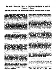
To gain intuition, we can view the gray-scale problem geometrically. Each windowed observation x is a vector in an Ndimensional space [ 0, K ,255] ´ [ 0, K ,255]´L´[ 0, K ,255] . Each interval [ l , u ] is a (hyper) rectangle in that space. A set of intervals S j = {[ l i , u i ]: i = 1, K , n j } is a union of hyper-rectangles. A fit is merely the determination of which interval set S j contains an observation x . In the sequential algorithm, x is compared to the boundaries of each hyper-rectangle until one is found to contain it or it is in no hyper-rectangle (default). The proposed architecture performs a set of logical tests in parallel by pre-computing interval membership data for each possible observation. Interval name I1,1 I2,1 I3,1 I1,2 I1,3 I3,2 I2,2 I1,4
Interval number Lower coordinate Upper coordinate 0 (0,0) (92,63) 1 (0,134) (121,255) 2 (167,196) (255,255) 3 (167,96) (188,195) 4 (0,79) (33,117) 5 (67,84) (130,121) 6 (167,38) (238,96) 7 (93,38) (166,75) Table 1. CMM decomposition of a simple non-increasing filter.
For example, let N = 2 and consider the list of interval indices and endpoints in Table 1, where S1 = {I 1,1 , I1,2 , I1,3 , I1,4 } , S 2 = {I 2 ,1 , I 2 ,2 } , and S3 = {I 3,1 , I 3,2 } . Since N = 2, it is possible to visualize intervals as rectangles as illustrated in Figure 3. Each grouping of intervals is represented by different style of hash-marks. Were N > 3 (and typically N might be 25 or 49 or more) the intervals would be part of a high-dimensional space and impossible to visualize. Observation x = (100,91) fits into interval I3,2 and so some output associated with S3 would be returned when (100,91) is observed. Figure 3 depicts eight intervals associated with a two-pixel windowed observation x = ( x1 , x2 ) . Intervals {0, 3, 4, 7} correspond to the output 1, intervals {1, 6} correspond to output 2, intervals {2, 5} correspond to output 3, and any other observation yields a default output. Considering a specific observation x = ( x1 , x2 ) = (184, 152) in Figure 3. All observations with x1 as first coordinate are members of intervals 2, 3, or 6; all observations with x2 as second coordinate are members of intervals 1 or 3. Thus x = ( x1 , x2 ) fits into some interval in the set {2, 3, 6} and some interval in the set {1, 3}. The only common interval is interval 3. If this type of interval membership information is pre-computed and stored, given an observation, one need only look up the sets and perform a set intersection to find the number of the fitting interval. And from the number of the fitting interval, one obtains the value or action associated with this interval, thereby computing the effect of this filter on an observation x = ( x1 , x2 ) . Set intersections can be implemented by “ANDing” bit vectors where each bit vector represents a set. Put a ‘1’ in a bit vector entry i if i is in the set and 0 otherwise. For x1 = 184, bit vector 00110010 is constructed (the bit positions are 0 through 7 from left to right and bit vector 01010000 is constructed for x2 = 152. To determine the interval to which x = ( x1 , x2 ) fits, the two bit vectors are “ANDed” together to produce 00010000. The only non-zero entry is in position 3 which corresponds to interval 3. Table entries such as this are computed for each component xi in an observation vector. To determine whether a particular observation ( x1 , K , x N ) satisfies the logical test, look up each component value in its table and “AND” each result. If the result is a ‘1’, the logical test is affirmative: the observation is in the interval. Otherwise, the logical test fails.
255 2
X2
1 3
x2 5
4
6
7 0 0 X1
0
x1
255
Figure 3. Geometric illustration of intervals for a two-pixel window hit-or-miss transform. Any windowed shift-invariant filter can be expressed as a set of intervals and corresponding output values. To instantiate the data for the architecture requires two steps. Step one is to enumerate the intervals, say from 1 to M, and build an array or lookup table of interval numbers and output values. Step two is to build the bit vector table. For each interval [(l1 j , l2 j , K , l Nj ), (u1 j , K , u Nj )] , j = 1,…,M, build a column in a bit vector table. Let the signal or image at a sample take values in G. For example, an eight-bit signal may be quantized to four high-order bits, in which case G ={0, 16, 32,…, 240}. The rows of the bit vector table consist of all possible pixel values for each sample in the window and a bit vector indicating to which intervals it can belong. Figure 4 illustrates the general architecture. This architecture is adapted to increasing filters in the next section. Window Values
x1
X1[t1],...,X1[tG] bit vector LUT
x2
X2[t1],...,X2[tG] bit vector LUT
X1[x1]=01101....
Interval number to value LUT
X2[x2]=01000....
Determine position i of unique nonzero bit No
AND
result=00000.... Is result 0?
Yes
No op XN[xN]=10010.... xN
XN[t1],...,XN[tG] bit vector LUT
Figure 4. Architecture for non-increasing filters.
output value
3. BIT VECTOR ARCHITECTURE THEORY
Now that we see how the architecture works, let us investigate it formally. Let G be a discrete, finite totally ordered set (e.g., N
binary or gray-scale values) with order relation “ ≤ ”. Consider the product G , which is partially ordered by “ ≤ ” operating N
component-wise. Let L = (G , ≤) be this complete, distributive lattice, where it is understood that “ ≤ ” now refers to vectors in G . Consider a mapping Ψ : L → M , where M is a set of m labels, denoted {1, K , m} without loss of generality. The N
range M of Ψ could be gray-levels or labels. L is partitioned by Ψ into a union of pre-images, m
L = 7 Ψ (k ) . −1
(7)
k =1
−1
Further, each set Ψ ( k ) can be partitioned into a finite set of intervals, nk
−1
Ψ (k ) =
7 [l
i ,k
i =1
, ui ,k ] .
(8)
N
These intervals correspond to hyper-rectangles in the example. Interval endpoints are vectors in G , l i , k = (li , k ,1 , K , li , k , N ) and u i , k = (ui , k ,1 , K , ui , k , N ) . N
For an observation x ∈ G , Ψ ( x) = y ⇔ ∃i = 1, K , n y such that l i , y ≤ x ≤ u i , y . This is the representation of a filter using the CMM hit-or-miss transform. The bit vector method succeeds by pre-computing some membership information.
{
N
}
Let Ci (v ) = x ∈ G : xi = v (C is a generalized “cylinder.”) If x = ( x1 , K , xN ) , then N
{x} = 1 Ci ( xi ) .
(9)
i =1
The lattice L is partitioned into pre-images, each of which is further partitioned into intervals. We want to link intervals to
filter values. The first step is to uniquely label each interval. Let Λ : {[l i , y , u i , y ] : y = 1, K , m; i = 1, K , n y } → {1, K , T } be a bijection from the set of disjoint intervals to a set of natural numbers where T =
∑
m y =1
n y . We abuse notation and, for a
N
subset A of G , let Λ ( A) be the set of labels of intervals to which points in A belong. We state the following claim and leave this proof and others to a subsequent publication [3], N
Claim 1: Λ ({x}) = 1 Λ ( Ci ( xi ) ) . i =1
The gist of the bit vector method is to pre-compute Λ ( Ci (v ) ) for each i = 1, K , N and v ∈ G . Sets are represented as bit vectors: a ‘1’ in position t of bit vector table BV [i , v ] if and only if t ∈ Λ ( Ci (v ) ) . If Γ is a function that returns the first index of a nonzero component of a binary vector, then,
(
)
N
Λ ({x}) = Γ ∧ i =1 BV [i , xi ] .
(10)
The sole remaining task is to associate a filter output value y to a label t. This can be done simply with a function
Π : {1, K , T } → {1, K , m} where Π (t ) = y ⇔ Λ ([l i , y , u i , y ] ) for some i = 1, K , n y . Putting it all together, we have the
following representation,
( (
Ψ ( x ) = Π Γ ∧ i =1 Λ ( Ci ( xi ) ) N
))
(11)
where x = ( x1 , K , xN ) . The key to efficient filter implementation is, of course, storing Λ ( Ci (v ) ) for each i = 1, K , N and v ∈ G , which may be impractical for some filters. Also, it is worthwhile to minimize the size T of the basis. Practical methods for “reduction” remain to be investigated. The increasing case is somewhat different. Let Ψ be an increasing filter with the same set up as before except that the label set M now has a total order. Recall K y ( Ψ ) = {x : Ψ ( x ) ≥ y} and Ψ has the representation [2]
{
Ψ ( x ) = max { y : x ∈ K y ( Ψ )} = max y : ∨ b∈K
− y
[Ψ]
}
x≤b .
(12)
Also note that B = 7 K y [ Ψ ] is a partition of the set of basis elements. To get the final filter representation that will be used −
y
in the computational architecture, we need a series of simple results. −
Claim 2: If Ψ ( x ) = y , then Ψ (b ) = y for all b ∈ K y [ Ψ ] . Claim 3: Let β map subsets of the lattice to sets of basis elements: β ( A) = {b ∈ B | b ≤ x for some x ∈ A} . Then, N
1 β (C ( x )) = {b ∈ B | b ≤ x} . i
i
i =1
An increasing filter has a representation in addition to Eq. (12) that yields an efficient computational architecture.
{
N
}
Claim 4: Ψ ( x) = max Ψ (b ) | b ∈ 1 β ( Ci ( xi ) ) i =1
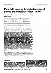
To use the representation in Claim 4 for computation, the first step is compute sets β ( Ci ( xi ) ) for each component i and for each value of each component. If there are N components, then there are N ⋅ G sets. Given the basis of an increasing filters, these sets are computed and stored. One also computes and stores the values of the filter at each basis element. Given a value x = ( x1 , K , x N ) , the first step is to retrieve N sets β ( Ci ( xi ) ) . Step two is to form the intersection of these N sets. The last step is to choose the maximum filter value among the basis elements in the intersection. To facilitate these steps, we label the basis elements with natural numbers in an increasing manner: B = {b1 , K , b T } such that i < j implies Ψ (b i ) ≤ Ψ (b j ) . Each label now represents a position in a bit vector. The set β ( Ci ( xi ) ) is represented by a length T bit vector where position j has value ‘1’ if b j ∈ β ( Ci ( xi ) ) and ‘0’ otherwise. We also maintain a lookup table (LUT) V that maps indices to filter values: V [ j ] = Ψ (b j ) . Each component of value x = ( x1 , K , x N ) is used to look up a bit vector, which are “ANDed” together. The maximum nonzero position of the resulting bit vector is used to index into table V to produce the filter value Ψ ( x ) . Figure 5 illustrates this architecture.
Window Values
x1
X1[t1],...,X1[tG] bit vector LUT
x2
X2[t1],...,X2[tG] bit vector LUT
X1[x1]=11100....
X2[x2]=11110....
Interval number to value LUT
result=111...0
AND
output value
Determine position i of first zero bit
XN[xN]=111110.... xN
XN[t1],...,XN[tG] bit vector LUT
Figure 5. Architecture for increasing filters.
4. SUMMARY CMM unifies binary and gray-scale nonlinear image processing in the context of lattices while providing a filter representation amenable to fast, compact execution. We have motivated CMM and presented a new efficient architecture for increasing and non-increasing filters. The architecture allows nonlinear filters to be executed in a few deterministic steps. Memory requirements are proportional to basis size.
5. REFERENCES 1. 2. 3.
E. R. Dougherty and D. Sinha, “Computational mathematical morphology,” Signal Processing 38, pp. 21-29, 1994. E. R. Dougherty and D. Sinha, “Computational gray-scale mathematical morphology on lattices (a comparator-based image algebra) Part I: Architecture,” Real Time Imaging 1, pp. 69-85, 1995. J. C. Handley, “Bit-vector architecture for computational mathematical morphology,” submitted, 2000.