Area*Time Optimized Hogenauer Channelizer Design Using FPL Devices 1
1
Uwe Meyer-Bäse , Suhasini Rao , Javier Ramírez2, and Antonio García2 1 Department of Electrical and Computer Engineering FAMU-FSU College of Engineering, Florida State University, USA {umb,rsuhas}@eng.fsu.edu 2 Department of Electronics and Computer Technology University of Granada, Spain
[email protected],
[email protected]
Abstract. Field-programmable logic devices (FPLDs) are on the verge of revolutionizing the digital signal processing (DSP) industry as programmable DSP microprocessor did nearly two decades ago. Historically, FPLDs were considered to be only a rapid prototyping and low-volume production technology. FPLDs are now attempting to move into the mainstream DSP as their density and performance envelope have steadily improved. While evidence now supports the claim that FPLDs can accelerate selected low-end DSP applications, the technology remains limited in its ability to realize high-end DSP solutions. This is primarily due to systemic weaknesses in FPLD-facilitated arithmetic processing. It will be shown that in such cases, a modified carry save adder (MCSA) arithmetic can become an enabling technology for realizing embedded high-end FPLD-centric DSP solutions. This thesis is developed in the context of a demonstrated MCSA/FPLD synergy and the application of the new technology to communication signal processing. Design synthesis results for Xilinx and Altera FPLDs are provided and show 22-164% speed improvement compared to 2C designs and require lower costs (A*T) in most study cases.
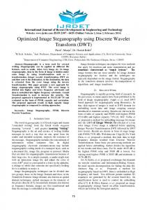
1 Introduction Compared to a cascaded collection of multirate FIRs, a Hogenauer [1] channelizer design (sometimes called, a cascade integrator comb (CIC) filter) can potentially run at a high input data rate and be of lower complexity. CIC filters are popular communication “building blocks” and are available as two’s complement arithmetic designs as Xilinx IP block [2] and as a COST IC by Harris/Intersil as HSP43220 [3]. A typical communication configuration for the use as a high decimation rate filter is shown in Fig. 1. The Hogenauer channelizer is well understood but, unlike their simple FIR counterparts, represents a significant design challenge because CIC filters require that
J. Becker, M. Platzner, S. Vernalde (Eds.): FPL 2004, LNCS 3203, pp. 384–393, 2004. © Springer-Verlag Berlin Heidelberg 2004
Area*Time Optimized Hogenauer Channelizer Design Using FPL Devices
385
Fig. 1. The Harris/Intersil HSP43320 Hogenauer decimating filter used in IF conversion.
all arithmetic, which can often exceed 66-bits word-widths, be exact. Large arithmetic word-widths immediately create a barrier to (non-pipelined) implementation which are generally relegated to low-precision applications (e.g., 8-bits). The design of such a filter using traditional methods and an ASIC/FPLD would be compromised due to the bandwidth and latency problems associated with high precision arithmetic. Our previous attempt [4,5] to solve this design problem involved the use of the residue number system (RNS) arithmetic. Although the RNS implementation improved the speed of the design, the overall cost measured as a product of area and time (area*time) was not favorable. We designed for instance a 3-stage CIC decimator using 26 bits. The 2C design cost metric was 343 LCs/49.3 MHz = 6.9, while the RNS metric was 559 LCs/76.3 MHz = 7.3. In addition the RNS design had benefited from the following two assumptions: − A second pole at ω=π was introduced to improve the speed of the modulo adders. − The output conversion from RNS arithmetic to two’s complement was not included in the area calculation of the design, while the first assumption may be valid due to the mandatory anti-aliasing filter in front of the CIC, the second assumption is only valid if the next processing step is also done in RNS. If the CIC filter is used as an embedded filter application within a two’s complement arithmetic system, input and output conversion need to be included in the cost (i.e. area*time product) of the design. A carry save adder (CSA) concept, however, provides a potential solution to this dilemma because CSA does not only provide essential speed improvement, via the absence of any carry propagation in the CSA design and the area penalty for CSA systems is less when compared with the RNS system, yielding an overall better cost measured by the area*time product.
386
U. Meyer-Bäse et al.
2 Hogenauer CIC Filter Theory A CIC filter devised by Hogenauer [1] is a multiplier free structure. The principal blocks of a CIC filter are an integrator and a comb or a differentiator with a rate changer in between. The transfer function of a CIC decimation filter with S stages is given by,
1 − z − RD H ( z ) = H I ( z ) H C ( z ) = −1 1− z
S
(1)
where D is the number of delays in the comb section and R is the down-sampling factor. From the above equation it can be seen that even though the integrators by themselves have an infinite impulse response, a CIC filter as a whole is equivalent to “S” moving average FIR filters. Figure 2 shows the step response of a single stage CIC filter without the rate changer. It can be seen that although the response of the integrator is infinity and shows overflow, but the final output y[n] is as expected due to the comb. Hence the filter's response is a moving average defined over D contiguous sample values. Such a moving average is a very simple form of lowpass filter.
Fig. 2. Step response of the first order Hogenauer filter without decimation.
Due to the presence of integrators and differentiators, register growth is a very important factor. In order to insure that no data is lost due to register overflow, the total internal word-width is calculated using the formula,
Bintern = Binput + S × log 2 ( RD) Bintern = Binput + Bgrowth
(2)
Thus the adder in the CIC filter design is crucial as it has to perform exact arithmetic with this word width at all levels so that no run-time overflow occurs at the output.
Area*Time Optimized Hogenauer Channelizer Design Using FPL Devices
387
2.1 Hogenauer Filter Design Using Carry Save Adders Carry Save adders (CSA) are popular in array multipliers due to the reduced latency provided with equivalent or superior speed performance. We have employed three different adder designs for the 5-stage, 16 bit input CIC filter design with a rate change factor of 1000 available as commercially IC from Harris/Intersil HSP43220. Each of these designs is synthesized for Xilinx’s and Altera’s FPLD and the results are tabulated. The CIC filter with two’s complement adder uses the least number of logic cells but with the increase in the number of stages and the number of input bits, the adder becomes very slow due to carry ripple. Several techniques for multiple operand addition that attempts to lower the carry propagation penalty have been proposed and implemented [6]. Among these, the CSAs are the fastest since there is no carry propagation until the last stage, while in the other stages a partial sum and a sequence of carries are generated separately. A CSA is nothing but a parallel counter th employing parity function, i.e., the k significant output bit is the parity function of k
one-bit 2 tuples in the vector [7,8]. We have incorporated these adders only in the integrator section in our design for study purpose however we have used two’s complement addition in the comb section. Due to the presence of the feedback in the integrator, the parallel counter design grows bigger with the number of stages in the CIC design. The first stage has a (3,2) CSA, the second stage has a (5,3) CSA and the third and the consecutive stages will have (6,3) CSAs as shown in the CIC structure in Fig. 3.
Fig. 3. Cascaded integrator comb filter using carry save adders.
Thus, with increase in the number of stages, the performance of this adder deteriorated using more silicon resource and decreased speed of computation. This drawback was overcome by the use of “Modified CSA” (MCSA) which is obtained by combining multiple (3,2)CSAs in a so-called Wallace tree [6]. In this tree, the number of operands is reduced by a factor of 2/3 at each level. Putting different, the number of operands in level (k+1) can be at most Nk3/2. Starting with the level 1 with one (3,2) CSA it follows that the maximum number of operands at level 2 is 9/2=4. The resulting sequence is therefore 3,4,6,9,13,19,28 etc. For the CIC design 2 levels of CSA are sufficient. Fig. 4 shows the resulting MCSA structure.
388
U. Meyer-Bäse et al.
Fig. 4. Cascaded integrator comb filter using modified carry save adders.
In general, input and the output bit width of a CIC filter are in the same range. Hence two different methods are employed in order to make the input and output word-width the same, pruning in the final stage and by pruning some LSBs at the previous stages. 2.2 Hogenauer’s Pruning Theory for Two’s Complement The quantization introduced through pruning in the final stage is very large when compared with the quantization introduced in the output by pruning some LSBs at the previous stages. If σ T , 2 S +1 is the quantization noise introduced through pruning in the output, Hogenauer suggested to set it equal to the sum of the (truncation) noise 2
σ T2,k introduced by all previous sections. For a CIC filter with S integrator and S comb sections, it follows that, 2S
2S
k =1
k =1
∑ σ T2,k = ∑ σ k2 Pk2 ≤ σ T2,2 S +1 1 2 σ T , 2 S +1 2S Pk2 = ∑ (hk [n]) 2 k = 1,2,...,2 S
σ 2 T ,k =
(3) (4) (5)
S
where
Pk2 is the power gain from stage k to the output. Compute next the number of
bits Bk which should be pruned by,
6 Bk = 0.5 log 2 Pk− 2 × × σ T2, 2 S +1 N 1 1 2( B −B + B ) σ T2,k k = 2 S +1 = 2 2 Bk = 2 in out growth 12 12
(6)
Area*Time Optimized Hogenauer Channelizer Design Using FPL Devices
The power gain
389
Pk2 for k=S,S+1,....2S for the comb sections can be computed using
the binomial coefficient,
H k ( z) =
2 S +1− K
2 S + 1 − k − kRD z n
∑ (−1) n =0
n
(7)
k = S , S + 1,...2 S .
2.3 CSA Pruning Technique From Figures 3 and 4 it can be seen that the CSA and MCSA designs introduce more noise sources than the original two’s complement design. More precisely, the MCSA introduces one additional noise source in all integrator sections, i.e., a total of S additional noise sources. The CSA configuration has one additional noise source in the first integrator, while all other CSA integrator sections have two additional noise sources, or a total of (2S-1) additional noise sources. We can take care of this additional noise source by adjusting (4) in Hogenauer’s pruning equations. There seemed to be two viable approaches that remove the degradation through the additional noise sources. In the error distribution technique we distribute the additional S or (2S-1) noise sources for MCSA and CSA, respectively, over all stages, including the comb sections, i.e., we replace (4) with
σ
2
T ,k
=
1 2 σ T , 2 S +1 for MCSA 3S 1 σ 2 T , 2 S +1 for CSA 4S − 1
for k = 1,...,2S
(8)
In the second approach (the direct quantization noise adjustment), we reduce the extra noise in each stage by scaling all noise sources to the allocated noise margin for that stage. We would then replace (4) by
σ 2 T ,k
1 1 2 σ T , 2 S +1 for CSA k = 1 and MCSA k = 1,..., S = 2 2S 1 1 2 σ T , 2 S +1 for CSA with k = 2,..., S 3 2S
(9)
The comb section will be unchanged in this case. The cic.exe program from [9] was modified in order to compute the modified bit width for the CSA and MCSA designs using the above two methods. The program provides the maximum bit growth as well as the number of bits to be retained at each stage for the CIC design using pruning. For the 5-stage design with 16 bit input and output bit width and a rate change factor of 1024, Bmax is 66. The result of executing
390
U. Meyer-Bäse et al.
this program is tabulated below in Table 1. We note that one more guard bit in the integrator section and comb sections is sufficient to implement the (M)CSA design with the same quantization error as the two’s complement design. Comparing the error distribution techniques with the direct method we see that error distributions yield larger required bit width in the comb sections and therefore we used the direct quantization method (shown bold in Table 1) without error distribution for our designs. Table 1. Carry save adder pruning data.
Type 2C CSA MCSA CSA MCSA
Distribute Error No Yes Yes No No
Integrator sections
Comb sections
1
2
3
4
5
1
2
3
4
5
63 63 63 63 63
53 53 53 53 53
43 44 44 44 44
35 35 35 35 35
26 27 27 27 27
22 23 22 22 22
21 22 22 21 21
20 21 21 20 20
19 20 20 19 19
19 19 19 19 19
3 Synthesis Results Circuits for 5-stage CIC filters using 2C, MCSA, and CSA arithmetic in full bit width and pruning technique have been developed using generic VHDL coding. Circuits have then been synthesized from their VHDL descriptions and optimized for speed and area using synthesis tools from Altera and Xilinx. To have an first impression on the possible performance gain we have compiled the data for single adders using CSA, MCSA, and 2C which are graphically interpreted in Fig. 3. We note the speed improvement especially for large bit-width adders of the CSA and MCSA when compared with the two’s complement adder (2C).
Fig. 5. Result of synthesis of the adder designs on Xilinx’s FPLD.
Area*Time Optimized Hogenauer Channelizer Design Using FPL Devices
391
3.1 CIC Xilinx Synthesis Results The synthesis results for the Xilinx Virtex Device XCV300e-pq240-6 compiled with the ISE web-pack tool set shows similar results as with Altera devices and software. Because the Xilinx logic cells have two 4-input and one 3-input tables, the design area used is the equivalent number of gates from the Xilinx “Mapping Report File.” To have reliable timing data we use the “Post Place&Route Static Timing Report” rather than the map time estimations. As mentioned before, when designed using a two’s complement adder, the number of inputs to each stage remains the same regardless of the number of stages. Whereas, when designed using a CSA, the first stage has (3,2) CSA, the next stage uses (5,3) CSA and the third (6,3) CSA and for further stages it remains the same. When used with MCSA, the first stage has (3,2) CSA, the second stage uses (4,2) MCSA and this remains the same for all the further stages. Table 2. Synthesis data of 5-stage CIC filter on Xilinx’s FPLD.
The design field indicates the CIC filter design with the best synthesis option using CSA (with parallel counter logic), MCSA (as in Modified CSA) and CIC (using two’s complement adder). We notice the speed improvement both for the CSA as well the MCSA design with and without pruning. The cost measured by the time*area product is improved only for the MCSA design without pruning. Table 2 also includes the required minimum sampling rate reduction between the integrator and comb section as measured by the quotient of integrator clock and comb clock, i.e., ceil(clkI/clkC). For all designs the required minimum sampling rate reduction is 3, which is most likely well below the usual high decimation rate factor CIC are used in communication systems.
392
U. Meyer-Bäse et al.
3.2 CIC Altera Synthesis Results The synthesis results of 5-stage CIC filters using the above mentioned means of arithmetic is shown in Table 3. The designs are synthesized for Altera’s FPLD device EPF10K130EQC240-1. The designs include both the pruning methods mentioned above. The best performance of each of these designs for the different speed and style options is tabulated. LCs gives the number of logic cells used, Fmax is the Registered Performance, and Cost = LCs/Fmax(10-6) gives the cost of the design. From the above table it can be seen that pruning at each stage decreases the total LCs used and thereby improves the speed. CIC filter design using two’s complement adder uses minimal resource but at the same time the speed is the least compared to other designs. Though MCSA uses twice the number of LCs, the speed is three times faster than the design using two’s complement adder, thereby making the design more cost effective. Table 3. Synthesis data of 5-stage CIC filter on Altera’s FPLD.
Table 3 shows only the best results regarding cost metric area*time. For a complete listing including the optimum synthesis results for maximum speed optimization we reference to [10].
4 Conclusions The Hogenauer’s [1] design of two’s complement cascade integrator comb filter was extended to carry save adder design. Using a digital signal processing scheme with CSA provides fast filter building blocks. These filters are of low complexity and are multiplier free, so that fast compact decimators and interpolators can be implemented without the high cost of RNS implementation as previously proposed [4,5]. The quantization error analysis for CSA shows that no more than one additional guard bit precision is needed when compared with Hogenauers pruning for two’s complement. Synthesis results for a typical design example used in the Harris/Intersil HSP43220 have been compiled and show an improvement in speed from 84% to 164% and up to 31% costs improvements for Altera FPLDs. Improvements in speed from 22% to
Area*Time Optimized Hogenauer Channelizer Design Using FPL Devices
393
106% and up to 41% for costs metric (A*T) for Xilinx Virtex FPLDs when compared with the conventional two’s complement design are reported.
Acknowledgements. The authors would like to thank Altera and Xilinx for their support under the University programs. A. García was supported by the Ministerio de Ciencia y Tecnología (MCyT, Spain) under project TIC2002-02227.
References 1.
E.B. Hogenauer, “An Economical Class of Digital Filters for Decimation and Interpolation”. IEEE Transactions Acoustics, Speech and Signal Processing, Vol. 29(2) (1981) 155-162 2. www.xilinx.com/ipcenter 3. http://www.intersil.com/design/parametric/deviceinfo.asp?pn=HSP43220 4. U. Meyer-Baese, A. Garcia, F. Taylor, “Implementation of a Communications Channelizer using FPLDs and RNS Arithmetic”, Journal of VLSI Signal Processing, Vol. 28, (2001) 115–128 5. García, A., Meyer-Bäse, U., Taylor, F. J., “Pipelined Hogenauer CIC Filters Using FieldProgrammable Logic and Residue Number System,” IEEE International Conference on Acoustics, Speech and Signal Processing, Seattle, WA, Vol. 5, (1998) 3085-3088 6. I. Koren, “Computer Arithmetic Algorithms”, Prentice Hall, Eaglewood Cliffs, New Jersey (1993) 7. M. Mehta, V. Parmar, E. Swartzlander Jr, “High-Speed Multiplier Design using MultiInput Counter and Compressor Circuits”, in Proceedings of the 10th International Symposium Computer Arithmetic, (1991) 43-50 8. Y. Leblebici, H. Ozdemir, A. Kepkep, U. Cilingiroglu, “A compact High-Speed (31,5) Parallel Counter Circuit Based on Capacitive Threshold-Logic Gates”, IEEE Journal of Solid-State Circuits, Vol. 31(8), (1996) 1177-1183 9. U. Meyer-Baese, “Digital Signal Processing with Field Programmable Gate Arrays”, Springer-Verlag, Heidelberg (2001) 10. S. Rao, “Multirate Filter Design on Field Programmable Gate Arrays,” Master’s Thesis, Florida State University, Tallahassee (2003)