Aug 19, 2015 - abroad, or from public or private research centers. L'archive ouverte ... particular, targets secure-by-design embedded systems.
Assisting the Design of Secured Applications for Embedded Systems Gabriel Pedroza
To cite this version: Gabriel Pedroza. Assisting the Design of Secured Applications for Embedded Systems. Computer Aided Engineering. T´el´ecom ParisTech, 2013. English. .
HAL Id: tel-01185312 https://pastel.archives-ouvertes.fr/tel-01185312 Submitted on 19 Aug 2015
HAL is a multi-disciplinary open access archive for the deposit and dissemination of scientific research documents, whether they are published or not. The documents may come from teaching and research institutions in France or abroad, or from public or private research centers.
L’archive ouverte pluridisciplinaire HAL, est destin´ee au d´epˆot et `a la diffusion de documents scientifiques de niveau recherche, publi´es ou non, ´emanant des ´etablissements d’enseignement et de recherche fran¸cais ou ´etrangers, des laboratoires publics ou priv´es.
2013-ENST-001
EDITE - ED 130
Doctorat ParisTech THÈSE pour obtenir le grade de docteur délivré par
TELECOM ParisTech Spécialité: Télécommunications et Electronique présentée et soutenue publiquement par Juan Gabriel PEDROZA BERNAL le 10 janvier 2013
Conception Assistée des Logiciels Sécurisés pour les Systèmes Embarqués Jury Prof. Jean-Louis LANET Prof. Frédéric CUPPENS Dr. Luca COMPAGNA Prof. Mireille BLAY-FORNARINO Dr. Ludovic APVRILLE Prof. Renaud PACALET
Université de Limoges Télécom Bretagne SAP Research Center S.A. Université de Nice (UNSA) Télécom ParisTech Télécom ParisTech
TELECOM ParisTech école de l’Institut Mines-Télécom
Rapporteur Rapporteur Examinateur Examinateur Directeur de Thèse Co-Directeur de Thèse
iii
To my loved ones To my mentors and sponsors
Acknowledgements I would like to express my thankfulness to the persons that helped me to obtain my Ph.D. Initially, to my supervisors Renaud Pacalet and Ludovic Apvrille who led me during almost four years. Secondly, to the jury members, in particular to Jean-Louis Lanet and Frédéric Cuppens, the reviewers of my thesis. A huge thanks for the fruitful discussions with colleagues, friends, and researchers from the System-on-Chip laboratory and Eurecom. To keep it short, I will avoid listing all them but they already occupy a place in my memory. An important part of my work was conducted in the scope of the EVITA project. It was certainly an outstanding opportunity and an amazing experience for collaborating and learning. I sincerely express to all EVITA partners my gratitude. Special thanks to Hendrik Schweppe, Yves Roudier, Hagen Platzdasch, Hervé Seudié, Wolfgang Wiewesiek, Franz Pirklbauer, Timo Gendrullis, Sigrid Gürgens, and Andreas Fuchs. The Eurecom staff kindly hosted me during these years and I want to say thanks a lot for the permanent and awesome support. I am truly lucky to have met all those persons. Last but not least, I would like to recognize the funds and support received via the following institutions: • Government of France • Institut de Mines Télécom/Télécom ParisTech • European Commission FP7 • National Council for Science and Technology of México (CONACyT) Their support was essential to accomplish this objective.
iv
v
Abstract The Intelligent Transport Systems (ITS) arose several years ago pursuing the introduction of smarter in-vehicle systems in order to assist drivers and make roads safer. From the ITS perspective, vehicles are seen as mobile communicating hubs inside a large, diversified, complex, and easily accessible network. Consequently, the deployment and operation of on-board architectures shall face a wide variety of threats that may endanger vehicle safety and human being lives. A vast majority of distributed embedded systems is also concerned by security risks. The fact that the applications may result poorly protected is partially due to methodological lacks in the engineering development process. More specifically, consider security as an after thought is not as effective as its early introduction during system conception stages. Since formal methodologies have been successfully applied to ensure properties of concurrent systems, we believe that their appropriate integration into the engineering development process may help to ensure security of applications. Methodologies targeting formal verification may lack support to certain phases of the development process. Particularly, system modeling frameworks may be complex-to-use or not address security at all. Along with that, testing is not usually addressed by verification methodologies since formal verification and testing are considered as exclusive stages. Nevertheless, we believe that platform testing can be applied to ensure that properties formally verified in a model are truly endowed to the real system. Our contribution is made in the scope of a model-driven based methodology that, in particular, targets secure-by-design embedded systems. The methodology is an iterative process pursuing coverage of several engineering development phases and that relies upon existing security analysis techniques. Still in evolution, the methodology is mainly defined via a high level SysML profile named Avatar. The contribution specifically consists on extending Avatar so as to model security concerns and in formally defining a model transformation towards a verification framework. This contribution allows to conduct proofs on authenticity and confidentiality and also provides a basis to later support proofs on other security properties. We illustrate how an automotive cryptographic protocol is partially secured by applying several methodology stages like System Analysis, Threats Analysis, Requirements Structuring, Properties Modeling, System Design, Formal Verification, and Coverage Assessment. In addition, it is described how Security Testing was conducted on an embedded prototype platform within the scope of an automotive project and relying upon state of the art techniques.
vi
vii
Contents 1 Introduction 1.1 Context . . . . . . . . . . . . . . 1.2 Problematic . . . . . . . . . . . . 1.3 Contributions . . . . . . . . . . . 1.3.1 Objective . . . . . . . . . 1.3.2 Thesis Approach Synopsis 1.4 Outline . . . . . . . . . . . . . .
. . . . . .
. . . . . .
. . . . . .
. . . . . .
. . . . . .
. . . . . .
. . . . . .
2 Security and Vehicular Applications 2.1 Vehicular Applications Evolution and Security 2.1.1 80’s Decade Developments . . . . . . . 2.1.2 90’s Decade Developments . . . . . . . 2.1.3 2000’s Decade Developments . . . . . 2.1.4 From 2010 Up to Now Developments . 2.2 Current Vehicles Architecture . . . . . . . . . 2.3 Uncovered Security Aspects . . . . . . . . . . 2.3.1 Critical Security Aspects . . . . . . . . 2.3.2 Known Attacks and Potential Impact . 2.3.3 Hypothetical Automotive Attack . . . 2.4 Conclusions . . . . . . . . . . . . . . . . . . .
. . . . . . . . . . . . . . . . .
. . . . . . . . . . . . . . . . .
. . . . . . . . . . . . . . . . .
. . . . . . . . . . . . . . . . .
3 Methodologies for Embedded Systems Verification 3.1 Verification Methodologies Survey . . . . . . . . . . . 3.1.1 Generic Formal Theories . . . . . . . . . . . . 3.1.2 Generic Formal Based Tools . . . . . . . . . . 3.1.3 Formal Security Oriented Methodologies . . . 3.1.4 Cryptographic Protocol Oriented Approaches 3.1.5 Model Driven Engineering Environments . . . 3.1.6 High Level Non-MDE Environments . . . . . 3.1.7 Certification Oriented Approaches . . . . . . 3.2 Qualitative Evaluation of Verification Approaches . . 3.2.1 Features by Category . . . . . . . . . . . . . . 3.2.2 Pros and Cons of Verification Methodologies . 3.2.3 Properties Support and Framework Usability 3.3 Summary and Conclusions . . . . . . . . . . . . . . .
. . . . . . . . . . . . . . . . . . . . . . . . . . . . . .
. . . . . . . . . . . . . . . . . . . . . . . . . . . . . .
. . . . . . . . . . . . . . . . . . . . . . . . . . . . . .
. . . . . . . . . . . . . . . . . . . . . . . . . . . . . .
. . . . . . . . . . . . . . . . . . . . . . . . . . . . . .
. . . . . . . . . . . . . . . . . . . . . . . . . . . . . .
. . . . . . . . . . . . . . . . . . . . . . . . . . . . . .
. . . . . . . . . . . . . . . . . . . . . . . . . . . . . .
. . . . . . . . . . . . . . . . . . . . . . . . . . . . . .
. . . . . . . . . . . . . . . . . . . . . . . . . . . . . .
. . . . . . . . . . . . . . . . . . . . . . . . . . . . . .
. . . . . . . . . . . . . . . . . . . . . . . . . . . . . .
. . . . . .
1 1 2 3 3 4 4
. . . . . . . . . . .
5 5 5 6 7 9 11 14 14 16 18 20
. . . . . . . . . . . . .
23 25 25 26 28 30 31 34 36 37 38 39 42 45
viii 4 Proposed Methodology for Verifying Critical 4.1 Contributions and Methodology Overview . . 4.2 Methodology Description . . . . . . . . . . . . 4.2.1 Threats Analysis . . . . . . . . . . . . 4.2.2 System Analysis . . . . . . . . . . . . 4.2.3 System Design . . . . . . . . . . . . . 4.2.4 Requirements Structuring . . . . . . . 4.2.5 Properties Modeling . . . . . . . . . . 4.2.6 Formalization and Verification . . . . . 4.2.7 Coverage Assessment . . . . . . . . . . 4.2.8 Code Generation and Adaptation . . . 4.2.9 Platform Tests . . . . . . . . . . . . . 4.3 Conclusions . . . . . . . . . . . . . . . . . . .
CONTENTS Embedded Systems . . . . . . . . . . . . . . . . . . . . . . . . . . . . . . . . . . . . . . . . . . . . . . . . . . . . . . . . . . . . . . . . . . . . . . . . . . . . . . . . . . . . . . . . . . . . . . . . . . . . . . . . . . . . . . . . . . . . . . . . . . . . . . . . . . . . . . . . . . . . . . . . . . . . . . . . . . . .
. . . . . . . . . . . .
. . . . . . . . . . . .
. . . . . . . . . . . .
. . . . . . . . . . . .
49 49 53 53 56 58 61 66 69 71 73 76 82
5 Assisted Design with Avatar 5.1 The Avatar Design Framework: An Overview . . . . . . . . . 5.1.1 Avatar Design Metamodel . . . . . . . . . . . . . . . . 5.1.1.1 Block Metamodel Components . . . . . . . . 5.1.1.2 SMD Metamodel Components . . . . . . . . 5.1.2 Avatar Design Framework Implementation . . . . . . . 5.2 Extending Avatar Design Profile . . . . . . . . . . . . . . . . 5.2.1 Avatar Design Limitations . . . . . . . . . . . . . . . . 5.2.2 Avatar Extensions: The Avatar Security Environment 5.3 Attaching a Formal Semantics to AvatarSE . . . . . . . . . . 5.3.1 Avatar & AvatarSE Formal Descriptions . . . . . . . . 5.3.1.1 Avatar Formal Description . . . . . . . . . . 5.3.1.2 AvatarSE Formal Description . . . . . . . . . 5.3.2 AvatarSE-to-ProVerif Transformation . . . . . . . . . . 5.3.3 Example of Transformation . . . . . . . . . . . . . . . 5.4 Approach Limitations and Conclusions . . . . . . . . . . . . . 5.4.1 Approach Limitations . . . . . . . . . . . . . . . . . . 5.4.2 Conclusions . . . . . . . . . . . . . . . . . . . . . . . .
. . . . . . . . . . . . . . . . .
. . . . . . . . . . . . . . . . .
. . . . . . . . . . . . . . . . .
. . . . . . . . . . . . . . . . .
. . . . . . . . . . . . . . . . .
. . . . . . . . . . . . . . . . .
. . . . . . . . . . . . . . . . .
. . . . . . . . . . . . . . . . .
83 84 84 86 88 91 94 95 97 101 102 103 107 111 117 119 121 122
6 Case Study: Securing and Testing EVITA Architecture 6.1 Securing EVITA Symmetric Keying Protocol . . . . . . . 6.1.1 Initial System Analysis . . . . . . . . . . . . . . . . 6.1.2 Threats and Requirements Analyses . . . . . . . . 6.1.3 Design and Verification . . . . . . . . . . . . . . . 6.1.4 Attack Coverage Assessment . . . . . . . . . . . . 6.1.5 Conclusions: Case Study I . . . . . . . . . . . . . . 6.2 EVITA HSM Driver Tests . . . . . . . . . . . . . . . . . . 6.2.1 HSM Driver Context . . . . . . . . . . . . . . . . . 6.2.2 Driver Test Method . . . . . . . . . . . . . . . . . 6.2.3 Driver Testing Environment . . . . . . . . . . . . . 6.2.4 Results and Discussion . . . . . . . . . . . . . . . . 6.2.5 Conclusions: Case Study II . . . . . . . . . . . . .
. . . . . . . . . . . .
. . . . . . . . . . . .
. . . . . . . . . . . .
. . . . . . . . . . . .
. . . . . . . . . . . .
. . . . . . . . . . . .
. . . . . . . . . . . .
. . . . . . . . . . . .
125 126 126 129 133 135 138 140 140 141 142 144 145
. . . . . . . . . . . .
. . . . . . . . . . . .
ix 7 Conclusions and Perspectives 7.1 Initial Findings . . . . . . . . . . . . . . . . . . . . . . . . . . . . . . . . . . 7.2 Contributions and Conclusions . . . . . . . . . . . . . . . . . . . . . . . . . 7.3 Discussion: Shortcomings and Perspectives . . . . . . . . . . . . . . . . . . .
147 147 148 150
A Underlying Formal Backend 153 A.1 ProVerif . . . . . . . . . . . . . . . . . . . . . . . . . . . . . . . . . . . . . . 153 Bibliography
173
x
CONTENTS
List of abbreviations ACC ACP API ASIC AvatarRD AvatarSE CAM CAN CASE CC CCU CSP CTL TCTL DoS DSRC EAL EBCM ECU EMI EVITA FPGA FIFO FR FSR FSP FP GPS HMAC HMI HOL HSM IT ITS LIN LLD LTL LTS MAC MAC MDE MOST NFP NFR NFSR NFSP
Adaptive Cruise Control Algebra of Communicating Processes Application Programming Interface Application-Specific Integrated Circuit Avatar Requirements Diagram Avatar Security Environment Cooperative Awareness Message Controller Area Network Computer Aided Software Engineering Common Criteria Communication Control Unit Communicating Sequential Processes Computational Tree Logic Timed CTL Denial of Service Dedicated Short-Range Communications Evaluation Assurance Level Electronic Brake Control Module Electronic Control Unit Electromagnetic Interference E-safety Vehicle Intrusion Protected Applications Field Programmable Gate Array First In/First Out Functional Requirement Functional Security Requirement Functional Security Property Functional Property Global Positioning System Hash-Based MAC Human-Machine Interface High Order Logic Hardware Security Module Information Technology Intelligent Transport Systems Local Interconnect Network Low Level Driver Linear Temporal Logic Labeled Transition System Message Authentication Code Media Access Control Model Driven Engineering Multimedia Oriented Systems Transport Non-Functional Property Non-Functional Requirement Non-Functional Security Requirement Non-Functional Security Property
xi OCL OEM OS PKI RF RSU SAM SeMF SMD SMV SPI ST SysML TCB TEPE ToE TPM TTA UML UMTS UTC V2I V2V V2X VANET
Object Constraint Language Original Equipment Manufacturer Operating System Public-Key Infrastructure Radio Frequency Road-Side Unit Software Architecture Modeling Security Modeling Framework State Machine Diagram Symbolic Model Verifier Serial Peripheral Interface Security Target Systems Modeling Language Trusting Computing Base Temporal Property Expression Language Target of Evaluation Trusted Platform Module Time Triggered Architecture Unified Modeling Language Universal Mobile Transmission System Coordinated Universal Time Vehicle to Infrastructure Vehicle to Vehicle Vehicle to Vehicle (V2V) and/or Vehicle to Infrastructure (V2I) Vehicular Ad-Hoc Network
xii
CONTENTS .
1
Chapter 1
Introduction 1.1
Context
The Intelligent Transport Systems (ITS) arose several years ago impelling the design of new applications in the automotive industry. The ITS paradigm envisages a wide network of mobile vehicles and fixed architecture to exchange information so as to make roads more coordinated. The architecture not only for in-car exchanges but also for vehicle and road side architecture communications should still be developed. The ITS network pursues several objectives many of which are in the scope of driver safety: 1. Assist driver/car in emergency maneuvers, e.g., to reduce impact in collisions. 2. Broadcast warning messages, e.g., drivers are warned of road dangers ahead. 3. Provide toll services, e.g., automatic emergency call after a crash. 4. Lead to interactive road side architecture, e.g., radars enforce speed limits. 5. Improve traffic flow, e.g., driver is assisted in seeking for alternative routes. Several challenges should be faced before ITS becomes a viable alternative. For instance, the creation of new standards is necessary to regulate/harmonize implementations. Harmonization is a mean to achieve interoperable technology across countries. Standardization may demand that a wide range of topics be addressed: from technical aspects up to legal ones. To ensure interoperability, agreements between involved countries seem mandatory. Moreover, vehicles should be equipped with reliable and secure ITS implementations. Thus, car makers, service providers, and developers are highly concerned with embedded systems dependability. ITS deployment strongly depends upon the level of trustiness achieved in automotive applications. Designers have started to consider security from the very first design stages by imposing stringent requirements. It is generally accepted that for achieving security and technical objectives, hardware and software threats should be identified, analyzed, and prevented. To do so, external communication (V2X) as well as internal on-board architecture need to be secured. Indeed, exchanges over public communication channels are typical targets of attackers. Hostile actions may threaten not only wireless vehicle exchanges (V2X communication) but also wired links, i.e., exposed buses and ports inside the vehicle (in-car communication). As referred in several works, current automotive embedded systems may
2
1. Introduction
be the target of a variety of attacks [121], [123], [181], [156], [46], [202], [47], [179], [25], [217], [29]. The technology and resources required to threaten vehicles are sophisticated but eventually accessible. It means that a skilled and motivated hostile party has chances of overtaking on-board systems and compromising vehicle operation. The impact of attacker actions may even endanger driver safety and human being lives [121], [123]. Also, the privacy of drivers may be compromised via vehicles tracking [25], [217]. Along with that, as recently occurred [47], poorly protected systems may lead to vehicles theft what damages owners’ economy. Improve in-car applications so as to better protect them against the hostile environment is imperative in order to achieve ITS objectives. The correct operation of safety critical applications like braking strongly depends upon trusted exchanges. Also, facilities that warn drivers must be trusted so as to properly enlarge driver’s view ahead. Introduced facilities may prevent casualties or reduce their impact, e.g., passengers injuries, car damages, thus improving vehicular safety [199], [212].
1.2
Problematic
Many distributed embedded systems are threatened by hazards similar to the ones in the automotive domain. To achieve a certain level of SW/HW applications protection, formal verification has been proposed and successfully used, see [102]. Thus, formal techniques may also help to improve ITS development [135], [50]. However, the adequate integration of formal techniques into the engineering development process needs to be thoroughly addressed. Several approaches applied for securing vehicle architectures are empirical and limited to undertake certain issues. In particular, some proposals only protect the system against specific attack cases, e.g., [89], [215], [124]. In others, the effectiveness of security countermeasures is not proved against any adversary, e.g., [114], [99], [140]. Securing applications only considering specific hazards may be ineffective with respect to real hostile environment [97]. Relying upon a local-view paradigm strengthens certain aspects of the engineering development process whereas other critical concerns may remain barely or not addressed at all. We believe that adopting a global-view may help to better identify methodological lacks that have led to poorly protected applications. Security of distributed embedded systems is a vast and highly complex problem. To our knowledge, there is neither master guide nor golden rule that provides security and ensures overall system protection. So far, we aim to improve certain methodological issues: 1. To some extent, several automotive applications are currently vulnerable to attacks. Those cases show that the engineering development process may produce poorly protected systems. Thus, the support provided to certain development phases should be improved. 2. Several system development approaches have mainly focused in functional aspects and security was rather an afterthought. Those approaches have resulted ineffective for achieving system protection. 3. An adequate framework for modeling complex embedded systems is crucial. Many frameworks are engineer-oriented but unfortunately informal. On the contrary, many methodologies that introduce formal techniques are too complex what compromises
3 their usability. Adequate integration of formal techniques into the engineering design process is an important task to be addressed. 4. A verification methodology capable of addressing the whole set of requirements of typical specifications is worth having. Verification methodologies usually focus on a certain kind of requirements. Nonetheless, development of critical embedded systems may demand evaluation of time, functional, and security features. 5. Many verification methodologies introducing formal techniques do not support automated proofs. Modeling and verifying formal models by hand may be complex, time consuming, and prone to error. In addition, a modeling framework should effectively consider constraints imposed by embedded in-car systems: • Real time constraints: Applications should act-react according to time constraints imposed by critical scenarios, e.g., car braking in a collision scenario. • Resource constraints: Embedded systems are constrained by limited hardware resources, e.g., by memory, CPU power, and/or bus capacity. • Complex heterogeneity: In-car infrastructure is quite heterogeneous and complex. A car embedded system is integrated by several kinds of HW and SW modules: processors, memories, software drivers, operating systems, user applications, security protocols, etc. • Complex communication: Exchanges in distributed embedded applications are supported by complex bus policies and protocols. Overall system operation strongly depends upon them.
1.3 1.3.1
Contributions Objective
Based upon identified issues, a methodology to conduct formal verification of concurrent embedded systems with respect to functional and non-functional requirements is targeted. Our main contribution is made in the scope of that methodology. Our approach adopts a global view of the engineering development process as a way to identify lacks in methodological support. Thus, the aspects to be particularly addressed are: a. Modeling of embedded systems (HW-SW): To ensure its usability, a modeling framework should ease integration of formal languages and be also adequate for analyzing features of embedded systems. b. Modeling of functional and non-functional requirements: Development of automotive embedded systems often demands verification of time, functional, and also security requirements. A framework suitable for those tasks is worth having. c. Representation of threats model required in security proofs: System features are proved against an attacker model. The effectiveness of achieved system protection strongly depends upon threats model accuracy.
4
1. Introduction d. Framework formalization and verification: In order to keep our approach engineer oriented, formal issues are not introduced at modeling level. Instead, formalization is made by model transformation and verification is carried out at backend level exploiting formal based tools. e. Assessment of attack protection: A stage that precises the extent of verification results is proposed. A post-verification analysis is introduced in order to show satisfied/unsatisfied requirements as well as respective covered attacks. f. Functional and non-functional tests: Code is automatically generated from verified models. However, handmade code may be integrated so as to execute the application inside a host platform. A stage is proposed to validate final implementation features.
1.3.2
Thesis Approach Synopsis
First, a set of uncovered security aspects in automotive embedded systems is precised. To do so, the development of in-car embedded applications in the last decades is exposed what shows how security has been addressed. Several aspects that have been barely or not covered at all are thus identified. Afterwards, the support offered by current verification methodologies to the engineering development process is analyzed. The objective is to identify/precise lacks that may impede effective protection of embedded systems. The analysis is conducted as follows. Several verification methodologies are reviewed, their main features exhibited, and the support provided to the engineering development phases evaluated. Since lacks are identified in several phases, an overall methodology is accordingly proposed. Methodology relies upon existing security analysis techniques. Thesis contribution is made in the scope of proposed methodology. Indeed, it introduces means pursuing both missing support and effective protection against attacks. The problematic aspects signaled in section 1.2 aim to be undertaken. In particular, the design framework is extended so as to model security concerns. This contribution endows the environment with a formal semantics and makes it adequate for proving security properties. The methodology is suitable for verification of embedded systems in general. Its applicability has been partially shown in an industrial automotive project [77]. Also, some results of this work have been published [159], [160].
1.4
Outline
This manuscript is structured as follows. In chapter 2 a state of the art of embedded automotive applications is exposed. Among others, the chapter shows several aspects that have impeded appropriate embedded systems protection. Chapter 3 evaluates the features offered by several verification methodologies and shows the lack of support to certain engineering development phases. Justifications to thesis contributions are precised in this chapter. The global methodology that aims to undertake identified issues is shown in chapter 4. Stages introducing a contribution are accordingly highlighted. A main contribution consists in introducing formal techniques without compromising modeling framework usability. Chapter 5 is dedicated to show it. To show approach applicability, the methodology is applied in an industrial automotive case study that is exposed in chapter 6. Since the methodology supports both safety and security analyses, two instances are respectively targeted. The conclusions and work perspectives are finally provided in chapter 7.
5
Chapter 2
Security and Vehicular Applications In this chapter we precise several aspects that may render vehicle applications not enough secured. To do so, a survey on vehicular applications evolution is first shown. This survey provides an explanation about why security became a trendy topic of research in the automotive domain. It shows the late introduction of security in applications development, and the initial efforts performed for securing. The main goal consists in assessing to which extent security protections may nowadays result ineffective. Afterwards, a typical mobile architecture is described what exhibits the complexity of current on-board in-car systems. Complexity of embedded architectures is a challenge for achieving security goals since it notably increases the difficulty of system analyses during development [120]. A reference automotive architecture is mostly taken from an European project that targeted security of distributed on-board applications [77]. Several threats in vehicular networks are summarized relying upon the reference architecture. More particularly, infrastructure weaknesses, threats, and potential impact are shown. The conclusions summarize our findings and justify the need for improving certain aspects in methodological support.
2.1 2.1.1
Vehicular Applications Evolution and Security 80’s Decade Developments
At early eighties, several proposals were published pursuing remote control of vehicles from a traffic center. For instance in [17], vehicles receive control signals via rail guides connected to Radio Frequency (RF) antennas. Several in-vehicle functions are directly programmed on microprocessors and many of those functions target vehicle safety. Indeed, speed control, collision avoidance, and emergency braking applications receive guideway inputs and react in consequence. Even if safety was stated among the general objectives, the main goal was traffic improvement by settling policies according to transport demand in real time. However, no security aspect is considered at all and the approach focused only on functional aspects. Focusing on functional concerns is a tendency observed in many efforts published during mid and late 80’s. Some standalone applications delivered as a vehicle add-on roughly addressed security. On the contrary, in many other instances security is not addressed at all. For example in [16], a technology for vehicle identification based upon RF is presented. The system pursued identification and location of vehicles with a fixed schedule, e.g., buses, trucks or even rail guided cars. It is recognized that communication between RF
6
2. Security and Vehicular Applications
readers and vehicle’s card may be perturbed by physical factors - like Electromagnetic Interference (EMI) [221]. However, it is claimed that the system can be applied in sensitive services like toll payment, even if no security analysis is conducted [16]. In late 80’s, in-vehicle systems conception evolves towards a more autonomous approach. Instead of envisaging a remote automated control of vehicles, driver’s role is kept whereas in-car applications only assist the driver. Since developing in-car applications became challenging and costly, the communication between vehicles and outside world should be first justified [220]. The in-car architecture evolved from being a set of standalone application-oriented controllers, to an internal network of processing units. As explained in [80], increasing the number and complexity of in-car applications would likely increase the number of transfers. Thus, a message in-car network is proposed as an efficient solution to avoid bottlenecks. The envisaged network is composed by a Master Station that provides global facilities and controls a two-wire bus to which Control Units are connected. Control Units are in charge of a wide range of dedicated devices, like sensors, display, wipers, lights, and also generic device arrays. A diagnostic Station is introduced for monitoring and storing overall bus exchanges and other critical device operations, e.g., in engine control unit. Such facility is intended to perform off-service vehicle diagnostics by wired connection. Among the benefits of this in-car network are easier installation and reconfiguration, and the ability for supporting more advanced subsystems [80]. Nonetheless, the approach does not address any security aspect and development objectives remained functional and safety oriented.
2.1.2
90’s Decade Developments
In early 90’s, technologies became more specialized leading to a growing complexity. Along with that, drawbacks and challenges of in-car networks are pointed out. As stated in [135], a failure in a complex inter-connected system may affect several components. Oppositely to previous standalone architectures, in-vehicle networks target reconfiguration and scalability what also increases complexity. Thus, even typical components with a very good record of failures became inter-dependent what impacted overall system reliability [135]. Consequently, other requirements than purely functional ones arose. In the work presented in [135], possible sources of failure are classified: Random Failures, due to physical misbehaviour or damage, Systematic Errors, due to wrong HW or SW designs, and Intermittent Failures, due to environmental conditions. To cope with those failures, redundancy in system components is proposed, e.g., double or triple processor architectures in charge of equivalent functions. Nevertheless, redundancy is not enough to cope with Systematic Errors, since they mainly depend upon faulty system specification or design [135]. Even if formal verification is mentioned as a mean to ensure correctness no formal analysis is conducted. A milestone for consolidation of in-vehicle networks was the development of communicating protocols. Several efforts were conducted to deploy not only in-car but also V2I and V2V communications. This tendency was greatly motivated by projects launched during late eighties like PROMETHEUS and DRIVE. Those projects mainly targeted traffic management and control. As mentioned in [66], roadside communication architecture mostly remained local. More intelligence and computing power were settled in on-board
7 systems. Rather than proposing new applications, many efforts were dedicated to deploy prototypes of proposed embedded systems, e.g., the one in [66]. Two domains integrating vehicle architectures are clearly identified: one for the in-car network (on-board) and the other for the envisaged overall network of vehicles and roadside architecture - also referred as vehicular or off-board network. Nodes within in-vehicle network are modular SW/HW components named Electronic Control Unit (ECU)s. They support local and distributed vehicle applications. ECUs are interconnected via a variety of buses and links. It is observed that industry and academy progressively changed the objectives of both in-car and off-board networks. Rather than an automated control of traffic, ameliorate vehicular safety became a major concern [15]. A way to improve vehicular safety is to virtually increase driver vision ahead, e.g., by implementing advisory warning systems. An example of those systems is thoroughly specified in [15]. At mid and late 90’s, consolidation and spreading of internet architectures, and more specifically the IEEE 802.x family became evident - e.g., [106]. That tendency likely influenced the introduction of wireless technology in vehicular networks. Along with that, security requirements were finally considered in the development of systems. Nonetheless, analyses were not yet thoroughly performed [50]. Two main trends are identified [50]: define protocols only when necessary and be aware of potential applications integration in the future. Even if formal techniques are not applied, the need of formal methods for proving final implementations is recognized [50]. The growing interest upon in-vehicle applications, like autonomous intelligent cruise controls, collision reduction, and collision warning radar systems is observed. Maturity in those applications is such that integration into high-end vehicles is considered as imminent [70]. Even if many safety critical applications were under development, only a few measures were taken with regard to potential impact of security threats.
2.1.3
2000’s Decade Developments
By early 2000’s, research in vehicular domain is rather focused on improvement of technology via system design. As mentioned in [118], challenges in development of in-vehicle systems are compared to those faced in other safety critical areas like aerospace, medical, and nuclear power. Vehicular networks have critical characteristics since they are dynamic, time-sensitive, and potentially large [118]. Neighbour vehicles change over the time and a trade-off between the need for mutual authentication and privacy arose. Since exchanges between vehicles may be safety critical, their processing becomes highly time-constrained, e.g., for collision avoidance systems. Time-critical applications made clear the need for means that ensure efficient communication and processing. As a consequence, priority, schedule, and hybrid based communication buses were introduced. More precisely, the Controller Area Network (CAN), Time Triggered Architecture (TTA), Local Interconnect Network (LIN), and FlexRay protocols are applied in on-board architectures [118]. Afterwards, a variety of wired and wireless based technologies were developed so as to extend and improve protocol capabilities. For instance, the TT-CAN [144] targets fault tolerance - i.e., overcome from messages collision -, determinism in transmission - i.e., ensure upper time bounds -, higher bandwidth, and more flexibility - i.e., bus policies adapted to applications changes.
8
2. Security and Vehicular Applications
As can be noticed from several works [155], [97], security is not anymore an add-on but a mandatory aspect for ensuring critical safety goals. Along with inherent lossy characteristics of transmission channels, messages can also be intentionally corrupted or modified by hostile parties [155]. As summarized in [51], vehicles became “communications hubs with multiple wireless connections”. In-car applications are capable of communicate with remote servers via roadside architecture - i.e., V2I - and also with other vehicles - i.e., V2V. Such distributed mobile approach imposed new security challenges to the on-board network. It is recognized that traditional security solutions resulted unpractical for the limited resources offered by embedded systems [51]. A taxonomy of hazards threatening vehicle domain is accordingly elaborated. The taxonomy categorizes attackers and techniques, system targets and vulnerabilities, and the impact of hostile actions. Security gaps in embedded systems like vulnerable crypto protocols [48] and invasive attacks [125] are mentioned as trend topics. It is highlighted that the side effects in case of system misbehaviour, failure, or attack may even endanger human lives [119]. The ECU architecture became a target of security analyses. Weaknesses of embedded platforms even in lower layers - e.g., network layer - may also compromise ITS operation. As discussed in [97], several security vulnerabilities were identified in ad-hoc routing protocols like AODV [161], DSR [65] and wireless Media Access Control (MAC) IEEE 802.11 [107]. Assuming a cooperative environment is among the causes of identified vulnerabilities [97]. A malicious router node can alter or drop packets in order to deviate, generate loops, divide the network and isolate vehicles. In addition, a malicious party can pervasively inject junk packets thus flooding network resources. The introduction of an attacker to conduct security analyses is highlighted [97]. Vulnerability analyses revealed several security concerns in the whole ECU stack. They range from physical up to application layers, e.g., preventing Denial of Service (DoS), protecting MAC, and routing protocols, securing end-to-end communications, preventing viruses, protect applications, etc. Security became a primary concern that was undertaken via platform services [97] that pursue authenticity, confidentiality, integrity, anonymity, and availability. Hash-Based MAC (HMAC) and digital signatures are proposed as protections for network layer. A Public-Key Infrastructure (PKI) is suggested as a suitable mean to perform secure V2V and/or V2I (V2X) communications, even if it demands more on-board computing power. It is recognized that proposed security solutions do not cover all possible operation scenarios, e.g., protocols may be exploited by unanticipated attacks. In addition, no effective solution is recognized for certain attacks like DoS [167] even if they are recognized as critical [61]. The deployment of evaluation methodologies and toolkits is suggested as a way to effectively secure vehicle embedded applications. The fact that several security issues were initially not thoroughly addressed motivated new initiatives from industry and academy. In particular, the efforts targeting development of ITS architectures were strongly oriented by security concerns. The design of secure automotive systems is conducted relying upon model-based approaches [110]. Rather than considering security as an afterthought, systems should be secure by design. A common method for securing is identified in several initiatives [124], [156], [157]: first, the need for security is identified. A threats model representing some generic or specific threats is elaborated. Afterwards, requirements are elicited so as to cope with identified threats. Finally, the functions, mechanisms, and countermeasures that aim to fulfill requirements are deployed, what defines final ECU architecture. In [124], the authors consider that
9 “intelligent attackers” have not been yet introduced in design of vehicular networks. A multidefense paradigm is proposed for designing secured on-board and off-board applications. The design process consists of several protection phases applied at different platform layers. Several approaches addressing criteria for securing vehicular applications followed similar paradigms, e.g., [227], [156], [182]. By late 2000’s, several questions raised with respect to the gap between required and achieved security. Even if several standalone off-the-shelf applications are secured, it is recognized that in-vehicle distributed applications may still be compromised. Consequently, safety sensitive applications may misbehave [156]. Since ITS failures may impact stakeholders safety and economy, ITS trustworthiness is still at stake.
2.1.4
From 2010 Up to Now Developments
At late 2000’s and early 2010’s, several projects were launched to boost and harmonize development, implementation, and deployment of ITS technologies [158]. Many of those projects were funded by international organizations interested on deployment of ITS at large scale. A tendency to standardize not only applications but also deployment processes is observed [158]. Thus, several specifications and designs were developed based upon commonly accepted approaches like the Model Driven Engineering (MDE) [5]. Launched projects progressively precised and targetted significant issues, e.g., [173]. Protection of sensitive in-vehicle and driver data is mandatory so as to avoid disclosure of secret material. Also, on-board diagnostic applications, like flashing SW images, face a landscape of cyber threats including viruses and spyware [158]. It is highlighted that V2X facilities open a window to dangerous remote attacks that may compromise driver safety, economy, authority, and privacy [156]. Along with security, other characteristics are evaluated like platform functionality, performance, buses bandwidth, and cost [158]. Since interoperability across countries is pursued, technology integration and applications standardization are relevant aspects to be discussed. Table 2.1 shows a summary of projects leading the development of vehicle on-board and off-board networks. It summarizes some initiatives launched to address several ITS concerns like on-board and off-board security, large scale implementation, technology interoperability, and tests under real conditions. Table 2.1: Projects pursuing development and deployment of offboard and on-board networks Project NoW 2004-2008 SEVECOM 2006-2009 EVITA 2008-2011
Main Goal Definition of communication protocols and data security for V2V and V2I applications. A bench for functional tests was provided [145] Achieve overall security of V2X communications. Specified architecture considers a threats model and targets authenticity, integrity and privacy of over-the-air exchanges. [173]. Specify, design, verify, prototype, and test a prototype architecture for securing in-car applications. A threats model, security requirements, formal verification, and functional tests were conducted relying upon a Hardware Security Module (HSM) based prototype. [77]. Continued on next page
10
2. Security and Vehicular Applications Project GEONET 2008-2011 SimTD 2008-2012 OVERSEE 2010-2012 DRIVE-C2X 2011-2013 PRECIOSA 2011-2014 PRESERVE 2011 -2014 C2C-CC 2004-?
Main Goal Provide the technology for scalable and reliable distribution of information to concerned vehicles on a geo-region. The project provided a scheme and protocol for intelligent message forwarding and distribution for safety applications [88]. Security is not addressed. Specify and implement the in-car and roadside architecture for realizing V2X communication in a large-scale real scenario. The vehicular network is evaluated in terms of reliability and efficiency. Political and legal aspects are also addressed [174]. Specify an open architecture for execution of Original Equipment Manufacturer (OEM) and no-OEM applications offering a single access point for internal and external communications. A virtualized architecture is proposed in combination with a HSM to achieve security goals [153]. Settle the foundation for rolling out automotive cooperative systems in Europe. Several V2X technologies will be tested - e.g., SimTD - in a multicountry scenario and results will serve as underpinnings for future standards. In particular, privacy in communications is addressed [73]. Prove from a prototype, that a pan-European vehicular architecture can be implemented protecting sensitive information of drivers and vehicles. Results should provide models, ontology, and verifiable architecture for protecting privacy of individuals in vehicles [164]. Design, implement, and test an integrated V2X architecture satisfying security, cost, and performance requirements. The ECU-HSM architecture prototyped in the EVITA project should become as close as possible to an off-the-shelf product. The platform is tested under realistic conditions [165]. Organization targetting the development and release of ITS standards. Along with validation of V2I architectures, it also pushes the harmonization of V2V standards worldwide [186].
After a brief projects reviewing, we observe that the the gap between secure prototype platforms and off-the-shelf products is being filled [165]. Also, the structure of ITS on-board and off-board architectures is more clearly specified - see [77], [174]. Nevertheless, development of embedded systems still faces some challenges. For instance, increase computing power improves on-board throughput but it is costly, and faulty or inefficient SW designs may easily vanish benefits of HW acceleration [111]. Moreover, since automotive applications are distributed at both on-board and off-board levels, estimate realistic upper bounds for response delays may be difficult or even impossible [111]. Thus, to develop safety/time critical applications, the fulfillment of respective constraints must be first ensured. Along with adequate throughput, the protection of sensitive material - e.g., private keys - stored inside the vehicle is a major challenge. Indeed, PKI schemes do not only demand more computing power but also require secure storing and controlled access. Even if efforts were conducted to reinforce security and to adapt existent security modules - like the Trusted Platform Module (TPM) [194] -, certainty about requirements fulfillment is not yet achieved [82]. Inadequate HW performance, limited set of crypto functions, non-scalable configuration, and high cost are mentioned as main drawbacks of existent security modules. As explained in [198], an overall protection for in-vehicle ECUs needs to be specified. To achieve this objective, an HSM-based solution is proposed. The HSM follows a modularized approach and plays the role of trusted security anchor within the ECU stack. This
11 ECU/HSM solution is specified at three architectural levels covering different needs in HW acceleration, crypto algorithms, and internal processing modules. Tamper protection shields are also settled in order to avoid unauthorized data manipulation. HSM-based solutions combine modularized and scalable architecture that can be implemented in a cheap application oriented circuitry, e.g., Application-Specific Integrated Circuit (ASIC). The use of HSM modules has been considered in several works and projects, e.g., [181], [153], [164]. Even so, security modules and top embedded applications are also concerned with fault injection and side channel threats, i.e., the ones introducing/sensing electromagnetic perturbations in/from physical layer. In particular, as explained in [75], fault injections targeting clock cycles or memory cells operation may provoke applications misbehavior so as to undermine security shields deployed in HW or SW. Such kind of security cracks may not only be provoked by electromagnetic sources but also emulated by SW [130]. It implies that SW viruses are also capable of reproduce/emulate certain fault injection threats. We finalize our survey presenting some tendencies in development of in on-board and off-board vehicle technology. It is commonly accepted that car accidents and severity can be decreased by endowing vehicles with a variety of driver assistance applications. As explained in [78], many safety applications are currently integrated in vehicles. Some off-theshelf instances are Forward Collision Warning, Adaptive Cruise Control (ACC), Collision Mitigation Brakes, Low Speed ACC, Night Vision, Lane-passing Alarm, and Brake Assist with Navigation Link. The recent introduction of technologies for enlarging buses bandwidth - like Multimedia Oriented Systems Transport (MOST), offering up to 24.8 Mbps - speeds up the operation of on-board distributed applications what improves systems availability and security. A broad consensus exists on the fact that upcoming technologies and deployments require security in order to ensure their operability in real hostile environments [78]. Among the main challenges faced by embedded systems engineering are an adequate elicitation of safety and security requirements. It is agreed that requirements elicitation has not been sufficiently addressed [78]. Overall embedded systems protection should still be thoroughly addressed by development methodologies [91].
2.2
Current Vehicles Architecture
This section presents a fine grained view of current automotive architectures. The architectural description is taken as a reference to show associated security concerns. Uncovered security aspects are described in next subsection 2.3. Some parts of the technology are currently under development and still need to be secured and tested. Current in-vehicle networks exhibit general characteristics of standard computer networks. An in-car network counts dozens of interconnected nodes named ECUs supporting thousands of inter-dependent SW applications which are composed by gigabytes of code [166]. In addition to existent on-board applications, several off-board facilities are being developed in order to communicate vehicle with outside world. The ECU nodes are linked via a variety of buses like CAN, MOST, FlexRay, LIN or Byteflight. ECUs are HW/SW components integrated by modules that are structured by layers. ECUs play dedicated roles within the network: they may be sensors, gateways, routers, actuators, etc. Along with a generic role, ECUs also support a variety of high level applications. ITS deployment shall introduce new safety-critical applications, e.g., emergency braking systems, operating in parallel with non-safety critical ones, e.g., infotainment media. The introduction of
12
2. Security and Vehicular Applications
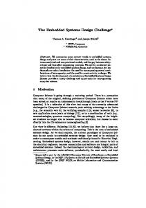
X-by-wire technology [118] shall allow ECUs to fully or partially automate a variety of mechanical systems like those controlling brakes or accelerator, e.g., Brake-by-wire. Recently, the steering-by-wire technology was introduced in commercial vehicles by the first time ever [143]. Several principles are being applied to secure embedded systems. As suggested in [85], the use of virtualization techniques may help to deal with interactions from attackers. By categorizing and separating ECU applications according to their exposure to threats, their exchanges can be better controlled and the system protected. It is considered [85] that Virtual Machines can be used to enforce security requirements in combination with tamper resistant modules like the TPM [194] or the HSM [198]. Just referred modules are the basis upon which ECU security is built since both can play the role of security anchors: they provide mechanisms to enforce platform integrity, authenticity, confidentiality, and freshness. Even so, TPM and HSM own different features. In particular, the TPM is standardized what favorably impacts applications development and portability. The HSM is not standardized but provides HW acceleration, modular architecture, more cryptographic primitives, and a Coordinated Universal Time (UTC) clock, all not supported by the TPM. Figure 2.1 shows the crosslayer modular composition of an ECU supporting security, safety, and user oriented applications. This architecture specification is borrowed from [13].
Figure 2.1: Modular structure of an applications ECU stack Figure 2.1 shows applications separation what allows to sanitize exchanges from untrusted sources. The architecture is composed by three virtual machines controlled by a central hypervisor named OKL4 [150]. A virtual machine is settled for containing SW modules in charge of overall security - leftmost box. The AUTOSAR [37] machine is in charge of standard automotive and safety oriented applications - box in the middle. Finally, user oriented and other untrusted applications are embedded in a separated machine rightmost box. On-board and off-board communicating facilities can also be installed within the user oriented virtual machine. To protect overall ECU architecture a security anchor is proposed. The root of trust enabling security for the ECU is the HSM proposed in [198]. Just described complexity is a challenge for achieving required applications performance, temporal constraints fulfillment, and also security. Platform complexity may impose difficulties to adequately analyze, design, and implement embedded systems [120].
13 ECU nodes distribution and configuration vary upon carmakers. Next paragraphs present two complementary on-board architectures that are under deployment and test. The SimTD initiative specifies ECUs architecture for achieving off-board communication, i.e., V2X communication. Complementary, the EVITA approach specifies on-board network mainly targetting secure in-car applications. The SimTD architecture [181] is intended for large scale vehicular communication networks. The architecture is divided in two parts, one harmonizing in-vehicle service components, and the second one comprising the infrastructure for services provided offboard. Thus, on-board architecture is mainly integrated by three interconnected ECUs with a modular crosslayer composition: CCU: The Communication Control Unit (CCU) that provides a link between on-board and off-board networks. Along with V2V facilities, the CCU provides Global Positioning System (GPS), Universal Mobile Transmission System (UMTS), WLAN and G5a,b connections for external services. For exchanges between internal components, the CCU supports CAN and Ethernet - LAN - protocols. The CCU behaves as a router directing incoming and outgoing message flows. AU: The Applications Unit consists of safety and non-safety related applications on the top of the crosslayer component. Middleware layer relies upon the Java/OSGI platform [152] and supports security modules, communication, navigation, and other services. Lower layer is the host Operating System (OS) Windows XP Embedded that holds the whole stack. HMI: The Human Machine Interface receives input from safety and non-safety applications in the AU. It provides driver with information via graphical and sound interfaces. Thus, Human-Machine Interface (HMI) is tightly coupled to AU operation.
Figure 2.2: Reference architecture for developing secure in-vehicle applications in the EVITA project The goal of SimTD architecture is to achieve an efficient platform for long distance wireless communication - WiMax, Long-range WiFi, GPS, Vehicular Ad-Hoc Network (VANET)
14
2. Security and Vehicular Applications
- necessary for safety oriented applications. On the contrary, the EVITA architecture specifies a secured platform mainly targetting on-board wired services. EVITA is aware about the integration of V2X technology. Thus, EVITA also supports short distance wireless communication like Dedicated Short-Range Communications (DSRC) and Bluetooth. The reference architecture for applications deployment is presented in figure 2.2. The reference architecture is a network of ECUs grouped in application-oriented domains. Each colored rectangle in figure 2.2 corresponds to an ECU. The domains contain a master ECU and several specific oriented sensor and actuator ECUs. The master ECU controls the domain and plays the role of gateway. The CCU links on-board architecture with external services, roadside communication architecture, and vehicles. Thus, CCU incorporates DSRC, UMTS, GPS/Galileo, and 802.x antennas. The CCU routes internal and external message flows by interacting with respective master ECUs and gateways. Many applications in charge of safety critical tasks like braking or vehicle steering are installed in Powertrain and Chassis and Safety ECUs, i.e., PTC and CSC, respectively. The Body Electronic Module ECU (BEM) includes applications usually activated/deactivated by the driver like lights, wipers, climate, and door locks. Infotainment applications are supported by the Head Unit ECU (HU). In addition, the HU may be in charge of safety critical applications and tasks like alert displaying and automatic emergency calls. EVITA architecture shows the complexity of current on-board networks.
2.3
Uncovered Security Aspects
In previous section an overview of automotive architectures was presented. This section highlights some uncovered security aspects taking the automotive architecture as reference. Since, uncovered security aspects may render automotive architectures vulnerable, several attacks are documented and explained. The respective impact of security vulnerabilities is also shown.
2.3.1
Critical Security Aspects
Security aspects that need to be considered in development and deployment of embedded applications are described in next items. Insecure Wired Channels: On-board buses like CAN, FlexRay, and Ethernet are open and accessible, e.g., by on-board ports connection. Above mentioned links are mainly conceived to fulfill functional and performance criteria but do not consider possible security threats. In particular, communicating protocols were originally deployed without assuming a hostile environment and little or no effort was put on securing [118]. Thus, packets can be seen and analyzed by whoever accessing the bus. Moreover, toolkits ease analysis of exposed material what underpins subsequent hacking procedures, e.g., via CarShark [121] and Wireshark [197]. Once a bus is sniffed, respective analyses can be conducted so as to assess scenarios and possible system vulnerabilities. Other advanced techniques like reverse engineering can be applied so as to reproduce code that emulates ECU applications. Among others, emulation code can be used for probing more elaborated attack scenarios and exploiting vulnerabilities. Also, techniques like random packet injection, replaying, and fuzzing may be enough for disturbing, disrupting or flooding on-board resources. The opportunities for a
15 hostile party targetting wired on-board channels depend upon physical access to non-protected links. Security protocols like IPsec [68] may provide certain protection to wired in-vehicle channels. Insecure Wireless Channels: Large and short range wireless links are supported by WiFi, Long-range WiFi, WiMax, UMTS, GPS, VANET, DSRC, and Bluetooth technologies. Some of those over-the-air channels like VANET and DSRC are open and accessible to anyone inside network range [97]. WiFi, Long-range WiFi, and WiMax were originally conceived with certain security which has been progressively improved but that may be breakable - see authenticity and privacy attacks in WEP and WPA [228]. Bluetooth technology has pursued secure communication but crypto schemes for confidentiality and authenticity have been repeatedly cracked - see [96]. Even if UMTS includes mechanisms for addressing integrity and confidentiality, eavesdropping and impersonation are possible [26]. Next generation of GPS technology has been recently introduced to protect against DoS and hacking attacks [191]. Along with security weaknesses, a variety of wireless analyzers and tools are available, e.g., Ufasoft Snif [205]. Consequently, intervention of third parties in over-the-air communications is possible. Based upon sniffing, analyses, reverse engineering, injection, replaying and fuzzing techniques, a hostile party can leverage himself to play an active role in safety critical scenarios whilst still being physically and virtually invisible. A remote attacker can dynamically intervene, fake, disturb or disrupt operation of safety critical applications like emergency alerts or braking [121]. In particular, authentication of vehicles has been identified as mandatory for ensuring VANETs operation. However, driver’s privacy concerns arise with respect to vehicle’s traceability. Proposed solutions to ensure privacy still need to be proved [91]. The operation of safety critical on-board applications - like broadcasting of cooperative awareness messages - depends upon adequate VANET operation and other over-the-air channels. Thus, security in wireless links impacts operation of safety critical applications. Applications Deployment: Several standalone off-the-shelf applications have been introduced in vehicles [78]. However, to our knowledge, the deployment of secure on-board distributed systems is still work in progress, e.g., [165]. As shown in the survey of section 2.1, distributed automotive applications have been developed mainly targetting functional and performance aspects and a late introduction of security is observed. Initial efforts for securing applications followed empirical approaches and effectiveness of overall security protections was not integrally proved. Several weaknesses in mutual authentication, privacy, availability, and confidentiality have not been overcome nowadays. Distributed applications that are non-secured can be attacked via insecure wireless and wired channels. For instance, the emergency braking application is distributed over CCU, HU, and CSC ECUs, thus, braking actions could be corrupted or false positive ones injected in CAN [121]. Along with channel side attacks, ECU stack can be infected via informatics viruses hidden in SW updates, downloaded applications or garage service transactions [179]. Once an application is overtaken by a hostile party, the impact on the overall on-board network is not negligible. An attacker may provoke application misbehaving, ECU isolation, or ECU disabling. If main ECU defenses are defeated, attacker actions may compromise not only on-board behaviour but also the neighbor vehicles. Lost of secret and private-sensitive material insecurely stored in SW is a potential risk of compromised ECUs.
16
2. Security and Vehicular Applications
Methodological Support for Securing: Many previous attempts for securing automotive architectures have mostly relied upon empirical paradigms. Overall concepts about what security is and methods for achieving it have been proposed [158]. Nonetheless, further methodological means can be tried in order to improve security, e.g., formal verification. A crucial objective is the assessment of achieved attack protection. Security countermeasures and mechanisms may be deployed to prevent only specific attack scenarios. In those cases, the system may crash in the presence of attacks not anticipated in analyses [97]. Since a security vulnerability may defeat overall ECU defenses, integral approaches ensuring adequate protection are of utmost importance. The fact that current vehicle architectures can be attacked [121], [179] shows that more interest should be put on securing and that securing methodologies need to be improved. Even if formal techniques have been mentioned as means to obtain the required methodological support [50], adequate integration into the engineering development process is still an ongoing and promising topic [42], [172].
2.3.2
Known Attacks and Potential Impact
This subsection presents a refined view of vulnerabilities in off-board and on-board vehicle embedded systems. As shown in [121], [179], if an attacker gains enough ECU control, several safety critical applications as those controlling, alerts, engine or even brakes can be compromised. By performing techniques like sniffing, target probing, and packet fuzzing over CAN buses, the attacker can lead to undermine the operation of applications, sensors, and actuators. Indeed, a hostile party can for instance: display arbitrary messages, speed-up and disturb engine, impede driver from starting or stopping engine, perform braking, lock or disable brakes, and freezing instruments panel [121]. Attacker capabilities can be increased by applying reverse engineering upon sniffed data. By doing that, the attacker may even fully drive the Body Electronic Module. Hence, attention is raised on the fact that vehicle architectures should be endowed with adequate security protections with regard to a set of potential attacks [121]. Table 2.2 presents a list of some known attacks associated to target vehicle assets. Some major consequences of the attack are also mentioned, e.g., with respect to security, safety, and driver’s economy. The list is descriptive and made according to the issues mentioned in previous subsection 2.3.1. It means that other relevant attack scenarios due to for instance dishonest owners or garage service providers are also feasible. For example, configuration/development tools like [67] and [213] can be used to modify ECU’s configuration so as to unbridle car’s engine. This kind of attacks are out of scope and consequently they are not addressed in this thesis manuscript. Table 2.2: Summary of attacks on automotive architecture assets and potential impact Asset On-board network
Attack Method Disabling communications by injecting halt commands in CAN bus [121]
On-board network
Drop, flood, modify, read, replay, spoof messages in the CAN network [123] Continued on next page
Potential Impact Safety: Engine is stopped whilst vehicle is on road. Overall applications become non-operational Safety: Overall vehicle misbehaviour. Security: Exploit protocol and applications vulnerabilities.
17 Asset ECUs CCU PTC, BEM
CSC,
Attack Method Turning ECUs to reflashing mode by command injection in CAN bus [121] Overpassing CCU access control protocol and loading SW applications [121] Know and override parameterized data by fuzzing CAN bus [121]
On-board network
Flooding network resources fuzzing wired links [121]
BEM
Reverse engineering on low speed CAN bus and fuzzing on high speed CAN bus [121] Fuzzing, analyzing, packet forging and injection on CAN bus [121]
CSC VANET, Wireless Network VANET, Wireless Network Wireless Network (CCU, HU) Wireless Network (CCU) Wireless Network (CCU) Wireless Network (CCU)
by
Tracing vehicles by sniffing periodic cooperative packets [181] Introducing faked alert/emergency messages [156] Disabling centralized vehicle access control [121] Fuzzing and flooding wireless network resources [121], [46] Flooding toll payment application resources [202] Corrupting toll payment confirmation packets [202]
On-board architecture (OBD ports)
Programming and flashing blank keys inside ECUs [47]
CD Media Player (HU domain)
Malware infection by infotainment firmware update or music file play (WMA) [179]
On-board network (ECUs)
Injection of malware by compromising and exploiting routing/forwarding devices of service center network [179]
HU (Bluetooth port)
Paired phone infected with trojan application provokes ECU buffer overflow [179] Continued on next page
Potential Impact Safety: Engine is stopped whilst vehicle is on road Security: Cyber viruses transmission Safety: Control of overall vehicle applications Safety: Intervene, disturb and disrupt communications. Full control of engine, brakes and body modules Security: Denial of Service Safety: Overall applications become non-operational Security: Control of all functions available in BEM domain Safety: Prevent brakes from being enabled. Perform abrupt braking at high speed. Blocking vehicle Security: Privacy of drivers threatened Security: Mutual authentication of vehicle nodes violated Safety: Vehicular network misbehaviour Security: Theft of secret information Driver’s economy: Vehicle theft Security: Denial of Service. Safety: DoS hides emergency scenario Security: Denial of Service. Safety: Car unable to pass toll road. Security: Re-execution of credit payment procedure. Driver’s Economy: Unnecessary recharge of toll credit tag. Security: Attacker disables vehicle protections. Safety: Vehicle unable to start. Driver’s Economy: Vehicle theft. Safety: Overall control of on-board vehicle system. Vehicle misbehaviour. Security: ECU defenses neutralized, malware dissemination, data theft. Safety: Vehicular network compromised at large scale. Vehicles misbehaviour. Security: Vehicular network defenses neutralized, virus spreading, massive data theft. Safety: Critical ECUs misbehaviour, e.g., Brake control ECU disabled. Security: Large scale trojan virus dissemination.
18
2. Security and Vehicular Applications
Asset CCU (UMTS)
Attack Method Neutralize CCU authentication by exploiting cell phone interface vulnerability [179]
Sensor ECUs and DSRC in CCU
Compromised Road-Side Unit (RSU)s and external spy nodes deliver and retrieve cookies to and from vehicles [25] Tampered sensor - e.g., at service garage - transmits vehicle position via UMTS or DSRC [25], [217] Exploiting authentication vulnerabilities in the remote keyless entry system for vehicle access [29]
Sensor ECUs and GPS in CCU On-board architecture (Closure System)
Potential Impact Safety: Attacker gains overall vehicle control. Security: Malware injection and dissemination. Secret data theft. Security: Vehicle tracked. Driver’s privacy compromised. Security: Vehicle tracked. Driver’s privacy compromised. Driver’s Economy: Vehicle theft
As can be seen from previous summary, several attacks performed via wired links can eventually be achieved remotely, i.e., via wireless channels. It implies that a remote attacker could virtually overtake vehicle’s control on the road and endanger vehicle and driver safety. Along with that, there also exist economical and privacy risks due to vehicle theft or disclosure of secret information, respectively. Thus, car-makers, OEMs, service garages, etc. may share legal and economical responsibilities with regard to potential stakeholders injuries. The technology required for threatening current and next generation automotive architectures is sophisticated but the motivations of hostile parties are quite enough to go ahead [169]. Fortunately, the existence of mentioned vulnerabilities has been mostly revealed in the scope of experimental tests and not in real scenarios. All in all, poorly protected distributed applications open the window to new threats that need to be properly prevented so as to protect human being safety, economy, and security.
2.3.3
Hypothetical Automotive Attack
This subsection shows a hypothetical attack instance that is inspired from the literature [121], [179]. The description shows up conditions that render hostile actions successful. The security issues discussed in subsection 2.3.1 are taken as a basis. Along with a more fine grained view of the attack, suggestions to vanish or limit attacker chances are afterwards proposed. The attack targets the Electronic Brake Control Module (EBCM) in the Chassis and Safety Controller (CSC) domain - see figure 2.2 - and is described in next items and in table 2.4. Attacker goal: Type of attack: Resources:
Lead to EBCM misbehaviour so as to prevent driver from braking Wireless channel attack Laptop with WiFi 802.11 ad-hoc connection, wireless network analyzer, 802.11 ad-hoc transceiver adapted with USB port, CAN-to-USB converter, knowledge on CAN bus protocol, knowledge on automotive on-board architecture
19
Initial conditions:
Physical access to on-board CSC CAN bus in the target vehicle(s)
Table 2.4: Actions to remotely compromise the Electronic Brake Control Module in an in-car network Attacker Action 0. Install network analyzer in spy laptop with WiFi 1. Attach a CAN-to-USB converter to CSC CAN bus in the target vehicle 2. Connect IEEE 802.11 ad-hoc transceiver to USB port 3. Follow target vehicle. Attacker is equipped with spy laptop 4. Sniff CAN packets 5. Identify EBCM packets transmitted during target vehicle braking 6. Apply reverse-engineering on sniffed packets 7. Program a hostile routine to automate and ease packet injection, e.g., to release, lock, arm, and fire brakes 8. Probe target vehicle by injecting forged/tampered/replayed EBCM packets 9. Re-try forged packet injection up to achieve EBCM misbehaviour 10. Inject fuzzed EBCM packets in the CSC CAN
Weakness/Condition Spyware technology available Vehicle on-board architecture is accessible Vehicle on-board architecture is accessible Target vehicle is unprotected against bus eavesdropping Messages in CAN bus are plaint-text based Attacker may subtly coerce target vehicle to brake in order to simplify EBCM packets capturing Practically unlimited time to conduct analyses. Sniffing can be conducted on the same or different target vehicles EBCM brake application operation can be determined from sniffed packets No authentication fields in CAN packet frame. No defenses implemented in EBCM brake application No intrusion detection system in the vehicle. Driver is unable to identify that car misbehaviour is due to an attack. No defense against DoS attacks leads to EBCM misbehaviour
Several aspects can be considered in order to limit attacker chances in the above hypothetical scenario. This shall improve security of the EBCM brake application. Initially, attack feasibility is not only due to weaknesses in embedded systems design. As can be seen from initial hostile actions in table 2.4, accessibility of overall vehicle architecture plays a crucial role in the attack - steps 1, 2. CAN bus design is a significant concern, since the protocol was not conceived with security in mind. Indeed, CAN packet frames do not include authenticator fields and consequently there is no mean - at network level - to filter messages from hostile parties. Also, since there is no protection of payload fields, plain-text messages can be interpreted by anyone accessing the bus - steps 4, 5. These weaknesses are enough to consider security
20
2. Security and Vehicular Applications
in embedded applications design as a primary aspect. For instance, cypher schemes may be settled to authenticate and keep secrecy of exchanges, e.g., Message Authentication Code (MAC), PKI signatures. Otherwise, sniffed packets can be analyzed to reveal overall behaviour of the application, as it is considered in steps 6 and 7. Once these weaknesses are adequately exploited, the attacker can repeatedly probe the vehicle and tune his strategy according to actions effectiveness - step 8. The strategy can be adapted to threaten other buses like FlexRay or Ethernet as well as other ECU domains. Acquired knowledge is also a basis to conduct attacks on applications distributed over wireless channels like VANET, WiFi or Bluetooth. A way to better protect the EBCM brake application is to make it secure by design. To do so, security techniques and principles should be considered from early stages of the engineering development phases. The effectiveness of security countermeasures like those for ECUs authentication can be formally proved against an attacker model what may improve system trustiness. Security analyses may also reveal the need for auxiliary components so as to deal with system weaknesses or vulnerabilities - as is the case in step 9 -, e.g., intrusion detection or watchdog modules. Monitoring components can include mechanisms to limit the impact in case of network flooding - step 10.
2.4
Conclusions
The security of current and next generation automotive architectures needs to be improved. To show it, a historical survey in the field of vehicular applications was presented. The survey roughly sampled several initiatives and projects made in previous decades. This state of the art depicted the evolution of automotive applications from early eighties up to now. The overview shows why security in vehicular domain was introduced. Along with that, the underlying on-board architecture of an ITS vehicle was presented. Referred architecture is a basis to understand complexity as well as uncovered security aspects in automotive embedded systems. Several efforts for securing automotive applications have been performed. However, many of those initiatives have not yet led to enough dependable on-board systems. Even if many standalone off-the-shelf applications are integrated in current automobiles, overall security in on-board architectures still needs to be improved. Originally, automotive systems were conceived mainly focusing on functional aspects. Designers were mainly concerned on achieving operability and performance and little attention was put on security aspects. The late introduction of security in the design process imposed an important gap between secured and implemented applications. The growing complexity of applications, components, and networks increased the challenge. The fact that applications were not conceived to operate in hostile environments influenced designers to introduce security as an add-on. However, that approach has resulted non-effective and new efforts are required to adequately undertake the problematic. The evolution of automotive applications shows that the objectives imposed to communicating vehicles were very ambitious. The efforts necessary to fully deploy such complex systems were likely underestimated. The initial works introducing security for protecting applications relied upon informal techniques. As soon as security weaknesses were identified and their possible consequences understood, a bundle of proposals for securing vehicular
21 applications and networks appeared. Unfortunately, relevant weaknesses were progressively identified in those approaches. For instance, the fact that applications were only partially protected, since requirements were elicited with respect to particular attack cases. Moreover, the effectiveness of security countermeasures to cope with attacks was not integrally proved. Even if several standalone mechanisms are security effective, the uncertainty about overall system protection remained. Formal techniques were early mentioned as a mean to enforce system protection. However, a gap still exists between off-the-shelf and formally verified applications. By adopting global-view approaches, the ITS challenge is better addressed. The joint efforts between industry and academy as well as the international collaboration for integration and standardization of applications show significant progress. Recently, more attention is put on the design phases as an early mean to secure and improve applications. Despite mentioned efforts, several uncovered security aspects have been revealed. Among others, the hostile environment in which automotive architectures operate along with accessible insecure channels still make distributed applications obvious targets of attackers. A lack of methodological support for effectively ensuring applications protection is identified. Inadequately protected applications may render the on-board network non-operational. Moreover, as it is shown in section 2.3.2, experimental tests demonstrate that current vehicle on-board networks are vulnerable what may undermine driver safety, security, and economy. Compromising the overall in-vehicle system requires sophisticated skills and tools. However, attackers may have enough motivations and resources for threatening vehicular networks and endanger ownerships and human being lives [169]. Security in embedded systems in general is a vast and very complex problem. After years of experience, the problem is better understood nowadays. Security is not easy to achieve, but improperly or not address it result more adverse. The fact that several systems considered secure have been finally cracked shows that security should be more thoroughly considered. In particular, that settled protections should be adapted to the evenly growing attacker capabilities, chances, and motivations. The introduction of technology like ITS is associated with known and new security threats. Explore approaches that accordingly improve embedded systems protection and limit attackers chances is of utmost importance. Development of embedded systems waits for more effective methodologies that improve security.
22
2. Security and Vehicular Applications
23
Chapter 3
Methodologies for Embedded Systems Verification As shown in previous chapter 2, there exists a need for improving security in embedded systems, in particular in the automotive domain. Some lacks in methodological support were also mentioned in subsection 2.3.1. More specifically, in the methods used to validate security features of automotive systems. A hypothesis that we adopt hereinafter is that formal techniques can be applied in order to improve certainty on that respect. Indeed, provided that security requirements are adequately elicited, formally verifying them over a system model provides certainty of security. Formal methodologies have been largely applied to improve concurrent systems [79]. We are particularly interested on analyzing how those techniques have been integrated into the engineering development process so as to verify security. The analysis shall show up methodological aspects that need to be better supported. The objective of this chapter is two fold. In a first step, the features offered by current verification methodologies will be precised. Thus, the phases of the engineering development process that are barely or not yet supported will be identified. In a second step, the features required by an overall verification methodology will be pointed out. To do so, several verification methodologies that can be applied to secure systems are analyzed. As shown in previous chapter, embedded systems may be safety critical and security weaknesses may compromise their operation. Accomplish security and safety objectives may depend upon functional and non-functional requirements. For instance, imposing a minimum key length for encryption is a functional requirement1 whereas demanding mutual ECUs authentication is a non-functional one, and both of them are security requirements. Similarly, specifying inputs/outputs for a facility is a functional requirement whereas demanding priority-based schedulability is a non functional one and both requirements may be safety critical, i.e, if they are not enforced, then something improper may occur to systems or individuals. That is why, our survey focuses on methodologies targeting verification of functional and nonfunctional requirements, and in particular security ones. An evaluation of methodologies is conducted so as to highlight their pros and cons, their capabilities for the verification of properties, and the usability of modeling frameworks. It will be finally concluded whether methodological aspects still need to be addressed for effectively achieve secured applications. Our approach is focused - but not limited - to analyze next aspects of methodologies: 1
Example provided by Professor Yves ROUDIER, http://www.eurecom.fr/∼roudier/
24
3. Methodologies for Embedded Systems Verification • Support for system development. The support provided by verification methodologies to the engineering development phases exhibits features, limitations, and adaptation of methodologies to the development process. • Verification of requirements. Capabilities for verification of functional and non functional requirements (security and safety) are worth having since embedded systems may be imposed to satisfy both of them. • Framework usability. The successful integration of formal methods into the engineering development process strongly depends upon how the modeling framework is adapted to user needs and skills.
Above criteria are chosen as a basis to evaluate verification methodologies and to assess their contributions for improving security. To simplify and order the analysis, methodologies are first classified. Proposed classification is a first step to settle metrics for methodologies evaluation. Next taxonomy is adopted: Generic Formal Theories: Generic theories or approaches providing a basis to perform formal verification. Generic Formal Based Tools: Toolkits based upon generic formal theories that are implemented to automate verification of properties in systems. Formal Security Oriented Methodologies: Formal theories, languages, and respective toolkits specifically developed or extended for verifying security in distributed systems. Cryptographic Protocol Oriented Approaches: Approaches and tools specifically targeting verification of so named security protocols. Model Driven Engineering Environments: Frameworks based upon the MDE paradigm addressing systems improvement and verification of properties, in particular security properties. They may rely upon formal languages and tools to conduct proofs. High Level Non-Model Driven Engineering Environments: Frameworks not based upon MDE approaches and assisting the engineering design process at a high level so as to automate verification, ease design, etc. Formal languages and tools may be introduced to conduct proofs. Certification Oriented Approaches: Approaches based upon international standards targeting certification of distributed systems, and in particular security. These approaches may rely upon automated provers so as to provide proof of requirements. Methodologies are classified in the category that better corresponds with their main characteristics. Even so, several of them may easily fit into two or more classes. Each category is defined through a level of abstraction, approach directives, main targets, and underlying backends. This taxonomy will be further refined for analyzing methodologies in more detail. The chapter is structured as follows. To achieve chapter’s objective, the survey in section 3.1 shows the main features offered by several verification methodologies. By doing that, advantages and shortcomings of each methodology are highlighted. To go more deeply,
25 in section 3.2, those features are refined and used to exhibit the support provided to the engineering development phases. Afterwards, the capabilities of methodologies for verifying properties are precised. Finally, an evaluation to assess the usability of design frameworks is carried out. So far, this analysis proves how current methodologies undertake the aspects highlighted in previous three-item list. The conclusions are finally presented at the end of the chapter in section 3.3.
3.1
Verification Methodologies Survey
This section shows several methodologies targeting verification in concurrent embedded systems. Methodologies are shown according to the taxonomy previously adopted. Descriptions mainly include modeling semantics, support for requirements modeling, and formal verification procedures. When adequate, other phases covered by the approach are described, e.g., code generation. A brief evaluation is provided what highlights main advantages and also limitations. The terms “methodology” and “approach” are used in the same semantical sense. It is nonetheless recognized that some of the items presented in the survey do not truly correspond with a methodology but only with a standalone environment, framework, tool, language, or method. They are even so analyzed due to their support and relevance for the engineering development process.
3.1.1
Generic Formal Theories
Generic Formal Theories provide the basis and semantics to conduct formal verification. Members within this category are Timed Automata [31], Petri Nets [142], Process Algebras [43], and Propositional Logics [76]. Rigorousness of languages and methods allows derivation of soundness results. Many formal theories define a semantics relying upon a state-transition approach. Timed Automata are among them and have been widely studied [109], [112], and used in verification of properties [31], [116]. Verification is usually conducted upon Computational Tree Logic (CTL) [183], a language appropriate for representation of reachability, liveness, safety, and deadlock freedom properties. Other variants of CTL representing time have been also used, e.g., Timed CTL (TCTL) [30]. However, none of those logics was conceived to proof security properties. In addition, Timed Automata is a generic approach that does not directly address any security aspect. Even so, as shown in [116], threats can be specified as an attacker automata whereas certain security properties can be expressed in terms of reachability, liveness, or safety formulas. Thus, the extent of results finally depends upon a security model entirely proposed by the user. Petri Nets have been also applied for modeling and verifying a wide variety of timed concurrent systems, e.g., [142]. As for Timed Automata, a semantics for verification of reachability and liveness properties is available [142]. In addition, the semantics allows verification of boundedness and reversibility. Contrary to liveness or reachability, boundedness settles thresholds for accomplishment of certain conditions whereas reversibility ensures that the net can return to a given fail safe status under any circumstance [142]. Security properties have been represented as Petri Nets that behave as security observers of the target system. An instance proving confidentiality is described in [127]. Other security sensitive systems, like security protocols, can also be verified relying upon Petri Nets approach. For instance, in [49] authenticity is expressed in terms of liveness and reachability formulas. Properties are proved with respect to states signaling correct system
26
3. Methodologies for Embedded Systems Verification
termination. For certain models, referred states must be visited a bounded number of times so as to avoid state explosion. Thus, attacker capabilities may be weakened and consequently the extent of certain proofs limited, e.g., liveness properties. The Process Algebra theory [43] provides formal languages whose operational semantics can be expressed as Labeled Transition System (LTS). Since verification of LTS is conducted upon CTL or TCTL logics, proof capabilities of Process Algebras are at least the same as for state-transition approaches, e.g., Timed Automata. Thus, shortcomings present in the latter ones may be also shared by Process Algebras, e.g., the state explosion problem. Temporal Process Algebras like LOTOS [203] have been early defined to represent many aspects of systems concurrency like parallelism, synchronization, and actions indeterminism. The extension of those algebras to model real time - e.g., RT-LOTOS [60] - allows verification of time constraints and also schedulability, i.e., feasibility of a schedule - see for instance [101]. Propositional Logics are generally based upon axioms, number, and set theories [76]. They differ from the finite state-transition paradigm and provide semantics for reasoning based upon boolean predicates in the form Conditions imply Conclusions. System models, properties, procedures for proofs, etc. are also expressed in terms of predicates. Due to its semantics, Formal Logics are adequate for representing richer notions of properties than those modeled in CTL or TCTL. But, the richer a semantics is, the more elaborated a proof may result. Thus, settle algorithms to automate proofs may be complex. Non automated/hand made proofs may dramatically increase the time spent in verification phase. Generic Formal Theories are the support for other verification methodologies that do not have themselves a formal semantics. Nonetheless, Formal Theories do not provide explicit means for addressing many relevant engineering concerns like security. Indeed, analysis and modeling of threats, elicitation and modeling of requirements, and support for results interpretation should be addressed by the designer and without any assistance. By letting the designer conceive a security framework, several design choices may not be appropriately taken, e.g., with respect to threats model accuracy. Consequently, the validity and scope of verification outcomes may result badly biased by choices taken at design. For instance, weakening attacker capabilities beyond real conditions may render verification results inappropriate. Other Generic Formal Theories not based upon the state-transition paradigm, like mathematical logics, have similar limitations.
3.1.2
Generic Formal Based Tools
This category contains tools strongly linked to formal theories described in previous subsection. For instance UPPAAL [211], Atelier-B [57], Isabelle/HOL [207], and CADP [108]. Tools in this category provide SW support and a framework upon which modeling and verification can be performed. Along with a modeling frontend, the automation of verification is a major advantage. Implemented algorithms and procedures to conduct proofs decrease error risk and speed up verification phase. Even if graphical support may be provided, framework language - i.e., symbols, syntax, and semantics - is mostly inherited from respective formal theory. The UPPAAL framework implements and extends the Timed Automata approach [90]. UPPAAL extends Timed Automata semantics by introducing data types, variables and constants. Introduced constructs allow definition of broadcasting synchronous channels and
27 support more complex structures that enlarge modeling capabilities [211]. Time elapses in a global and continuous scale and each automaton is able to count time via a finite set of variables named Clocks. Clocks can be set, reset, and used to specify time constraints. Along with reachability, safety, liveness, and deadlock freedom properties, UPPAAL allows verification of bounded liveness. A bounded liveness property declares events that should always occur before an upper time threshold. Properties are verified in an extension of CTL [109]. Due to its features, UPPAAL is suitable for conducting time constraints analyses including schedulability [223]. Some security properties have been also verified. As shown in [139], temporal RBAC policies are verified via an observer automaton. In [116], authenticity, secrecy, and freshness are verified in terms of states signaling correct automata termination. It is highlighted that security properties are verified even without a threats or attacker model. Thus, the resistance against attacks or threats is not evaluated. The B method and tools offer a formal framework based upon Abstract Machines logics [23]. The syntax has a resemblance with a programming language making it adequate for SW systems development. The method relies on machine specifications - named theories based upon the mathematical concepts of refinement and function. By applying sequential refinements to an initial Abstract Machine, a final SW application can be generated. B method ensures that properties verified upon an Abstract Machine are preserved by its refinements. In the B context, properties are named proof obligations and are represented as logical propositions in the form Conditions imply Conclusions. Proof obligations are settled so as to verify machine correctness that is defined by associations between function inputs and outputs. Composition of Abstract Machines is allowed. However, no semantics is available for modeling synchronous or asynchronous communications what may be necessary in concurrent systems modeling. The Event B Method has been introduced to undertake just mentioned limitation [44]. Even so, B semantics does not support real-time analyses and no security concern is originally addressed. Among the main facilities offered by B-tools are model animation, type analysis, assisted generation of proof obligations, interactive proofs, and code generation and execution [57]. Proofs termination in B logics may require human aid what demands formal knowledge. The B method has been used as underlying verification framework by other security oriented approaches [52], [99] that are discussed in respective subsections. Isabelle/HOL is a theorem prover that has been applied in verification of concurrent systems. The framework combines the theorem prover Isabelle, with a High Order Logic (HOL) [207]. The syntax has alikenesses with a logic programming language - e.g., Prolog. It also follows an axiomatic structure. Expressions may be composed by basic types, variable declarations, functions definitions, logical predicates, theorems, and proofs. Thus, properties to be verified are expressed as theorems, lemmas or rules. As for any high order logics, just mentioned expressions are written as Horn clauses, i.e., in the form Conditions imply Conclusions [201]. Classical methods like induction and deduction are applied when proving properties. With the exception of code generation, verification capabilities and limitations of Isabelle/HOL are the same as for B method. Security properties have been modeled and verified relying upon Isabelle/HOL. In [74] for instance, RBAC policies are verified against “arbitrary” users. But it is not discussed to which extent conducted verification relieves the explicit introduction of an attacker model. On the contrary in [176], a Dolev-Yao adversary [14] is introduced and authenticity and data secrecy verified. The notion of time is modeled relying upon sequential indexes that allow verification of message freshness. Nevertheless,
28
3. Methodologies for Embedded Systems Verification
the adversary is barely described and strongly biased by the targeted instance. It is also highlighted that proofs are user interactive and become complex - even for simple instances - thus demanding skills on logics and formal knowledge. As can be noticed, Generic Formal Based Tools are tightly coupled to the formal theory upon which they depend. Even if a modeling frontend is provided, the syntax remains formal and almost unchanged. The aids provided at frontend may improve approach comprehension and usability. All in all, the support provided to engineering development phases like system analysis is minor. In addition, properties modeling capabilities are mostly focused on functional, time constraint, and schedulability proofs. Since no security concern is directly supported by the tools, modeling of security concerns mostly depends upon designer experience. Several limitations already mentioned in subsection 3.1.1 are inherited by these tools.
3.1.3
Formal Security Oriented Methodologies
Methodologies in this category extend a Generic Formal Theory - see subsection 3.1.1 so as to address security concerns. As representative instances are Avispa/HLPSL [184], ProVerif [2], and SHVT [84]. Among the main security aspects to be formalized are a threats model, definitions of security properties, means for modeling typical security-related structures, like crypto primitives, and procedures/algorithms to conduct proofs. Along with formalization of security concerns, toolkit support is worth having so as to reduce proof error risks and speed up verification process. Modeling languages and security extensions mostly remain formal. Methodologies in this category mainly focus on modeling and verification phases. Certain tools also provide aids to ease results interpretation like traces showing vulnerabilities. Avispa/HLPSL provides a high level language for modeling security-oriented applications and an interface for conducting automated proofs [184]. The syntax follows a state-transition approach, even if HLPSL is mostly a dialect of the π-calculus [168]. The semantics is appropriate for modeling communicating entities of distributed systems. Patterns for modeling cryptographic primitives and Dolev-Yao channels [14] are available. The intruder controls exchanges over public channels whereas his initial knowledge is specified by the designer [94]. Rules defining intruder capabilities are already specified in the Avispa tool. Thus, strong and weak authenticity can be verified relying on the concepts of injective and non-injective agreements [129], respectively. Also, secrecy of data can be proved. The verification approach exploits the capabilities of a variety of checkers like OFMC, CL-AtSe, SATMC, and TA4SP [35]. The system and attacker behaviours are finally represented at backend. According to [35], Avispa/HLPSL is able to recognize many known security vulnerabilities in protocols. Nevertheless, its capabilities to uncover security vulnerabilities are limited since some checkers are blind to recognize intentionally flawy systems [35]. To overcome this limitation a translation of Avispa/HLPSL models towards ProVerif has been proposed [94]. It is highlighted that Avispa/HLPSL semantics provides no structure for modeling functions other than crypto ones and that time analyses are not supported. ProVerif is an extension of the spi-calculus [22] that was early proposed in [21]. Along with a formal syntax, ProVerif offers an automated framework suitable for security proofs [2]. In ProVerif, communicating entities are modeled as processes that interact via public or
29 private channels. A border between public and private domains is introduced. That border allows definition of private and public variables what also splits the initial knowledge. A major contribution of ProVerif is its formally defined Dolev-Yao attacker [38]. ProVerif’s attacker is specified in terms of rules defining privileges over public channels. The semantics allows modeling and verification of strong and weak authenticity, and data secrecy. Formal structures are also available for modeling security elements like crypto primitives and other functions. Another major contribution of ProVerif is its automated resolution algorithm. It applies several techniques so as to settle a bounded and representative space of Horn clauses that ensures soundness of proofs and upon which properties are automatically proved/disproved [54]. It is even so recognized that the algorithm is blind for identifying message order [54] what limits verification capabilities. The proof algorithm relies upon the unification technique that search for equivalent predicates. Identifying semantically equivalent predicates may fail what may lead to infinite searches or loops. Some techniques are suggested to cope with that shortcoming [45]. However, it is recognized that infinite searches and loops may still appear [45]. Even if ProVerif has been thoroughly developed, time modeling is not supported. Consequently time-based properties like freshness are not easy to address. This shortcoming also makes not obvious the verification of authenticity in exchanges that rely upon time-stamps. The SHVT/SeMF is a formal approach based upon the concepts of automata composition, simple homomorphism, and preservation of properties [148]. The methodology is supported by a toolkit [84]. In SHVT, system components are modeled as automata that can be composed. The concept of simple homomorphism is introduced to simplify automata structure whereas certain properties are still preserved. Approximations are introduced in order to cope with the state explosion problem [149]. The properties preserved under simple homomorphisms rely upon a weakened version of liveness: conditions should be satisfied at least in one possibly infinite continuation for all paths. Formal structures for proving authenticity and secrecy are introduced in [171]. The so named Security Modeling Framework (SeMF) conceptualizes security as the ability of a component for identifying correct and incorrect actions with respect to its limited view of the overall system. Even if an attacker is not explicitly modeled, its behaviour is implicitly considered in sequences including incorrect actions. As shown in [32], the SeMF has been complemented with formalizations for non-repudiation and data-traceability, the latter necessary for proving privacy. As major limitations, SeMF has not been fully integrated in the SHVT toolkit what is a major disadvantage with respect to Avispa/HLPSL and ProVerif. Since SeMF language is highly complex and proofs of properties are hand-made, strong formal skills are demanded. Also, time spent in verification may dramatically increase even for simple instances. As shown in [19], the approach has been applied for securing industrial automotive applications. Nevertheless, time-based analyses are not addressed and security properties like freshness not yet introduced. Security Oriented Formal Methodologies provide explicit means for modeling and verifying some security properties. Among them are Strong and Weak Authenticity, Data Secrecy, Non-Repudiation, and Data Traceability. Methodologies introduce explicit or implicit threats models thus relieving designers from that task. Attacker models aim to be generic, i.e., independent of a system model, and are specified to stress the system so as to validate targeted security properties. These features ensure soundness of verification results. Procedures and algorithms for proofs may be implemented in automated or
30
3. Methodologies for Embedded Systems Verification
interactive provers. The syntax remains formal and little adapted for assisting tasks in the engineering development process. Methodologies in this category are not suited for performing functional, time constraint, or schedulability analyses. This is a limitation for directly modeling security properties that are time dependent like freshness. In addition, other relevant security properties like controlled access and integrity are not covered.
3.1.4
Cryptographic Protocol Oriented Approaches
The need for open channels to realize communication is a main source of security risks. The limited view of communicating entities along with insecure/flawy implementations may be exploited by attackers so as to disrupt, disturb, intervene or gain control. As shown in chapter 2, attacker actions may badly impact safety, economy, trustiness, and authority of stakeholders, cryptographic service providers, and/or makers. That is why, approaches adapted to verify so named security protocols are of utmost importance, e.g., KL(n) [71], AIF [137], and Avispa/HLPSL [184] - already shown in previous subsection. This section shows the capabilities of some paradigms targeting security in protocols. Among primary concerns are modeling languages, supported security properties, procedures for verification, and formal backends. Identified drawbacks are also discussed. The work in [72] proposes protocol modeling and verification on the linear-time temporal logic of knowledge KL(n) and S5 [71]. Predicates rely upon three main components: knowledge, operations, and quantifiers, and take the form Conditions imply Conclusions. A protocol is modeled as a set of predicates settling assumptions, axioms on knowledge, and communicating policies. Agent’s behaviour is modeled as a set of rules specifying its initial knowledge, starting rule, and actions to be performed afterwards. The attacker should be specified by the designer as a particular agent of the protocol and also relying upon predicates. The space of search is built by states defined by agent’s knowledge and actions declared in predicates. Authenticity, secrecy, and non-repudiation can be modeled as reachability, safety or liveness formulas. As main limitations, security definitions are not generic and strongly depend upon protocol states what limits their re-usability. A resolution method based upon standard elimination and simplification techniques is proposed [71]. The method is not fully automated and human interaction is required. In addition, no semantics is available for modeling multiple protocol executions (parallel or sequential). It implies that the attacker intervenes in at most a single system run. Thus, soundness of proofs is strongly limited by this shortcoming. As shown in [116], UPPAAL automata can be used for modeling and verifying security protocols. In this approach - denoted by AK − BK -, protocol agents are modeled as timed automata that interact via an attacker automaton. The attacker automaton is modeled by the designer based upon a Dolev-Yao paradigm [14]. A technique for modeling crypto primitives is proposed and applied. Modeling security properties depends upon states indicating correct protocol completion. Thus, authenticity and secrecy properties are accordingly verified. Timed automata allow delays measurement what allows verification of freshness properties [116]. Verification is automatically conducted by the CTL verifier implemented in UPPAAL [211]. In order to avoid the state explosion problem, several simplifications should be introduced. For instance, random attacker capabilities are weakened by constraining its transitions. In addition, a single protocol run is allowed in each agent automaton. Introduced simplifications strongly limit soundness of proofs and moreover
31 may render results non-realistic, e.g., in the case of freshness. Proof of certain properties, like strong authenticity, are a trivial consequence of scenarios without multiple protocol executions (parallel or sequential). The AIF-framework [137] depends upon a logics quite similar to KL(n) . The main difference is that the number of actions of honest or dishonest parties is unbounded what enriches verification capabilities. A protocol is modeled based upon sets of parameters like agents names, keys, nonces, etc. A protocol state is defined by a combination of predicates and operations over parameter sets. Transitions between states are settled as clauses in the form Conditions imply Conclusions. Possible attack states should be identified and declared by the designer. Attacker capabilities are specified as transition rules leading to attack states. Instead of properties, anti-properties are defined, i.e., clauses declaring sufficient conditions for leading to attack states. Thus, anti-properties for violation of authenticity and secrecy are exemplified. Since the logics does not support modeling of time, a discrete scale is emulated what allows verification of a discrete version of freshness [137]. Models are proved either in ProVerif [2] or on the theorem prover SPASS [133]. As main limitations, proofs in SPASS require human aid for termination what demands formal skills. The specification of the AIF attacker model and its relation with the ProVerif attacker must be thoroughly justified. Finally, anti-properties strongly depend upon protocol states what compromises their re-usability. Approaches in this category provide some means for modeling and formalizing protocol elements and security properties. Since modeling threats is not a simple issue, protocol approaches demand specialized knowledge in security and logics. As it is shown, languages are formal and not suited for assisting engineering development tasks. As major limitations, threats models are not thoroughly introduced. Moreover, simplifications in system and/or attacker models may limit scope of results and make them unrealistic. Verification of Authenticity, Secrecy, Freshness, and Non-repudiation is covered. Security properties like RBAC and Integrity are not supported by the above approaches. Recent work on protocols verification introduces the notion of dynamical verification of protocol thus extending the traditional validation on a single protocol definition [58]. Such kind of approach shall allow on-the-fly verification of a protocol family according to the constraints imposed by the context scenario and the options of the end-point entities [58].
3.1.5
Model Driven Engineering Environments
Model Driven Engineering (MDE) environments assist system design at a high level of abstraction [5]. Approaches in this category provide languages that pursue the improvement of systems. A representative instance is the Unified Modeling Language (UML) standard [10] which is broadly known and used. That is why, the environments shown in this subsection are UML-based. Most UML-based approaches targeting formal verification follow a similar path: they settle an UML framework suitable for modeling systems and requirements at a high level. Since UML is informal, models are later translated to a formal backend upon which verification is conducted. All in all, UML-based environments are standalone and may not include formal verification. This subsection shows capabilities and limitations of some environments with and without formal techniques support. The Systems Modeling Language (SysML) [190] was defined by the OMG [7] for specify-
32
3. Methodologies for Embedded Systems Verification
ing, analyzing, designing, and verifying concurrent systems. SysML extends the UML profile by re-defining Block and Activity Diagrams. In addition, Requirement and Parametric Diagrams are introduced. SysML extensions aim to better support analysis and modeling of concurrent systems. Moreover, requirements and constraints imposed over safety critical systems can be accordingly structured. Two SysML-based frameworks that also have toolkit support are Artisan [36] and Rational Rhapsody [105]. Artisan and Rhapsody offer C, C++, and Java code generation from models. An important shortcoming is that SysML-based approaches are not adapted for modeling security concerns. Several UML profiles have been introduced for fulfilling semantical lacks not covered by UML nor SysML, e.g., SecureUML [128] and UMLsec [113]. SecureUML introduces constructs for modeling and verifying RBAC policies. The profile is defined by a language that generates designs close to a software implementation what is useful for code generation [216]. Security RBAC policies are modeled as formulas in the Object Constraint Language (OCL) [6]. Proofs of policies are conducted upon formal backends and assisted by environments like Isabelle/HOL-OCL [24]. SecureUML is mainly oriented to prove access control policies and no attacker model is explicitly introduced what may limit its capabilities for addressing other security properties, e.g., authenticity. The main extension in UMLsec is the security link between classes and objects. Introduced links can be defined by formal constraints that specify their features. Thus, secret and public communicating channels can be defined. Along with formal constraints, the link stereotype provides means for specifying attacker capabilities. According to the authors [114], security properties, like authenticity, secrecy, and integrity can be modeled as formal constraints imposed on respective links. Several proposals have been made in order to formalize and verify UMLsec models - see [114], [12]. An important shortcoming is that a generic attacker is not yet fully specified what limits soundness of proofs. In addition, security properties should be defined and formalized by the designer. Verification of UMLsec models relies upon Computer Aided Software Engineering (CASE) tools, theorem provers like Isabelle/HOL -, and other verification engines [196], [12]. The VERTAF approach [154] provides an UML-based framework suitable for schedulability analyses and model checking [154]. Properties to be verified are defined as OCL formulas [6]. The main characteristics of this methodology are grouped in three categories: system models, formal synthesis, and formal verification. System models are made in almost pure UML what allows model portability. Synthesis is conducted in two phases: scheduling and code generation. The scheduling phase is conducted so as to prove - or disprove - that system model satisfies temporal and spatial constraints due, for instance, to priorities in scheduling or buffers size, respectively. Formal verification is finally conducted upon a built-in model checker that directly displays design errors on UML designs. Also, portable code can be automatically generated from models. It is claimed that preservation of verified properties is ensured [154]. Even if functional and non-functional analyses can be performed, the methodology does not address security at all. The framework may require major modifications in order to include security analyses capabilities. Other approaches similar to VERTAF are OMEGA2 [146] and MARTE [195]. TURTLE [33] provides methodological support for requirements structuring, analysis, design, and verification of timed concurrent systems. System design is based upon extended UML Classes and Activity Diagrams. TURTLE classes are defined with attributes and
33 gates that support exchanges between classes. Gate connectors can be associated with an operator that settle conditions for classes execution like parallel, sequential, and preemption. Class behaviour is modeled in an Activity Diagram defined with several order and time based operators. Introduced semantics is appropriate to model several deterministic, indeterministic, ordered, and time-based events in concurrent systems. Properties to be verified are represented as observer classes that include error states signaling property violation [81]. TURTLE exploits verification features of three formal backends: UPPAAL [211], LOTOS [203], and RT-LOTOS [60]. Thus, the framework provides adequate support to the engineering development process and is suitable for time-based analyses and verification. However, as it is shown in [19], security concerns like a threats model should be completely conceived by the designer. Along with that, introduced simplifications to avoid the state explosion problem strongly limit the extent of security proofs. A main characteristic of the approach presented in [56] is that UML modeling is formally guided. A method is presented for representing system and RBAC policies as an automaton. Each state represents a subject accessing an object whereas transitions respectively enforce access policies. Some guidelines are given to manually translate the automaton into UML class and statechart diagrams. Contrary to previous approaches, the modeling language relies upon pure UML, i.e., no extension is defined. The approach shows how to prove confidentiality relying upon Linear Temporal Logic (LTL) formulas. UML models are translated to PROMELA and formal verification is conducted upon the SPIN model checker [185]. SPIN is able to display counter examples in case of property violations. The main limitations of this UML/SPIN approach are the absence of an explicit attacker model, needed to prove certain security properties, and means for modeling concurrent systems like communicating channels. The goal of the AORDD methodology [89] is two-fold: achieving secure designs and efficient system performance/throughput. To achieve this, system assets and behaviours are represented in standard UML diagrams. Based upon the Aspect Oriented Approach [83], attack cases and respective security countermeasures can be selected from object libraries. Later, they are accordingly integrated into the system model. Properties ensuring system resilience are represented in OCL semantics [6]. Verification is finally conducted by translating the integrated UML model into the Alloy analyzer [189]. The model checker displays traces whenever a property violation is discovered. Traces are automatically interpreted and translated as counterexamples at UML level. Finally, an analysis is proposed so as to explore and find a cost effective and time-adapted security design based upon Bayesian Networks [89]. A drawback of AORDD is that security analyses rely upon specific attack sequences what may limit overall system protection. Indeed, protect against a specific attack is not as effective as protect versus a generic attacker model. SecureMDD [138] is a MDE approach that models static and dynamic parts of systems in standard UML Class, Deployment, and Activity Diagrams. UML is extended with stereotypes that model security constructs like crypto functions. The extensions of deployment diagrams provide means for specifying system architecture and attacker actions, e.g., over ports and connectors. In order to conduct verification, SecureMDD models are translated towards the high-order theorem prover KIV [206]. Attacker actions are specified by the user at UML level and are later transformed to KIV what settles a Dolev-Yao attacker [14]. Properties to be verified are expressed as theorems in the form Conditions imply Conclusions.
34
3. Methodologies for Embedded Systems Verification
Once models are verified, a second transformation towards the Model Extension Language (MEL) can be performed [138]. Translation to MEL allows automatic generation of Java code from models and integration of hand-made code. An important shortcoming is that perturbation of verified properties due to handmade code is not addressed. In addition, any mean for modeling security properties at UML level is available. Finally, formal skills are needed for modeling security properties in KIV and assist the tool in proofs termination. MDE-based environments provide means well adapted to the engineering development process. They rely upon semi-formal and standard languages oriented to analyze, structure, and model systems at a high level. To conduct security analyses, features of the system context and threats model are introduced. Several environments in this category target verification of functional and non-functional properties, e.g., time constrains, absence of misbehaviour, and also security qualities. Those approaches automatically transform UML models to underlying backends in order to conduct proofs. Along with that, certain support for results interpretation is provided, e.g., translation of violation traces to UML sequences. A main goal of MDE-based verification is the generation of code from models. Since the integration of handmade code may perturb verified properties, how to ensure properties in a final implementation is still an open topic [41]. Many MDE environments targeting code generation still need to address that issue.
3.1.6
High Level Non-MDE Environments
Environments in this category are seen as non-standard approaches that pursue similar goals as their MDE counterparts. It is assumed that Non-Model Driven Engineering environments - denoted as N-MDEs - are not based upon the MDE paradigm and provide support to the engineering development process at a high level. Thus, N-MDEs also rely upon underlying backends to conduct proofs. A vast majority of works to assist design at high level are MDE-based. Consequently, only a few N-MDEs are found in the literature. The main features and limitations of some of them are discussed in next paragraphs. The KAOS approach is thoroughly presented in [188] and [52]. KAOS proposes secure system development oriented by requirements. Each element in the modeling language combines informal and formal syntaxes. KAOS modeling is mainly based upon four constructs: Goals, Responsibilities, Objects, and Operations. Goals are meant to define, structure, and refine security requirements and attacker actions specified as obstacles. In Object modeling, refined goals are associated to system elements that should achieve goals thus providing obstacle mitigations. Similarly, a Responsibility is meant to assign refined goals to an expected stimuli - or response - from external system components. Finally, an Operation associates stimuli/response events from external components to elements within the object model. The main contributions of KAOS are the semantics and respective method for analyzing, structuring, and refining security requirements and obstacles. Verification of KAOS models is conducted on underlying formal backends like B-based tools. As shown by the FADES approach [99], a translation of KAOS onto B abstract machines is feasible. Along with translation rules, a method is proposed for eliciting and refining obstacles - i.e., attacker actions - from negated security goals. FADES exhibits a smooth transformation from high level modeling up to a final implementation. This feature may ensure properties preservation across model-to-code generation process. It is identified that eliciting and refining obstacles from negated goals strongly depends upon designer experience. Moreover,
35 no attack assessment is addressed at all. System countermeasures are not formally proved so as to ensure that refined obstacles are truly prevented. Since goals and obstacles are directly modeled in linear or high logics, formal knowledge is demanded. Also, the lack of support for modeling time, links features - like public/private -, and communicating policies are major shortcomings. The Software Architecture Modeling (SAM) is a high level methodology for SW and threats modeling and for verification of properties [100]. A design is composed by component architecture diagrams - representing system assets - and simple or timed Petri nets - modeling assets behaviour. Thus, properties can be represented as CTL or TCTL formulas. SAM provides a procedure for elicitation of threats targeting system assets. Threats elicitation is performed relying on a basic set of attacks: Spoofing, Tampering, Repudiation, Information disclosure, Denial of Service, and Elevation of privilege, i.e., the STRIDE model. SAM methodology performs an iterative refinement process between threats and system model [28]. The iterative process eventually introduces attack mitigations in the system under design. Among SAM mitigations are logical constraints, architecture countermeasures, and security modules. In order to verify that mitigations truly cope with respective threats, SAM models are translated towards the Symbolic Model Verifier (SMV) [55]. If a property is violated, SMV provides traces that are translated as sequences in Petri net diagrams what starts an iterative process for design remodeling. As main limitations, the procedures for attack refinement and properties elicitation strongly depend upon user experience. System and properties modeling are formally developed and demand formal skills what may impose limitations to non-experimented designers. Last but not least, elicitation of attacks and security properties out of the STRIDE model is not covered. SecureTropos targets development of secure software oriented by goals [208]. The methodology addresses not only features of the Information Technology (IT) but also the procedures and policies of the organization in which it operates. Several phases of the engineering development process are supported: requirements engineering, system design, and formal verification. SecureTropos introduces a graph semantics where actors, their goals, and the tasks and resources for achieving goals are modeled as nodes. Associations between nodes help to declare objectives, capabilities, trustiness between actors, and permissions and orders [132]. By refining this goals model, IT architecture elements can be identified and modeled with the aid of security patterns [132]. IT and organization components are modeled in the Agent Unified Modeling Language [208]. Design, formalization, and verification of models is supported by the SecTro toolkit [193]. Behavioural properties are automatically verified in a temporal logics [86] whereas security properties are proved in an Answer Set Programming logics similar to Prolog [92]. The methodology has been mainly applied to prove authenticity, authorization, and privacy [132]. Explicit attackers can modeled as any other actor in the system. The refinement of attackers, goals, and IT models entirely depends upon the designer what demands security skills. Since security properties are written as linear formulas, formal skills are worth having. Along with that, SecureTropos does not offer code generation and time-based properties are not supported. As can be noticed, N-MDEs share similarities with their MDE-based counterparts. They both provide a good support for modeling system, threats, and functional and non-functional requirements. N-MDEs also address formalization, transformation, verification, and code generation stages. Nonetheless, N-MDE modeling is mostly made on formal languages
36
3. Methodologies for Embedded Systems Verification
which are less adapted to the engineering development phases. In particular, for the stages typically performed on informal languages like system analysis. Last but not least, since either system or properties should be formally modeled, formal skills are demanded to designers.
3.1.7
Certification Oriented Approaches
The Common Criteria (CC) [3] became a significant reference for security evaluation of IT systems. Common Criteria were jointly elaborated by several organizations over the world settling a documentary basis for security assurance of technologies. The agreed Common Criteria are granted to ISO/IEC and written as the standard ISO/IEC 15408 [187]. ISO/IEC 15408 provides language, categories, and requirements for achieving system certification in one of the seven Evaluation Assurance Level (EAL). The higher assurance level is pursued, the more and more stringent exigencies imposed over the system. Since CC and ISO/IEC 15408 do not provide any methodological support, several efforts have been conducted targeting both certification of systems and formal verification. This section is dedicated to show the capabilities and shortcomings of some approaches that combine CC and formal verification. Just referred approaches assist system design and ease integration of the standard into a specific formal framework. As for other high level methodologies, underlying formal backends are required to conduct proofs. The CC classify security requirements into two categories: functional and assurance. Functional security requirements should be undertaken by functions within the system whereas security assurance requirements are imposed on processes for system design and deployment. Requirements are stated according to pursued EAL certification. The so named Target of Evaluation (ToE) is defined in a core document named Security Target (ST). The ToE precises system assets as well as respective threats. The ST also includes a description of security objectives to achieve assets protection and threats prevention. Functional and assurance requirements may be specified as security objectives. Thus, a final ST should include a whole description of the functions and assets composing the ToE, respective threats, and security objectives. The PalME approach [215] proposes a mapping of CC requirements to system development phases. A schedule states how and when CC requirements should be addressed according to the system development process. The engineering process is conceptualized in several phases: planning, analysis, design, implementation and testing, and delivery and operation. Threats analysis and security countermeasures partially define the ToE and the ST which are further precised during design phase. The design phase is developed on the AutoFocus tool [204] that supports several modeling profiles similar to UML. The testing phase is performed using attack sequences defined during analysis stage. Tests are mainly settled to provide evidence for targeted EAL certification. To conduct formal proofs, models are automatically translated to the SMV prover [55]. Thus, properties should be directly modeled in LTL or CTL logics. Since neither elicitation nor formalization of properties are assisted, formal knowledge is demanded to designers. In this approach, even if formalized CC criteria are satisfied, the effectiveness of threats countermeasures may not be formally ensured, since the proofs are conducted without a generic attacker model. Indeed, the security protections are settled with respect to specific attack sequences. The methodology in [140] proposes formalization of the target of verification - ToE -
37 and respective CC requirements in the Z language [175], a dialect originally used for developing the B method. The methodology is focused only in functional security requirements. Accordingly, a library of Z templates covering the whole functional CC specification is claimed to be available [140]. Along with templates generation, the approach describes the phases for verification of the ST. First, the target system is modeled in Z language. Z templates are selected according to the pursued EAL certification. Afterwards, selected Z templates are instantiated what defines the properties to be verified. Finally, verification is performed upon Z/EVES [151], a theorem prover similar to Isabelle/HOL or SPASS. As main shortcomings of this work, since system and properties should be modeled in Z, formal knowledge is needed. Formal skills are also required in order to assist the tool in proofs termination. Along with that, no explicit threats model is introduced. Consequently, even if formalized CC requirements are satisfied, system protection against attacks may not be formally ensured. Just presented CC-based approaches provide certain support for integration of ISO/IEC 15408 requirements into the engineering development process. In particular, good support for modeling security requirements is provided. Formalization of models and automated or interactive verification are mainly addressed. Since modeling of system and requirements is formal, certain skills are consequently needed. Some similarities between above approaches and KAOS exist, e.g., the design is oriented by requirements. Although, the CC [3] provide an extensive documentary basis to derive security requirements and to test relying upon vulnerability analyses, what is not available in KAOS. The CC are also the basis for a so named Common Evaluation Methodology [3] that is intended to evaluate the security of IT systems and assign an EAL certification. The combination of the CC and formal techniques is meant to improve the methodological support to the evaluation process.
3.2
Qualitative Evaluation of Verification Approaches
Verification approaches are evaluated with respect to the support provided to the engineering development process. Thus, evaluation features are elicited considering the different phases of the development process. They are shown in table 3.1. Most features are refined in subcategories associated to a code ID. Code IDs are useful for assigning qualities to methodologies in a simplified manner. Table 3.1: Features of verification methodologies Feature System Design Support Requirements Structuring Aids Threats Structuring Aids Translation/Formalization Means Verification Support
Mode Analysis Modeling Analysis Modeling Safety Requirements Security Requirements Analysis Modeling
Automated Interactive or hand-made Continued on next page
ID D.1 D.2 P.1 P.2 P.3 P.4 A.1 A.2 F.1 V.1 V.2
38
3. Methodologies for Embedded Systems Verification Feature Results Analysis Capabilities Code Deployment Assistance Application Testing Procedures
3.2.1
Mode Property Coverage Attack Coverage Automatic Generation Code Adaptation Model Based Platform Based
ID R.1 R.2 C.1 C.2 T.1 T.2
Features by Category
This subsection associates features elicited in table 3.1 with methodologies analyzed in section 3.1. Offered features are grouped by category and depicted in figure 3.1. The categories are placed according to their level of abstraction.
Figure 3.1: Verification Methodologies Map A feature is offered either by the approach itself - named Main features - or borrowed from other approaches - named Associated features. As can be noticed, a top-down arrow enclosing categories is drawn. That arrow means that a methodology may rely upon lower level approaches. In particular, when formal verification is targeted. It is assumed that integration of formal techniques into the engineering development process is a mean to
39 improve security in systems. That is why, the survey in section 3.1 is mostly focused on approaches targeting security by formal verification. As illustrated in figure 3.1, the category of MDE-based environments provides most of the features stated in table 3.1. Even so, support for assessment of attack protection, assistance for code integration into the target platform, and testing procedures are not thoroughly supported by analyzed MDE environments. A wide variety of approaches addressing mentioned lacks have been separately and independently published, e.g., addressing security testing. The integration of those approaches into the engineering development process should be thoroughly considered. In particular, to harmonize those efforts with the techniques, methods, and outcomes provided by the envisaged formal verification stage. An overall comparative view of features offered by category is shown in table 3.2. Main features are labeled with ‘m’ whereas associated features are labeled with ‘a’. Table 3.2: Methodology features by category Methodology Features Category
Design D1
Generic Formal Theories Generic Formal Tools Formal Security Approaches Crypto Protocol Approaches MDE Environments Non-MDE Environments Certification Approaches Global View Methodology
D2
Properties P2
P3
m m m m m m m m m m m m m m m m m
m m
m m m
P1
P4
Attacks
FV
A1
F1
V1
m m m m a m m a
m m m m m m a a a a a a a a a a a m m
A2
m m m a m m m m m m m m a m m m m
Verify V2
Results R1
R2
Code C1
C2
Tests T1
T2
m a a
m m m m m
‘m’ stands for main feature whereas ‘a’ stands for associated feature
MDE environments support many stages of the development process. It is reminded that features are shown by category, and no standalone MDE approach provides the whole set of features offered by the category. Thus, even if MDE environments provide many of the features settled in table 3.1, further work is needed to support uncovered stages. The final row in table 3.2 does not show a category but what a standalone methodology should address so as to provide a global support. Proposed methodology should be capable of assisting the whole engineering development process, from early stages up to tests on the target platform.
3.2.2
Pros and Cons of Verification Methodologies
This section shows a refined view of our findings. In table 3.3 pros and cons identified in current verification approaches are summarized. The objective is to evaluate standalone methodologies and highlight specific characteristics of each approach. The metrics originally settled in table 3.1 are also considered.
40
3. Methodologies for Embedded Systems Verification Table 3.3: Pros and Cons in some verification methodologies
Approach
Pros
Cons
T. Automata [31]
Formal and sound, suitable for temporal logics properties modeling and proof Formal and sound, suitable for temporal logics properties modeling and proof Formal and sound, suitable for temporal logics properties modeling and proof, automated proofs, simulation Formal and sound, formal generation of code, SW oriented
Security not addressed - but can be -, non intuitive modeling language Security not addressed - but can be -, non intuitive modeling language Security not addressed - but can be -, complex non-intuitive modeling
Petri Nets [142] UPPAAL [90]
B-Method [23]
Isabelle/HOL [201]
HLPSL/Avispa [224]
ProVerif [54]
SHVT/SeMF [171]
KL(n) [72]
T.A. [116]
AIF [137]
SecureUML [128]
UMLsec [113]
VERTAF [154]
TURTLE [33]
Formal and sound, high order language richer modeling semantics -, unbounded states logics Formal, parameterized attacker, proofs of authenticity and secrecy, multiple formal backends Generic and formal D-Y attacker included, automated verification of authenticity and secrecy, soundness of proofs, used by other approaches, e.g., Avispa/HLPSL Formal and sound, state explosion problem addressed, suitable for authenticity, secrecy, non-repudiation, and linkability modeling and proof Protocol oriented, suitable for authenticity, secrecy, and non-repudiation modeling and proof Protocol oriented, suitable for authenticity, secrecy, and freshness modeling and proof, automated proofs Protocol oriented, suitable for authenticity, secrecy, and freshness proofs, unbounded states logics UML-based approach, security oriented, suitable for proving RBAC policies UML-based approach, security oriented, suitable for authenticity and secrecy modeling and proof, Java code generation UML-based framework, schedulability and safety analyses supported, automated verification, soundness, multiple code generation options UML-based language, supports requirements, system analysis, and design, automated verification and code generation
Continued on next page
Security not addressed - but can be -, time modeling not supported, not adapted for embedded systems modeling, aid for proofs termination required Security is not addressed - but can be -, time modeling not supported, complex modeling, non automated proofs Time modeling and safety analyses not supported, soundness of proofs dependent of attacker Time modeling not directly supported, formal and security knowledge required
Very high complex modeling and verification, implicit abstract threats modeling, hand-made proofs Hand-made proofs, multiple protocol runs not supported, generic attacker not specified, time modeling not supported Simplified hand-made attacker, single protocol execution, very limited scope of proofs User defined attacker, non automated proofs, soundness of proofs dependent of attacker Implicit attacker model, proofs may require human aid, only focused on access control Generic attacker not modeled, very limited soundness of proofs
Security not addressed at all, major modifications required to address security Security concerns introduced by the designer, e.g., attacker model and security properties, extent of proofs limited by design simplifications
41 Approach
Pros
Cons
UML/SPIN [56]
UML-based language, secrecy and RBAC properties modeling and proof, automated model checking, violation traces UML-based language, attacks and countermeasures defined in object libraries, automated model checking, UML violation sequences UML-based approach, security oriented, parameterized attacker, Java code generation UML-based framework, linked to formal backend, temporal logics supported, automated proofs SysML-based framework, diagrams traceability, time and safety analyses supported, C, C++, and Java code generation, proofs supported via plug-in (SPARK) UML/SysML framework, requirements engineering, real-time and safety analyses, diagrams traceability, model simulation, C, C++, and Java code generation, model based testing High level language, security oriented, refinement of requirements and threats allowed, formal backend support, code generation
No generic attacker model, lack of support for concurrent systems modeling, e.g., channels
AORDD [89]
SecureMDD [138]
OMEGA2 [147]
Artisan [36]
Rhapsody [105]
KAOS/FADES [52],[99]
SAM [100]
SecureTropos [132]
Common Criteria [3] CC & PalME [215]
CC & Z [140]
High level language, security oriented, threats based upon STRIDE model, safety and time analyses supported, automated verification High level language, secure design oriented by goals, refinement of goals, attackers, and system models, automated proofs of authenticity, access control, and privacy Security oriented, design oriented by requirements, broadly accepted Smooth CC integration, high level design, threats and security requirements analyses supported, automated verification backend, functional and vulnerability testing Based upon formal CC templates, library of CC templates available, formal verification backend, sound approach
Verification against specific attacks, extent of proofs limited
Non automated proofs, properties modeled at backend level, formal knowledge required Security not addressed at all
Informal approach, security not addressed at all
Informal approach, security not addressed at all
Abstract attacker model, properties not proved against attacker, protections not proved versus attacker, time modeling not supported, formal and security knowledge required Properties not verified against attacker, soundness of proofs limited, protection not proved, formal knowledge required Formal skills required, time modeling not available, code generation not supported
Informal, costly, paper work oriented, no safety issues, abstract attacker model Properties modeled at backend level, properties not proved against attacker, effectiveness of mitigations not proved, formal and security knowledge required Abstract and implicit attacker model, interactive proofs, no smooth integration, formal and security knowledge required
42
3. Methodologies for Embedded Systems Verification
The approaches in table 3.3 have been placed according to their level of abstraction starting from the lowest one. Thus, they range from pure formal up to plain-text oriented approaches. Many of them offer formal verification since integration of formal techniques is pursued. It is identified that approaches focus on either temporal and safety, or upon security analyses, but not in all. That imposes a strong limitation for critical architectures that require temporal, safety, and security analyses, e.g., automotive embedded systems see conclusions in section 2.4. Verification methodologies with a medium and high level semantics are more adapted to the engineering development process. Even so, some of them either directly rely on formal modeling, e.g., SAM [100], or do not provide consistent support for security concerns modeling, e.g., SecureMDD [138]. No methodology provides the whole set of features settled for evaluations - see table 3.1. Among the main limitations identified in high level security approaches are the lack of support for threats or requirements modeling, e.g., Common Criteria [3]. On the contrary, ProVerif [54] offers a formal and security oriented framework covering certain threats and requirements modeling via a generic attacker. Even approaches like HLPSL/Avispa [224] have relied on ProVerif as backend to conduct security proofs. Also at low level, the UPPAAL [90] framework has been used for verification of temporal, schedulability, and safety properties. A global view methodology harmonizing capabilities and overriding limitations of current verification methodologies should still be proposed.
3.2.3
Properties Support and Framework Usability
Along with support for all engineering development phases, capabilities for verification of properties and usability of modeling frameworks are of utmost importance. By supporting verification of safety and security requirements, methodologies are able to conduct analyses required in development of critical embedded systems. In addition, the introduction of formal techniques into the engineering development process should not increase complexity. That is why, modeling semantics should be adapted to engineers in order to ensure framework usability. Hence, properties support and framework usability offered by methodologies are evaluated in this subsection. First, since security in automotive embedded systems is the main target, table 3.4 shows the security properties supported by each approach. As a reference, informal definitions of the security properties are presented in line: Authenticity: Whenever an entity believes that a received information comes from a certain entity, it is truly the case. Data Secrecy: A piece of information is restricted to certain entities and must never be revealed to other third parties. Freshness: A received piece of information is not a copy of another one already received and arrives within a certain time delay. Non-repudiation: No entity can reject its participation in an event in which it truly participated. Privacy: Information making reference to individuals must not allow to reveal neither their identity nor participation in events.
43 Controlled Access: Entities must access information and resources only in the way it is intended and declared. Table 3.4: Properties supported by verification methodologies Approach HLPSL/Avispa [224] ProVerif [54] SHVT/SeMF [171] KL(n) [72] T.A. [116],[139] AIF [137] SecureUML [128] UMLsec [113] UML/SPIN [56] AORDD [89] SecureMDD [138] KAOS/FADES [52],[99] SAM [100] SecureTropos [132] CC & PalME [215] CC & Z [140]
Security Properties Authenticity
Data Secrecy
Freshness
NonRepudiation
Privacy
Controlled Access
Yes Yes Yes Yes Yes Yes No Yes No N.S. N.S. N.S. Yes Yes N.S. N.S.
Yes Yes Yes Yes Yes Yes No Yes Yes N.S. N.S. N.S. Yes No N.S. N.S.
No No No No Yes Yes No No No N.S. N.S. N.S. No No N.S. N.S.
No No Yes Yes No No No No No N.S. N.S. N.S. Yes No N.S. N.S.
No No Yes No No No No No No N.S. N.S. N.S. No Yes N.S. N.S.
No No No No Yes No Yes No Yes N.S. N.S. N.S. Yes Yes N.S. N.S.
Yes: It is supported, No: It is NOT supported, N.S.: Not specified whether it is supported, or not
As can be noticed, the support provided for modeling and verifying properties is quite limited with regard to the landscape of security requirements usually found in a nominal specification - e.g., see [20]. Requirements imposed over a security sensitive system may also include integrity, availability, and anonymity properties. A methodology covering all those security properties is worth having. As stated in reports on security threats on mobile embedded systems like [134] and [136], impersonation and data theft/disclosure are among the most frequent and severe incidents. The fact that many approaches support both Authenticity and Data Secrecy corresponds with just mentioned tendency. That is why, we assume that Authenticity and Data Secrecy - also named Confidentiality - are among the main security concerns that should be addressed by methodologies. Finally, as shown in table 3.4, it is not precised which security properties are supported by several security oriented methodologies like KAOS/FADES [99]. Get a consensus on the notion of framework usability is not an easy matter. Formulate a definition is indeed out of scope. To overcome this difficulty, it is assumed that usability stands for the convenience of using a modeling framework. Rather than providing a precise definition, several characteristics are associated with the notion. In particular, language complexity, support for system and properties modeling, automation in verification, and aid for results analysis are considered. Table 3.5 shows the evaluation conducted on several security modeling frameworks.
44
3. Methodologies for Embedded Systems Verification Table 3.5: Usability of verification frameworks
Approach
Framework Usability Features Language Complexity
System Modeling
Properties Modeling
Verification
Results Analysis
HLPSL/Avispa [224]
High
Symbolic, statetransition based
Relying on predefined tags and query patterns
Automated
Plain-text violation traces and log files
ProVerif [54]
High
Symbolic, based on π processes
Relying on predefined event and query patterns
Automated
Plain-text violation traces
SHVT/SeMF [171]
Very high
Symbolic, statetransition based
Relying on word sequences classification, formal definitions available
Hand made
Not supported
KL(n) [72]
High+
Symbolic, statetransition based, Horn predicates semantics
Relying on attack states, no patterns predefined
Not fully automated
Not supported
T.A. [116]
High
Graphic, statetransition based
Relying on CTL and goal states, no predefined patterns
Automated
Not supported
AIF [137]
High+
Symbolic, statetransition based, Horn predicates semantics
Relying on attack states, no patterns predefined
Automated and Interactive
Violation traces vided ProVerif
UMLsec [113]
Low
Graphic, object, behaviour, and security oriented
Manually formalized at backend
Depending on the backend
Depending on the backend
UML/SPIN [56]
Medium
Graphic, object and behaviour oriented
LTL formulas, manually formalized at backend
Automated
Counterexamples provided at backend
AORDD [89]
Low
Graphic, object, behaviour, and security oriented
OCL formulas, no patterns predefined
Automated
UML violation traces at frontend
SecureMDD [138]
Medium
Graphic, object, behaviour, and security oriented
Horn predicates at backend, no patterns predefined
Interactive
Not supported
Medium+
Graphic and symbolic, oriented by requirements
Horn predicates logics, no patterns predefined
Interactive
Not supported
SAM [100]
Medium+
Graphic, object oriented, statetransition based
CTL and TCTL formulas, no patterns predefined
Automated
Violation sequences frontend
SecureTropos [132]
Medium+
Graphic and symbolic, oriented by goals
Linear temporal logics, no patterns predefined
Automated
Not supported
CC & PalME [215]
Medium+
Graphic, object and behaviour oriented
LTL and CTL formulas, no patterns predefined
Automated
Violation traces backend
CC & Z [140]
High
Symbolic, based on Horn predicates
Based on Horn predicates, formal templates available
Interactive
KAOS/FADES [52],[99]
proby
at
at
Not supported
The usability of a modeling framework mostly depends upon its adaptation to the engineering development process. Thus, complexity of modeling language should be preferably low. Along with that, support for modeling typical concurrent systems and security concerns is also necessary. The convenience of a modeling paradigm is not easy to assess. On one side, graphic languages are more advantageous versus symbolic ones since graphics may result more intuitive to learn. On the other side, develop graphical models of huge specifications may be time consuming and model intuitiveness may be vanished. In those cases, symbolic languages may be more advantageous. Also, having predefined property patterns notably eases requirements modeling since designer is relieved from defining security concepts. Fully automated verification is also worth having since
45 proofs are speeded up and error risks decreased. Finally, by providing sequences showing properties violation, the designer is guided through system re-modeling. As can be noticed from table 3.5, no modeling framework covers all the criteria associated to usability.
3.3
Summary and Conclusions
In this chapter we have analyzed and evaluated several verification methodologies. The evaluation mainly demonstrated their capabilities and limitations. The objective of the analysis was three-fold: precise the methodological support to the engineering development process, the security properties that can be verified, and the usability of modeling frameworks. The analysis was conducted in order to identify to which extent verification methodologies assist the development of secure-by-design embedded systems. First, to provide a basis for the analysis, several methodologies targeting verification of embedded systems were shown in section 3.1. To ease the survey, approaches were grouped into seven categories according to their level of abstraction, approach orientation, and pursued objectives. Afterwards, the support to the engineering development phases was precised in subsection 3.2.1 based upon a refined scale of features. By doing that, the advantages of MDE-based approaches were identified. MDE approaches exhibit many of the features settled for evaluation. However, the fact that no standalone approach provides all features imposes strong limitations. For instance, major modifications are required for introducing security in a safety oriented approach. As can be noticed from table 3.2, provided support is mainly focused on Design, Properties, Attacks, Formalization and Verification stages. On the contrary, final stages like Results Coverage, Code Generation and Integration, and Testing are barely or not addressed. Even if several approaches have independently addressed mentioned subjects, further integration is needed so as to harmonize those approaches with the engineering development process and in particular with outcomes from the formal verification stage. Pros and cons of each methodology were also summarized in table 3.3. As it is shown and to the best of our knowledge -, no methodology is suitable for conducting verification of needed functional and non-functional requirements. More precisely, verification approaches target either time and safety, or security properties but not all. As concluded in chapter 2, automotive embedded systems may be time, safety, and security critical. That is why, a methodology for verification of those requirements - functional and non-functional - is worth having but nonetheless still missing. Three kinds of attacker paradigms were identified so far: abstract/implicit, specific, and generic. The abstract/implicit paradigm assumes the presence of a hostile party without explicitly declaring its capabilities, e.g., SHVT/SeMF [171]. Approaches based upon this paradigm derive requirements as countermeasures against the imaginary attacker. If required, the refinement of the abstract attacker entirely depends upon the designer what demands certain experience, e.g., Common Criteria [3]. Since the attacker is abstracted, certain difficulties for proving that a refined system is protected against a particular attack may appear. The specific attacker paradigm is widely adopted by many MDE-based approaches. This paradigm considers patterns of known attack cases that are modeled as sequence diagrams. Thus, system protection strongly depends upon the available attack cases, and upon their selection and adaptation into the target model. A major challenge of
46
3. Methodologies for Embedded Systems Verification
this paradigm is to ensure that protection against specific attack cases leads to required overall system protection. The generic attacker paradigm mainly relies upon three concepts: initial knowledge, methods, and composition rules. A generic attacker is able to generate a space of attacks according to its three basic components. Approaches like ProVerif [54] have relied in this paradigm to ensure sound proofs of security properties. Conduct proofs of certain properties versus a space of attacks may result more adequate with respect to real attacker capabilities, than proving versus specific or abstract attackers. Nevertheless, formally specifying generic attackers is highly complex and further efforts are needed to adequately capture real attacker capabilities. The security properties addressed by verification methodologies were shown in section 3.2.3. As shown in table 3.4, many security properties still need to be supported, e.g., integrity, availability, and anonymity. Methodologies mainly focus on Authenticity and Confidentiality what may be a countermeasure to the security threats signaled among the most frequent and severe in mobile and embedded systems [134], [136]. Reviewed methodologies also provide support for verification of controlled access, non-repudiation, privacy, and freshness. Since no methodology covers all security properties, the use of several frameworks may be needed to secure a system. These lacks of support are major challenges to achieve effective systems protection, since current specifications impose a wide variety of complex security requirements upon embedded systems - see for instance [20]. Finally, the usability of several modeling frameworks was evaluated. The usability of a modeling framework was associated to several features like language complexity, support for design and properties modeling, automation in verification, and aid for results analysis. According to the results in table 3.5, no methodology fulfills all usability criteria. Even so, several MDE-based approaches are a good reference to consider. UML-based languages are in general low complex and adapted to the engineering phases. They also provide good support for modeling concurrent systems. Provide templates for modeling security properties strongly assist the verification of security. By introducing templates of security properties, designers/engineers are relieved from formulate security concepts and thus, the risk of introducing flawy definitions is reduced. Unfortunately, many verification methodologies do not provide templates for representing security properties. This is an important shortcoming that should still be addressed to improve framework usability. Thus, according to previous findings, next conclusions are stated: 1. Adequate conception, verification, and implementation of security/safety critical embedded systems demands a methodology adopting a global view and capable of supporting all stages of the engineering development process. 2. Methodological lacks have been identified mainly for final phases of the engineering development process - see section 3.2. More precisely, in attack coverage assessment - what ensures security protection -, code generation and integration - what may alter verified properties -, and tests conducted upon the final implementation, - what finally ensures required properties. Even if many state-of-the-art approaches target mentioned phases, further work is needed to integrate those approaches into the development
47 process. In particular, to harmonize them with the formal verification stage. 3. Development of critical embedded systems demands verification methodologies and frameworks suitable for time, safety, and security analyses. A such methodological support has not been provided from the same framework. 4. Currently, verification methodologies mainly support verification of Authenticity and Confidentiality. Other properties separately addressed are controlled access, non-repudiation, and privacy. Further work is needed to support verification of the landscape of security properties from the same framework. 5. The usability of modeling frameworks still needs to be improved so as to ease the integration of formal techniques into the engineering development process. In particular, the introduction of templates for modeling security properties is worth having. A new methodology should consider current approaches to exploit their capabilities. Along with taking benefits of MDE environments, rigorousness of formal theories, and advances in securing systems, the envisaged methodology should also fulfill identified methodological lacks. According to our analysis, a such global view methodology shall improve security in embedded systems.
48
3. Methodologies for Embedded Systems Verification
49
Chapter 4
Proposed Methodology for Verifying Safety and Security Critical Embedded Systems This chapter shows a methodology for assisting the development of safety and security critical embedded systems. The proposal adopts a global view pursuing adequate support to all stages of the engineering development process. By doing that, the methodological lacks identified in section 3.2 are progressively addressed. The methodology relies upon several approaches that are accordingly reused or integrated. Particular attention is put on the capabilities for verifying security properties, and the usability of the modeling framework. The proposal relies upon a methodology named Avatar. Avatar is MDE-based and supports several stages of the engineering development process. It was originally conceived with a SysML modeling profile appropriate for temporal and safety analyses [64]. The Avatar profile was later extended to support verification of security properties [159]. Among others, Avatar provides several UML means to support requirements structuring, threats analysis, system analysis, and design modeling. These and other facilities are integrated and implemented within an open source toolkit named TTool [9]. Along with methodological support, TTool automates verification of properties exploiting capabilities of formal backends like UPPAAL [211] and ProVerif [2]. This chapter describes the whole methodology and the contributions addressing issues highlighted in section 3.3. The chapter is structured as follows. Section 4.1 summarizes the contributions and provides an overview of proposed methodology. Afterwards, methodology stages are introduced in section 4.2. Each subsection shows a stage by providing its justification (rationale), a description, and related issues. Some conclusions are addressed in last section 4.3.
4.1
Contributions and Methodology Overview
This section presents the overall methodology and respective contributions. The methodology addresses all stages of the engineering development process and ranges from early system analyses up to code generation and testing in a target platform. This global view approach is adopted in order to overcome problematic issues stated in section 3.3. The main
50
4. Proposed Methodology for Verifying Critical Embedded Systems
goal of the methodology is to prove that a final implementation fulfills certain requirements. Also, the methodology is mainly focused on verifying security requirements since they provide protection against threats. It is recalled that poorly protected applications can be exploited by attackers what may endanger human beings safety, economy, authority, and privacy - see conclusions in section 2.4. The contributions are first summarized below: Subsection 4.2.4: Conceptual support for requirements specification. Since the methodology targets verification of both functional and non-functional requirements and in particular security ones - a general approach for conceptualizing requirements is proposed. As concluded in section 2.4, embedded applications may be time, safety, and security critical. However, certain methodological lacks for supporting both functional and non-functional analyses from the same framework are identified - see section 3.3. Thus, a semantics for functional and non-functional requirements conceptualization is proposed. Along with that a method for eliciting security requirements is provided. Subsection 4.2.6: Formalization of the Avatar modeling profile and transformation to underlying backend . An inconvenience of several verification methodologies is that system or requirements should be formally modeled by the designer. Formal languages may be complex-to-use for non-experimented users. In addition, they are not adapted to conduct certain phases of the engineering development process, e.g., system analysis. On the contrary, the Avatar methodology relies upon standard languages like UML and SysML. Since those languages are semi-formal, they are not adequate to conduct formal proofs. Thus, the Avatar modeling framework has been translated to a formal framework what provides support for verification of properties. The contribution consists in endowing the modeling profile with a formal semantics and in specifying a transformation into ProVerif [2]. Endowing Avatar designs with a formal semantics at a high level provides a mean for proving equivalence between semantics. Since the modeling framework is also translated into UPPAAL, certain model features should be preserved in both operational semantics, e.g., reachability. This contribution endows Avatar framework with a formal semantics without compromising framework usability - see section 3.2.3. The contribution is further described in chapter 5. Subsection 4.2.7: Draft of procedure for attack coverage assessment. As concluded in section 3.2, methodological support is needed in order to effectively assess applications protection. A post verification analysis is proposed for assessing verified, satisfied, and non-satisfied properties. The analysis helps to precise to which extent verified requirements help to ensure attack prevention, i.e., attack coverage. A draft of a procedure for assessment of verification results is provided. Subsection 4.2.9: Harmonization of application testing with formal verification. The automatic generation of code from models is addressed in several approaches, e.g., [27]. The question about how to generate code adapted to the target platform without modifying the code generator or integrating handmade code is a research topic [209], [27]. In our approach, it is assumed that a model is an abstraction of the system that may not include low level details like calls to lower layers, crypto algorithms, etc. Thus a stage named code adaptation is considered in order to adapt
51 generated code to be executed in a target platform. This process may change the semantics of generated code and thus the properties verified from the model. Along with that, code operation is dependent upon other modules like HW/SW drivers, OS, middleware. Thus, outcomes from formal verification should be validated on the final implementation. To provide evidence that final code is operational and satisfies imposed requirements, a procedure for testing is introduced. Testing stage considers verified and non-verified requirements as well as the attacks that the system is intended to prevent. The stage is thus aligned with the outcomes from formal verification. Tests are not usually addressed by verification methodologies - see table 3.2 - since formal proofs and tests are considered as exclusive stages. In our approach, platform testing is applied to ensure that properties formally verified in a model are truly endowed to the real system. A flow chart of the methodology is presented in figure 4.1, as a reference. As can be seen, the methodology is conceptualized in three sequential and iterative phases - enclosed by dashed rectangles: Analysis and Design: This initial phase comprises identification of system threats, early elicitation of requirements, and initial conception and modeling of the system. The phase can be started at any of analysis stages, i.e., requirements, threats, or system analysis. These stages are critical, since they settle what the system should be and how to achieve it with respect to a given specification. As concluded in section 2.4, early consideration of requirements improves system conception and development. In particular, security architectures should be conceived with respect to the attacks they have to prevent. Threats analysis stage comprises a risk analysis that helps designer on assessing the tradeoff between attack impact and attacker resources, opportunities, and motivations [169]. The respective outcomes provide means for attack evaluation and categorization. A first model of the system, and a set of properties to be verified are the main outputs from this phase. Analysis and Design phase is performed at a high level relying upon SysML Avatar. Verification: Verification phase comprises system and properties modeling, respective formal proofs, and post-verification analyses. A main concern in this phase is the integration of formal techniques into the engineering development process. Formal proofs provide evidence about properties fulfillment. After verification, the achieved protection is precised in the coverage assessment stage. Fulfilled properties and respective attack protection determine the extent of verification results. It is considered that proofs of certain properties may not be covered, e.g., due to lack of techniques or time. This shortcoming is addressed by next stages of the methodology. To speed up verification phase, model proofs are automated. Even so, the risk of combinatory explosion still exists. Avatar modeling framework is adequate to abstract models so as to deal with that possibility. The main outputs of this phase are a verified model of the system, a map of requirements fulfillment, and respective attack prevention. Verification is automatically conducted from the Avatar framework relying upon underlying formal backends. Implementation and Tests: This phase comprises automatic generation of code from models, adaptation of the code to be executed in a target platform, and testing. Verified models are used to generate code and provide a final implementation of
52
4. Proposed Methodology for Verifying Critical Embedded Systems
Figure 4.1: Avatar Methodology Flow Chart
53 the system. A stage for adapting the code to the target platform is considered. Adaptations partially justify a testing stage where operability and system requirements are finally proved. Avatar framework already supports code generation. However, code adaptation and test stages should still be further developed. Even so, methodological support is provided in order to accomplish this phase. As can be noticed, methodological support is addressed for the whole engineering development process. Methodology stages are further detailed in next section.
4.2 4.2.1
Methodology Description Threats Analysis
Rationale As concluded in section 2.4, introducing security as an afterthought has not yet provided required protection in automotive embedded systems. Exhibited vulnerabilities in vehicle on-board systems have raised serious questions on protections efficacy [121]. The introduction of threats analyses at early stages of the system development process has been proposed as a mean to undertake the problem [170]. We agree that, by performing early identification of threats, the system is conceived as a preventive entity inside a hostile environment. Thus, the assessment of the hostile mean is an important task for achieving effective systems protection. Several works addressing threats modeling exist, they rely upon informal or semiformal approaches, e.g., [170], [178]. However, methods for formally modeling threats are usually oriented/biased to develop specific applications, e.g., web services [103]. We consider that introducing formalization at early stages of the development process is not adequate. Formal semantics are not adequate to conduct analyses that usually rely upon plain-text specifications. Thus, Threats Analysis stage is conducted in an informal way and relying upon existing approaches. This stage provides inputs used for requirements structuring, system analysis and design. The inputs received in this stage comprise - but are not limited to - a set of use cases or a system specification. It is assumed that they specify a nominal system behaviour based upon an underlying architecture, required services, and/or functions. Threats Analysis should precise possible malicious interactions over architecture assets as well as their risks. To do so, open borders between the system and its operation context are delimited. e.g., exposed/public links of a distributed system. Afterwards, the interactions over exposed parts that may affect/modify/alter nominal system behaviour are identified, e.g., eavesdropping of public channels. Entities and potential interactions that may deviate/alter nominal system behaviour are named threats. Respectively, an attack is a specific sequence of actions that diverts the system from its nominal behaviour provoking misbehaviour, fault, information losses, disclosure, system damage, etc. - see the instance in subsection 2.3.3. The Threats Analysis should provide evidence to support one of next conclusions: C.1: The hostile context behaves in such a way that its influence to the system is negligible. The system is threats immune if, for instance, threats impact is negligible or unfeasible, e.g., when the tradeoff between attacker gain/resources makes attacks unrealistic. C.2: The context behaves in such a way that its influence to the system may be severe. The system is threats sensitive if the impact of possible attacks may compromise
54
4. Proposed Methodology for Verifying Critical Embedded Systems system behaviour, owners data, trustiness of service providers, makers authority, owners/providers economy, or human being lives.
Thus, a security risk analysis of elicited threats should be conducted so as to prove one of previous conclusions. By deriving C.1, the Threats Analysis stage may not be further considered during the development process. On the contrary, if the analysis leads to conclusion C.2, then the system is security sensitive and the Threats Analysis is taken into account in other stages. Proposed Threats Analysis is shown in next subsection. Stage Description This subsection shows an approach to informally conduct Threats Analysis at a high level of abstraction. The objective is three-fold: identify assets potentially targeted by attackers, associated threats that may lead to attacks, and categorize identified threats according to their risks. We rely upon existing approaches to conduct this stage and no contribution is pursued. Threats Analysis establishes borders between the system and its context. By doing that, the system may be decomposed in several communicating components. The context is defined by the active and passive elements interacting with system components via exposed parts. Active elements rely on certain knowledge and behaviour capabilities. Their capabilities are determined by operations or methods - e.g., compose a message -, external actions - e.g., send/receive a message -, and overall procedures or directives - e.g., for playing a role in a protocol. Thus, active elements depend upon knowledge and operation rules. They are often referred as actors. The Threats Analysis is focused on two particular actors: the ones that aim to exploit the system in order to gain some benefit, i.e., the attackers. Secondly, in the actors that may be exploited by attackers to achieve pursued objectives. They are named intermediaries, i.e., passive elements that react according to attacker stimuli, e.g., a compromised road side facility. Since the target system is described in use cases or in a system specification, assets threatened by attackers can be identified. However, the methodology is an iterative process and some of those assets may be introduced just after several cycles. Attacks are elicited by specifying exposed parts of the system, targeted assets, and attacker capabilities. This task strongly depends upon designer experience. Once identified, threats can be structured using Attack Trees [200]. Representing threats and potential attacks via Attack Trees provides next benefits: a) Attack Trees ease traceability of attack nodes. They are suited to perform updates like refinements or pruning due to modifications in the system specification. To certain extent, graphical languages are intuitive and suited for the engineering development process. b) Attack Trees provide a hierarchical structure appropriate for modeling threats. To certain extent, hierarchy, dependencies, and other associations are better modeled via graphical languages. c) The informal semantics allows modeling of all threats elements: attacker goals, objectives, methods, intermediaries, restrictions, and targeted assets.
55 An Attack Tree is a graph composed by nodes connected by edges. Each Attack Tree has a single root node and edge loops are not allowed. The semantics of nodes changes according to node hierarchy. The root node occupies the highest hierarchy and is labeled with the overall goal pursued by the attacker. Several child nodes are set according to possible means for accomplishing the attack. Subsequent child nodes specify methods, procedures, or intermediaries that the attacker may use to achieve its goal. Finally, leaf nodes specify threatened system assets and also the operation(s) performed by the attacker. A sample of an Attack Tree is shown in figure 4.2. To assist the designer, Attack Trees modeling is supported by Avatar and TTool [9].
Figure 4.2: Sample of Attack Tree showing its components A security risk analysis is performed once security threats are identified. Several approaches have been proposed to conduct qualitative and quantitative risk analyses for embedded systems - see [222], [163]. They provide metrics and methods to categorize attacks in terms of their impact, easyness, cost, likelihood, etc. So far, Attack Tree nodes are characterized based upon the opportunities, resources, and motivations of the attacker [169]. By assigning values to the nodes of the Attack Tree, several analyses can be conducted so as to identify critical threats, i.e., those with a non-negligible impact and acceptable feasibility for attackers [53]. These analyses help security designers to focus on relevant threats and to settle countermeasures to protect the system. As stated in [53], creating Attack Trees is “the basis of understanding” the security process. We rely upon approaches like the one in [20] to conduct the security risk analysis. Related Issues Even if it is not precised before, Threats Analysis stage iterates with Requirements Structuring and System Design stages - see figure 4.1. As discussed in [141], threats elicitation strongly depends upon System Design, since attacks can be better identified once the system has been analyzed and a first model is available. Conversely, modifications in the System Design may change attacker opportunities what may lead to updates on Attack Trees and security risks. Also, the security requirements to be fulfilled by the system are elicited according to identified threats. Thus, a correlation exists between attacks, targeted assets, and security requirements. Such correlation implies that a modification of Attack Trees or security risks may lead to restructuring security requirements, or to modifications in the System Design. As it is shown in figure 4.1, this iterative process may also lead to modifications on system specification or use cases. Attack Trees essentially provide a semantics for modeling system threats statically, since dynamic characteristics of attackers like time or behavior are abstracted. Recently, ap-
56
4. Proposed Methodology for Verifying Critical Embedded Systems
proaches like the Boolean logic Driven Markov Processes [162] have been used to introduce dynamic features in Attack Trees. This kind of approaches provide fine grained semantics to formally represent and evaluate system threats based upon parameters like time and probability. Quantifications allow, for instance, to estimate how easy an attack would be or for how long a security shield would resist. We consider that just referred formalisms can complement our approach. Those computational and probabilistic threats models are not yet considered in our work.
4.2.2
System Analysis
Rationale Verification methodologies usually focus on proposing a modeling framework and on showing its capabilities. Early phases in which the designer understands and abstracts a security system specification are barely addressed - see evaluations in subsection 3.2.1. In particular, in approaches targeting system and properties modeling at low level, e.g., [109]. System specifications provide non exhaustive descriptions of system behaviour and features that often require extensions or even corrections. Along with that, specifying the target system is often part of the engineering development process. In some cases, specifications are written in parallel with other development phases. Thus, system specifications may evolve all along system development. That is why, means for understanding, analyzing, and correcting embedded systems specifications have been increasingly considered from several years ago, e.g., [117]. This System Analysis stage also pursues just referred objectives. System Analysis is meant for translating specifications into a system model. Proposed stage also allows early identification of inconsistencies and improvement of system conception. The analysis relies upon known techniques and no contribution is pursued. Use cases and specification are the basis for a first model of the system. Instead of directly representing use cases and behaviours stated in the specification as a single system model, they are first separately analyzed as concrete scenarios relying upon UML semantics. By doing that, next advantages are identified: a) Use cases and behaviours are separately modeled relying upon UML sequence diagrams [10]. It provides a progressive understanding and translation of the specification into a single system model. c) Analyses are conducted so as to identify and correct inconsistencies from early stages. Along with that, error scenarios can be identified and avoided. Correcting mistakes in late stages of the development process is generally more costly and may be ineffective. Addressing inconsistencies in analysis stages is suggested [229]. d) Proposed analysis is oriented to identify system vulnerabilities from early stages. System Analysis can be thus performed in parallel with Threats Analysis. As shown by other methodologies like [89] and [138], attack scenarios can be represented in UML. By considering specific attack cases during analysis, threats and system vulnerabilities can be better identified. Stage Description The system is analyzed in a non-exhaustive but representative way. This subsection shows how to conduct System Analysis based upon the MDE approach and relying upon standard
57 UML diagrams such as Use Case Diagrams, Interaction Overview Diagrams, and Sequence Diagrams [10]. UML Use Case Diagrams are suitable for representing and analyzing overall system specification. A Use Case Diagram allows separation between the system and its context - see figure 4.3. By settling borders, system facilities and functionalities can be modeled. Elements in the context are named users or actors. Thus, attackers modeling can also be introduced. Each element within system’s border is a node representing a UML Use Case. A Use Case node represents a specific scenario in which the system operates. The nodes can be associated and hierarchically structured. Indeed, Use Case nodes can be linked via inclusion - composition -, extension, and generalization relations [10]. Also, Use Case Diagrams can be decomposed into aggregated functions and other composing objects. These features are useful to refine Use Cases what helps in particular to identify attack scenarios, system vulnerabilities, and foresee system protections.
Figure 4.3: Example of Use Case Diagram A UML Sequence Diagram provides a fine grained view of interactions between users/ actors and system components. Each Use Case Diagram is defined through one or more Sequence Diagrams. In Sequence Diagrams, every component of the system and actor is associated to a progression line - see figure 4.4. The interactions between progression lines are represented by arrows. Thus, Use Cases are modeled as sequences of synchronous/asynchronous messages, replays, function calls, callbacks, and timed events according to the scenario. The control of sequences is made by loops and alternatives declared in terms of boolean conditions. UML semantics is adequate for modeling message losses, intervals, and actions/events on timers, e.g., timeouts. This refined view of the Use Case is enriched if attackers are considered. Critical attacks identified in Threats Analysis can be modeled and precised. New attacker opportunities and strategies may also be revealed. UML sequences introduce a semantics upon which hostile actions can be better analyzed, e.g., introducing time allows analysis of message replaying. The abstract attacker may also exploit Error Cases, i.e., scenarios leading to wrong system status. The system can be analyzed and conceived to avoid/deal with error scenarios and to prevent attacker from exploiting them. An instance of a Sequence Diagram is presented in figure 4.4. Related Issues System analysis is a significant stage of the methodology. In particular, because external entities interacting with the system are modeled. If a Threats Analysis is conducted, scenarios in which an attacker intervenes can also be modeled. Contrary to other methodologies that only rely upon specific attack cases - e.g., [89], [215] -, in our approach modeling attack sequences is a complement to the global Threats Analysis shown in section 4.2.1. Modeled attack scenarios refine the strategies represented in Attack Trees. In addition,
58
4. Proposed Methodology for Verifying Critical Embedded Systems
Figure 4.4: Behaviour analysis using a Sequence Diagram they are a basis to conduct security tests as it is described in section 4.2.9. It is recalled that identification of attack scenarios strongly relies upon designer’s experience.
4.2.3
System Design
Rationale Many verification methodologies propose a modeling framework based upon a formal semantics - see section 3.2. Having a formal model is indeed necessary for conducting proofs. However, formal languages may be complex-to-use and demand specialized skills, e.g., in logics or mathematics. In addition, formal frameworks may not provide a semantics oriented to model engineering concerns like security. Introducing missing constructs by hand often increases model complexity and demand certain work, e.g., if time modeling is not supported. Moreover, as concluded in section 3.3, letting the designer introduce security by hand may significantly limit soundness of proofs. More particularly, if attacker or properties modeling are simplified beyond appropriate circumstances. Consequently, rely upon a formal framework to conduct System Design imposes limitations to non-experimented users what compromises framework usability. On the contrary, MDE-based frameworks provide graphical means for modeling that can undertake identified shortcomings. As shown in section 3.2, UML/SysML-based approaches provide suitable support for many stages of the engineering development process, including design. So far, the aspects to be addressed in System Design stage are: a) As shown in chapter 2, automotive embedded systems may be time, safety, and security critical. Consequently, a design framework should be capable of modeling constraints imposed by embedded systems like resources and time. b) Since embedded systems must satisfy a wide variety of functional and non-functional requirements, a design framework should be capable of modeling those requirements. Stage Description The target system is modeled in the Avatar design environment. Avatar provides a SysMLbased framework for embedded systems modeling. The profile reuses and extends several stereotypes defined in SysML [8]. Along with a modeling framework, Avatar also provides
59 an interface towards underlying verification backends. Next paragraphs present a brief introduction to the modeling profile. The Avatar modeling framework is mainly defined by the Avatar Block Diagram and the Avatar State Machine Diagram. An Avatar Block inherits and reuses several features of the standard SysML Block [8]. It is defined by a name and three list of elements: Attributes, Methods, and Signals. Attributes are defined with predefined data types that store values and also allow definition of timers. Methods represent functions that the system can call. Blocks communication is realized via Signals that are sent over synchronous or asynchronous ports. To model behaviour, an Avatar State Machine Diagram (SMD) is associated to each Block. An Avatar SMD is composed by a set of states linked by directed transitions. Transitions can be defined with a guard, two random time intervals, and assignations. A guard imposes a boolean condition that must be satisfied before the transition can be traversed. Time intervals endow transitions with time analysis capabilities. More precisely, delays in which the Block activity is suspended or time spent by Block computations are modeled by time intervals that last between fixed minimum and maximum bounds. Several kind of state nodes are available, for instance timer setting, resetting, and expiration are represented as action states. Signal sending and reception are also modeled by nodes representing those events. Avatar Block Diagrams and SMDs are appropriate for modeling real-time concurrent systems. Since Avatar was originally conceived to conduct time and safety analyses [64], several limitations for modeling security concerns were identified. Thus, Avatar was later extended so as to cover security aspects [159], [160]. The Avatar approach pursues intuitive modeling, support of real-time, safety, and security analyses, and improvement of framework usability. To do so, proposed security extensions consider the system and a hostile context, i.e., a model of threats. Thus, the notions of ‘private’ and ‘public’ are introduced. This semantics allows specification of knowledge upon which an attacker relies for threatening the system. The notion of initially shared knowledge allows to declare initial common values in Blocks such as constants, private and public keys. Several predefined templates allow modeling of crypto functions and rules of crypto mechanisms. A syntax for modeling security properties is also available. Introduced features are meant to undertake limitations of the safety oriented version of Avatar. Last but not least, the framework is supported by the open source TTool [9]. An overview of the Avatar Design frontend is shown in figure 4.5. This view includes the model of a microwave system composed by several Avatar Blocks. Notice that tabs for Requirements, Attack Trees, and Analysis Diagrams can be seen at the background. System Design stage provides a first design upon which proofs can be conducted.
Related Issues System Design is developed upon Avatar, a SysML-based approach. The formalization and translation of the Avatar Design framework to an underlying backend will be shown in chapter 5. The transformation integrates formal techniques into the engineering development process in a transparent way for the user what ensures framework usability. Avatar was proposed and partially developed in the scope of an European project named E-safety Vehicle Intrusion Protected Applications (EVITA) [77]. The Avatar Design framework was applied for analysis, design, and verification of EVITA architecture specifications [77].
60
4. Proposed Methodology for Verifying Critical Embedded Systems
Figure 4.5: Overview of the Avatar Design Framework
61
4.2.4
Requirements Structuring
Rationale Eliciting requirements is focused on what should be demanded in order to endow the system with specified features. By accepting that what a system is depends upon what it fulfills, and conversely, a correlation between System Design and Requirements Structuring stages appears. Also, what the system must fulfill is settled according to its context. Thus, previous correlation is extended to the Threats Analysis stage. Consequently, precising what the system must fulfill is of utmost importance. Several methodologies have addressed elicitation and structuring of requirements. As it is shown in section 3.2, approaches only cover certain kind of requirements, e.g., either safety or security. For instance, KAOS [52] or SecureTropos [132] are mainly oriented to elicit and structure security requirements. Even if Tropos [210] covers other requirements than only security-related, it derives IT requirements from an organizational perspective. Also, the requirements in KAOS, SecureTropos, and Tropos should be specified as a combination of plaintext and formal languages what is not adequate for our approach. The Common Criteria [3] provide a conceptual plaintext reference that is only oriented to cover security in IT systems. We rely upon previous approaches and others like [63], [104], [93] to propose a conceptual basis for specifying functional and non-functional requirements. This is a contribution to the methodology. It is a first draft for specifying from the same framework time, safety, and security requirements. Requirements Structuring stage pursues next objectives. These are meant to provide a conceptual framework adapted to the methodology: a) Settle notions of functional and non-functional requirements and precise the concept of security requirement. b) Provide a method for identifying security requirements taking as inputs Threats Analysis and System Design. c) Structure requirements in a way that they can be refined and traced from Threats Analysis and System Design. d) Precise a set of requirements to be modeled and verified over the System Design. Even if other steps like documentation of requirements specification are involved, the contribution is mainly focused in previous subjects. Next subsections show how pursued objectives are addressed. In particular, some criteria for classification of functional and non-functional requirements are given. Requirement The terms “functional” and “non-functional” have been used assuming prior notions. However, to conduct this stage those notions need to be precised. Thus, a definition of requirement is first provided: Definition 1 Requirement A Requirement is a plain-text sentence including the following semantical entities: Goal : Describes the rationale of the requirement, the goal or objective that should/must be accomplished.
62
4. Proposed Methodology for Verifying Critical Embedded Systems
Elements : The elements of the system or its context participating in goal fulfillment, e.g., active or passive elements, system components, assets, mechanisms, functions, facilities, etc. Conditions : The conditions or constraints that referred Elements should/must satisfy in order to accomplish the goal, e.g., conditions or constraints on data, time, order, events, actions, status, relationships, etc. Conclusions : The conditions or constraints that certain Elements should/must fulfill proving that the goal is effectively achieved.
A Requirement settles a pattern that associates an informal goal with a logical rule of the form “if Conditions then Conclusions”. The rest of definitions in this section are based upon previous definition. Functional Requirement According to [93], a broad consensus exists on the meaning of functional requirement. A functional requirement associates a stimuli with a expected system response [93]. The concept is adapted to definition 1 and precised as follows: Definition 2 Functional Requirement A Requirement is a Functional Requirement (FR) if its semantics is as follows: Goal : Specifies a behaviour to be accomplished by a system. Behaviour is specified in terms of stimuli/response associations or in terms of conditions over system actions. Elements : Subset of the system performing a function or providing a service like functions, mechanisms, components, facilities, subsystem, or even the overall system. Conditions : Determined by the stimuli that should be given to considered Elements. Stimuli may not only refer to data but to the overall circumstances. Conclusions : Determined by the response that concerned Elements should provide. Response may not only refer to data but to the reaction that the system should/must accomplish.
Non-Functional Requirement As stated in [93], it is difficult to have a consensus on a definition for non-functional requirements. Here, a taxonomy that provides a separation between domains is presented. This taxonomy is adequate for the proposed methodology. In order to define the taxonomy, three levels of evaluation of a System Design are introduced (see figure 4.6): Functional: The most basic level of evaluation relies upon Functional Requirements (see definition 2). The target system is evaluated with respect to specified stimuli/response associations. The evaluation is focused on what the system should do according to predefined stimuli/response relationships. Performance: The second level of evaluation introduces scales for measuring variables or parameters - e.g., time, speed, throughput, consumption, complexity - and methods to conduct measurements. The evaluation is focused on determining how the system should behave with respect to predefined bounds or thresholds. Context-Based: In the third level of evaluation, the context inside of which the system behaves is considered. Such context is active and capable of interact with the system. To evaluate the system with respect to those interactions, several qualities are settled
63 as well as methods for assessing them. Thus, the evaluation takes into account who interacts with the system and how those interactions should/must be, with respect to predefined qualities.
Figure 4.6: Requirements are associated to evaluation levels According to introduced evaluation levels, definitions for performance and context-based Requirements are provided: Definition 3 Performance Requirement A Performance Requirement is a Requirement made in the scope of a system performance evaluation and thus it relies upon next semantics: Goal : It imposes conditions over a variable to be measured. Elements : The variables, system parameters, and respective elements upon which measurements depend. Conditions : A set of conditions to be satisfied for the measurement method be applied. Conclusions : The values that the variable should/must take in terms of an interval, threshold or constraint.
Definition 4 Context-Based Requirement A Context-Based Requirement is a Requirement made in the scope of a context-based system evaluation and thus it adopts the following semantics: Goal : Precise and impose conditions upon a defined quality that the system should/must have. Elements : The quality, the elements of the system and its context upon which the quality assessment method depends. Conditions : A set of conditions that should be satisfied for the assessment method can be applied. Conclusions : The results that the assessment method should/must provide showing that the quality is satisfied.
Based upon previous definitions, a statement for non-functional requirements is provided: Definition 5 Non-Functional Requirement (NFR) A Non-Functional Requirement is either a Performance Requirement or a Context-Based Requirement according to definitions 3 and 4, respectively. Since security requirements can be functional and non-functional two definitions are provided: Definition 6 Non-Functional Security Requirement (NFSR) A Non-functional Security Requirement is a Context-Based Requirement whose semantics includes attackers among its set of Elements - see subsection 4.2.1. Among others, qualities belonging to Non-functional Security Requirements domain are: Authenticity, Confidentiality, Integrity, Freshness, Availability, Non-Repudiation, Privacy. The definitions of security qualities and respective assessment methods are considered as predefined.
64
4. Proposed Methodology for Verifying Critical Embedded Systems
Definition 7 Functional Security Requirement (FSR) A Functional Security Requirement is a Functional Requirement according to definition 2 whose rule ‘Conditions imply Conclusions’ is meant to ensure/enforce a security aspect or quality of the system. Definition 8 Safety Requirement A Safety Requirement is either a FR or a NFR according to definitions 2 and 5, respectively, whose rule ‘Conditions imply Conclusions’ is meant to avoid a circumstance that compromises nominal system operation, i.e., errors, failures, or accidental damages. Note 1 Scope of Safety Requirements The semantics of a Safety Requirement may not consider intentional hostile interactions but they are not excluded. Stage Description A method for deriving Security Requirements from Threats Analysis and System Design is shown. Afterwards, elicited Security Requirements are structured and refined. This method is a contribution to the methodology. As shown in Threats Analysis in subsection 4.2.1, a set of Attack Trees was elicited. Leaves in Attack Trees represent attacks targeting a specific system asset. The path of nodes from a leaf node up to the root node defines a possible attack strategy. In order to prevent the attack, a set of Security Requirements is derived. Each Security Requirement takes into account: a) The elements of the system (assets) targeted by the attacker. b) The procedures performed by the attacker to achieve an attack and respective interactions with the system. c) The qualities that the system should/must have so as to prevent the attack. To elicit a Security Requirement, three steps are followed: one concerned with Attack Trees, a second one concerned with System Design, and a third one to finally specify the Requirement: Step 1: Each Attack Tree node can be associated to one or more Security Requirements. Security qualities are requested to the system so as to prevent attacks described in nodes, e.g., authenticity. To associate a security quality to an Attack Tree node, its respective leaf nodes should be evaluated - see figure 4.7. Each path of attack nodes may include attacker objectives, methods, actions, and specific system assets, i.e., an strategy. The designer should provide evidence showing that the security quality is necessary to prevent the attack strategy. Step 2: For each quality imposed to the system, threatened elements in the System Design are identified, e.g., the components inside an Avatar Block Diagram representing exposed assets - see figure 4.7. By doing that, the designer is able to precise system elements accessible to the attacker and compromising the quality, e.g., a public channel. The designer should provide evidence showing that the set of demanded qualities is sufficient so as to prevent attack strategy.
65 Step 3: Elicited Security Requirements are specified as follows: the Goal of the requirement is stated in terms of an attack and required quality necessary to prevent it. The Elements involved in the requirement come from steps 1 and 2. The set of Conditions depend upon quality definition, the method for quality assessment, and the characteristics of System Design - identified in previous steps. The Conclusions settle the circumstances showing that the quality is satisfied.
Figure 4.7: Identifying Security Requirements Once a Requirement - FSR or NFSR - has been specified, a refinement process is initiated. The refinement pursues next objectives: a) Provide a set of fine-grained requirements close to the vocabulary used in security qualities and/or system design. b) Derive a set of refined Requirements to be verified over the system model. c) Provide a structure to associate Requirements with Threats Analysis and System Design stages. Such association establishes links between requirements, attacks, and system assets, i.e, a structure for traceability.
Structuring of Requirements is supported by Avatar Requirements Diagram (AvatarRD). AvatarRDs are UML based and are composed by nodes representing Requirements. Requirement nodes are associated using directed links endowed with a semantics. A Composition association establishes a relation between a parent Requirement node and a set of composing nodes. All child nodes must be satisfied for the parent requirement be fulfilled. A deriveReqt associates an origin Requirement with a derived one. A Refine edge associates a coarse Requirement with a child Requirement having a more fine grained semantics, closer to qualities semantics and vocabulary. Finally, the Verify association establishes a link between a leaf requirement and a property to be verified over the system model. Thus, by refining Requirements, a set of properties to be verified is elicited. Requirements are structured as a tree - see figure 4.8 - with a single root Requirement, and sequences of Requirements from leaf nodes up to the root node named paths. Related Issues Requirements Structuring outputs a refined set of Requirements to be verified over the System Design. Proposed method for eliciting Security Requirements assumes that each
66
4. Proposed Methodology for Verifying Critical Embedded Systems
Figure 4.8: Excerpt of an Avatar Requirement Diagram security quality and assessment method are already defined. Moreover, evidence about sufficient and necessary Requirements to prevent attacks completely depends upon designer skills. Several iterations may be necessary for achieving a first set of verifiable requirements. Iterations may also lead to refinements in Threats Analysis and System Design models. As long as Security Requirements are refined, dependencies with other NFRs or FRs may arise. Dependencies between Requirements is an interesting topic that is nonetheless out of scope.
4.2.5
Properties Modeling
Rationale A Property is a model of a refined Requirement that can be verified over the system model. Since Requirements mostly remain in plaintext, their format is not adequate to conduct formal proofs. This stage provides some semantics for modeling Requirements. As shown in section 3.2.3, many methodologies have relied on formal languages to model requirements, e.g., LTL, CTL, TCTL. However, formal modeling demands skills on logics. In addition, if no property patterns are predefined, modeling may result high complex what compromises framework usability - see section 3.2.3. Finally, as shown in 3.2.2, no methodology is suitable to verify time, safety, and security properties, as it is required by current critical embedded systems - see section 2.4. This stage proposes means to overcome just referred shortcomings. Properties modeling is performed based upon existing approaches and no contribution is pursued. The main objectives are: • Provide MDE-based semantics suitable for Requirements modeling. • Provide a framework suitable for modeling FRs and NFRs, including Security Requirements, as they are defined in subsection 4.2.4. The taxonomy presented in subsection 4.2.4 provides a basis to address pursued objectives. Stage Description Three MDE-based semantics for modeling Requirements are shown. The Temporal Property Expression Language (TEPE) [64] is mainly introduced for modeling time, attributes, and event based constraints. The pragmas semantics supports representation of Requirements in a text-based form. Since pragmas depend upon pre-defined qualities, they are suited
67
Figure 4.9: Instance of a property modeled in TEPE framework. It states that whenever the Attribute “remainingTime” takes the value 0, the Signal “ringBell” must always eventually be received. for Security Requirements modeling. Finally, Observers rely upon a logics appropriate for modeling both FRs and NFRs. Properties are modeled and adapted to the system model made in System Design stage - see subsection 4.2.3. Modeling Properties in TEPE TEPE is a SysML language suitable for modeling time, attributes, and event based properties [64]. TEPE extends Parametric Diagrams [8] with a semantics similar to CTL. Properties in TEPE are modeled by imposing constraints over Attributes and Signals defined in Avatar Block Diagrams - see subsection 4.2.3. Three kind of operators are available according to the subject of verification: Attribute, Signal, and Property-based operators. Attribute-based operators are meant for setting Block Attributes. In addition, constraints over Attributes can be defined. Attribute-based properties are satisfied/unsatisfied with respect to their constraints. Signal-based operators define conditions over sets of Signals. A Logical Constraint (LC) operates over a couple of disjoint sets of Signals respectively defining correct and wrong behaviour. The LC operator requires that all signals from the correct behaviour set are observed for the property to be satisfied. In addition, if any of the wrong behaviour signals is observed between the occurrence of the first and last correct signals, then the property is not fulfilled. The Logical Sequence (LS) operator has a similar semantics as the LC operator. The LS operator additionally requires that signals from the correct set behaviour are observed in a given order for the property to be satisfied. The last Signal-based operator is the Temporal Constraint (TC). A TC settles conditions upon reception/occurrence time of one or two Signals and the outcome from another property operator. Conditions are settled with respect to a minimum and a maximum time bounds. Based upon six possible semantics - see [64] -, the TC declares the conditions for the property to be satisfied. All these Property-based operators can be composed via logical “and”/“or”. Logical operators also introduce a verification constraint that sets whether the property must be satisfied at least one time (reachability), must be always eventually satisfied (liveness), or must never happen (safety). An instance of a property modeled in TEPE is shown in figure 4.9.
68
4. Proposed Methodology for Verifying Critical Embedded Systems
TEPE mainly supports modeling of time and safety related FRs and NFRs. Also, TEPE provides a semantics for modeling ordered and unordered sequences of events, and logical composition of properties. Nevertheless, many Context-Based Requirements might not be easily modeled. For instance, Non-Functional Security Requirements depend upon predefined security qualities and assessment methods that are not in the scope of TEPE language. Next subsection shows how to address this shortcoming. Modeling Properties as Pragmas As stated in section 4.2.4, NFSRs depend upon the notion of pre-defined security qualities and methods for quality assessment. Once security qualities and assessment methods are already defined and formalized, Security Properties can be modeled relying on text-based Pragmas. Consider next definition as a quality instance and assume that the assessment method for proving it is already defined: Authenticity: The quality involves, at least, two entities exchanging information via channels. One entity outputs a piece of information (i.e., a message) to a channel whilst the other one inputs the piece from another channel. The quality is satisfied if and only if whenever the input entity validates/believes that the piece of information comes from certain entity, it truly comes from that entity. Security Requirements can be modeled by parameterizing qualities. Afterwards, parameter values can be instantiated according to the System Design model. The parameters involved in the Authenticity quality are: i) An entity that outputs a message ii) The entity that inputs a message iii) The events signaling and output or input message iv) The channels and their characteristics v) The circumstances under which the property is verified, e.g., with respect to time, bounded/ unbounded scheme, etc. vi) The assessment method for verifying the quality
Even if iv), v) and vi) are considered as parameters of the quality, they can be settled and managed at backend level, e.g., within the verification engine. Thus, Authenticity can be parameterized based upon i), ii) and iii). The representation of qualities as Pragmas relies upon a syntax. For Authenticity, it is as follows: • #Authenticity Bo .Eo .mo Bd .Ed .md
Bo and Bd are the names of the Avatar Blocks in the System Design playing the role of sender and receiver, respectively. Accordingly, Eo and Ed are the state events signaling message output and input. Finally, mo and md represent the messages sent/received by respective Blocks. Pragmas are a refined way of modeling NFSRs. The complexity of qualities is hidden to the designer, since only parameters need to be instantiated. Moreover, complexity of proofs is solved by assessment methods - i.e., algorithms - that can be automated at the backend.
69 Modeling Properties with Observers Observer semantics is mostly based upon the language of the system modeling framework. An Observer is an entity whose operational semantics is non intrusive. The Observer is sensed to know system components status, but should not disrupt system operation beyond that. Observers are modeled according to the semantics provided in definition 1. A Requirement is an association between a Goal and a rule of the form If Conditions then Conclusions. The rule states the Conditions for the Requirement be fulfilled whereas the Conclusions state facts proving Goal accomplishment. An Observer is defined as an Avatar Block - see System Design 4.2.3 - that separates its Attributes and Signals in two sets. One set corresponds to Attributes and Signals carrying sufficient information so as to evaluate Requirement Conditions. The second set corresponds to Attributes and Signals sufficient so as to verify Conclusions. Thus, an Observer should be able to receive Attributes and Signals within Conditions set, evaluate them, and determine whether the Requirement can be proved. Afterwards, if Conditions are fulfilled, the Observer should be capable of receive Attributes and Signals from Conclusions set, evaluate them, and determine whether the Goal is accomplished or not. Whenever the goal is accomplished, the Observer status comes back to its original state waiting for input from Conditions set. Otherwise, the Observer should enter to an error state showing Goal non-fulfillment. Thus, modeled properties can be simply disproved by verifying error state reachability. Related Issues Modeling FRs and NFRs provides a set of Properties to be verified over the system model. TEPE, Pragmas, and Observers semantics are SysML based what eases integration into the engineering development process. The complexity of formal properties is managed by underlying backends where proofs are finally conducted. Due to the relation between FRs and NFRs with associated properties, the terms Functional Property (FP) and NonFunctional Property (NFP) are respectively introduced. Similarly for the terms Functional Security Property (FSP) and Non-Functional Security Property (NFSP).
4.2.6
Formalization and Verification
Rationale Previous stages are performed at a high level of abstraction and relying upon MDE-oriented semantics like UML and Avatar what improves framework usability - see section 3.2.3. However, Avatar semantics is semiformal and not adequate to conduct formal proofs. To introduce a formal techniques without compromising framework usability, the modeling profile is first endowed with a formal semantics and then transformed to a formal backend where proofs are finally conducted. It relieves designers from dealing with formal notations and proofs. Also, the designer is assisted in tasks that may be highly time consuming and, due to its complexity, prone to error. As can be seen from section 4.2.4, the semantics of FSRs, NFSRs, and Safety Requirements can be quite heterogeneous. To our knowledge no approach supports verification of
70
4. Proposed Methodology for Verifying Critical Embedded Systems
time, safety, and security properties from the same framework - see conclusions in section 3.3. This stage proposes an appropriate solution to overcome mentioned difficulty. An overview of proposed verification process for proving (disproving) Safety and Security Requirements is presented in next subsection. A contribution is made in the scope of this stage and is thoroughly described in chapter 5
Stage Description This stage takes the System Design and a set of Properties to be verified as inputs. Instead of directly translating System and Properties languages to a formal backend, they are first endowed with a formal semantics. By formally representing modeling languages, appropriate correspondences between informal and formal semantics are settled at high level. It also provides flexibility since, once formalized, modeling languages can be translated to several underlying formal backends to exploit their capabilities - see figure 4.10. System modeling and also properties modeling languages are formalized, i.e., TEPE, Pragmas, and Observers - see section 4.2.5. Once modeling framework is endowed with a formal semantics, a formal backend is selected in order to perform a transformation. Since the semantics of FPs and NFPs as well as the methods for proving properties are quite heterogeneous, several underlying formal backends are targeted. The goal is to harmonize Property semantics with capabilities of formal backends - see figure 4.10. As shown in section 3.2, UPPAAL [109] and ProVerif [2] have been respectively used to verify time and safety, and security properties in concurrent systems. Thus, the operational semantics of Avatar is adapted to UPPAAL and ProVerif semantics.
Figure 4.10: Scheme showing Avatar Formalization and Translation Avatar models can be translated into UPPAAL as a network of synchronized automata whereas Properties as CTL queries [183]. However, several shortcomings were identified in UPPAAL for verification of security properties. In particular, attacker model needs to be defined by the designer and introduced simplifications to avoid state explosion may strongly limit the extent of proofs. That is why, Security Properties are verified in ProVerif. ProVerif provides a formal backend where methods for quality assessment are already automated via a resolution algorithm [54]. Another main advantage of ProVerif is that proofs are conducted based upon a generic and formally defined attacker. Thus, designer is relieved from modeling it. Two security qualities are currently supported by ProVerif: Confidentiality and Authenticity. Further descriptions on ProVerif can be found in the annex
71 A. We contribute to formalize and transform Avatar modeling profile towards ProVerif. This contribution is thoroughly described in chapter 5. Related Issues Verification of Security Properties depends upon Threats Analysis stage - see subsection 4.2.1. A major concern is the correspondence between the informal threats model and the attacker model defined in ProVerif. Up to now, both approaches have been harmonized according to ProVerif capabilities. Nonetheless, further extensions are necessary so as to cover other security properties, e.g., by translating Avatar to other formal backends - see figure 4.10. The correspondence between Avatar and other backend semantics should be proved in order to ensure consistency. For instance, some model features must be equivalent in both UPPAAL and ProVerif, e.g., reachability. Proofs of features equivalence between backend semantics are imperative so as to ensure approach correctness.
4.2.7
Coverage Assessment
Rationale As shown in section 3.2, a lack of support for post-verification analyses was identified. Indeed, verification methodologies mainly address support for modeling and verification. Along with properties fulfillment, ensuring attack protection is also a primary concern. As concluded in section 2.4, current vehicle embedded systems are still vulnerable to attacks. To improve security of embedded applications, the extent of fulfilled requirements and prevented attacks should be carefully precised. This post-verification analysis pushes designer to assess Requirements and also attacks coverage. Some of the elicited Properties may not be verified, e.g., due to lack of support or because the risk of the associated attacks is negligible. However, Properties associated to critical risk threats may depend upon non-verified properties. Along with that, semantical differences between informal and formal models (system, properties, and attacks) impose a need for thorough analysis of verification outcomes. Just mentioned aspects justify this Coverage Assessment stage. Among the factors that may provoke partial accomplishment of verification are: a) Highly complex verification of properties, i.e., beyond available time and resources. b) Limitations in formal verification backends, e.g., security properties not supported. c) Only critical Properties are targeted in verification, i.e., Properties associated to negligible risk threats are left out. This stage proposes a method for assessing the extent of verification results. The analyses should consider highlighted issues and properly assess Requirements and Attack Trees coverage. This stage is a contribution to the methodology. Stage Description The stage follows two sequential phases: • Requirements Coverage: The goal of the analysis is to provide evidence of fulfilled Requirements and takes Requirements Structuring and verified Properties as inputs.
72
4. Proposed Methodology for Verifying Critical Embedded Systems • Attacks Coverage: The goal of the analysis is to provide evidence of prevented attacks based upon Attack Trees and verified Properties. Attack Coverage analysis is performed only if Threats Analysis stage was performed.
Coverage Assessment takes a set of verified Properties as input. First, it is determined the extent of Requirements fulfillment according to verified Properties. Secondly, it is determined the extent of prevented Attacks with respect to fulfilled Properties. To perform the first phase, a bottom-up analysis is conducted on Avatar Requirement Diagrams see section 4.2.4. Each satisfied Property leads to a path of Requirement nodes that eventually reaches the root node, i.e., the global Requirement - see left arrows in figure 4.11. Requirement paths should be analyzed so as to precise the coverage of the global Requirement. The designer should provide evidence that justifies fulfillment level. Thus, some criteria should be introduced to categorize full, partial, and no Requirement coverage. The scale can be refined according to the specific instance. Once a leaf node is categorized, the coverage of upper Requirements depends upon the semantics of the parent node and respective association link. Some aspects to consider for settling Requirement coverage criteria are: • Verification weaknesses. If a formal method for proving a security quality has limitations, the impact of those shortcomings on verified Properties should be considered. • Differences in semantics The correspondence between the formal semantics of verified Properties and the informal semantics of the associated Requirements is reviewed. • Modeling assumptions/simplifications. The impact of assumptions and model simplifications on verified Properties is analyzed. • Exceptions. The scenarios or circumstances in which the Property is not covered by verification outcomes. • Extent of results. The designer analyzes to which extent the results in verification truly cover the Requirement. Once the first phase is accomplished, it is recalled that global Requirements are derived as a countermeasure to an Attack Tree node - see figure 4.7. To perform the second phase, a top-down analysis is conducted on respective Attack Tree. To determine assets protection, the relation between the global Requirement node and respective system assets is recalled. The method for Requirements Structuring shown in section 4.2.4 elicits global Requirements in terms of threatened system assets. Thus, the designer can assess to which extent an attack strategy is prevented by respective Requirement. The right arrows in figure 4.11 show two attack strategies, i.e., two paths from a Attack Tree node towards leaf nodes. Some aspects to consider in attack coverage analysis are: • Global Requirement coverage. The coverage of the global Requirement node impacts the degree of protection against an attack method or strategy. • Dependencies with other Requirements. Several global Requirements may have been settled for preventing an attack strategy. The coverage of those Requirements should be considered in order to assess attack prevention. • Intermediary Attack Tree nodes. The impact of non-fully covered Requirements on intermediary Attack Tree nodes should be evaluated.
73
Figure 4.11: Scheme showing attack coverage assessment • Assets protection. The degree of assets protection against concrete attacker actions is of utmost importance. The coverage depends upon Properties associated to system assets and concerned leaf attack nodes - see figure 4.11. Since this is a contribution to the methodology, the procedure is applied to a study case in chapter 6. Related Issues Coverage Assessment is performed in two phases: one for assessing Requirements coverage and the second one for assessing Attack Trees coverage. Requirements coverage analysis demands criteria for qualifying to which extent fulfilled leaf Properties ensure root Requirement. Analogously, Attack Trees coverage analysis demands criteria for assessing to which extent an attack strategy is prevented and system assets protected. Some aspects for eliciting those criteria were presented. However, the heterogeneity of Requirements and Attack Tree semantics make it difficult to settle criteria in advance. The outcomes of this stage show whether the System Design is acceptable or not. As depicted in figure 4.1, if results are not adequate, an iterative process begins up to achieve an acceptable System Design. The proposed coverage assessment method has been partially applied in the EVITA project [18].
4.2.8
Code Generation and Adaptation
Rationale Several verification methodologies target generation of code from models. As shown in section 3.2, UML/SysML-based environments offer several facilities for code generation, e.g., [138], [154], [36], [105]. The main goal is to generate code endowed with the Properties already verified on the system model. Thus, a method for transforming model semantics into a programming language should be settled. By defining such a method, utility of models is extended to automatically deploy the embedded system. Code Generation is a relevant
74
4. Proposed Methodology for Verifying Critical Embedded Systems
stage intended to reduce coding time and improve software quality [98]. Deployment tasks may be time-consuming and error-prone when they are manually conducted [27]. In our approach, the technical objectives of Code Generation are as follows: a) Provide a consistent mapping between System Design semantics and a programming language. b) Resolve issues introduced in modeling like concurrence, random choices, synchronization, and high level of abstraction. c) Automate generation of executable code so as to reduce handmade adaptations. The problem of generating code adapted to target platforms without modifying the generator or introducing handmade code is a research topic [209]. Generally, a gap exists between the level of abstraction of a system model and executable code. In particular, because several abstractions are made when complex systems are modeled and verified, e.g., due to lack of information in the specification or to avoid the state explosion problem. On the contrary, prototyping code for a specific platform requires to introduce low level details usually hidden in modeling, e.g., OS, libraries, processor type, etc. Along with that, adaptations in generated code may be necessary so as to: • Introduce data structures and functions not modeled in the system, e.g., auxiliary buffers. • Redefine functions by adding parameters abstracted during modeling, e.g., parameters in calls to HW modules. • Redefine functions by adding function calls abstracted during modeling, e.g., data serializing/deserializing, cryptographic functions. • Introduce programming libraries, e.g., related to underlying OS. • Resolve indeterminisms in random choices and other modeling abstractions. As stated in [122], just referred adaptations can be introduced in the system model, prior to Code Generation. Nonetheless, resulting model may be complex and not appropriate to conduct Formal Verification anymore. Since the methodology is an iterative process, that choice is not an appropriate option. Indeed, a model that can not be formally verified anymore impedes the nominal continuation of iterations as considered by the Methodology - see figure 4.1. Thus, a stage to introduce handmade code is proposed and named Code Adaptation. The objective of Code Adaptation is two-fold: introduce low level details in generated code whilst verified properties are still preserved, and adapt generated code for being tested in a host platform. Next subsection presents an overview of proposed Code Generation and Adaptation stages. The stages are conducted based upon existing approaches and no contribution is pursued. Stage Description This subsection provides an overview of Code Generation and Adaptation stages relying upon the Avatar design framework - see subsection 4.2.3.
75 Code Generation is supported by TTool [9] and is performed as follows [122]. An Avatar System Design is mapped to standard C/POSIX. C/POSIX contains libraries supporting multi-threads, access protection for critical areas, and threads synchronization. The main component in an Avatar System Design is the Block - see subsection 4.2.3. Each Avatar Block is translated to a couple of .c, .h files where respective SMD’s behaviour is coded as a thread. The translation of SMD elements like Guards and Assignations in Transitions is quite direct. Indeed, Guards are translated as conditionals whereas Assignations involving Attributes are accordingly coded as assignations in C/POSIX. Avatar Methods are respectively translated as function calls. On the contrary, the translation of random time intervals, i.e., after and computeFor, is not so straightforward. In order to associate code to time intervals, and to synchronous/asynchronous Block messages, a set of Avatar libraries is settled. Libraries define the Avatar run-time environment capable of storing communication requests from Blocks, and supporting mutex and variable conditions required in process synchronization [122]. This feature is necessary to adequately implement exchanges over synchronous and asynchronous Avatar port connectors. One process per Block and execution parameters like scheduling policy are declared within the main.c file. The main file initializes all processes, waits until their termination, and finishes overall execution. The main file also describes how the threads are mapped on processors. It is assumed that after performing refinements/modifications in the system model, it always remains verifiable. This is an appropriate assumption to preserve the iterative nature of the Methodology. To initiate Code Adaptation, a cross compiler is first generated according to the target platform, e.g., a gcc-based cross-compiler for a 32-bit PowerPC. Low level details are introduced in the code so as to achieve cross-compilation and execution. Some directives to conduct Code Adaptation are listed: 1. All exchanges in distributed applications are modeled and verified so as to avoid handmade adaptation, e.g., exchanges over public channels. 2. Exclusive access is required whenever shared variables are introduced, e.g., auxiliary buffers read from several modules. 3. Only auxiliary data structures are added in functions. Any choice is defined over introduced data. 4. Introduced function calls allow the application to continue its nominal operation. 5. Added libraries and respective functions should be reliable. 6. Functions or code solving indeterminisms - e.g., cryptographic functions - should be reliable, i.e., already verified or tested. Once the code has been adapted to the target platform, it can be cross-compiled and linked to required libraries and OS as a single executable file. As explained in [122], C/POSIX code from Avatar model, the Avatar runtime library, and the OS MutekH [126] are cross-compiled all together. The binary file of the embedded application can be finally executed into the target host platform or simulated upon a virtual prototyping environment. For instance, the framework SoCLib [192] supports emulation of several multi-processor architectures. The code can be simulated upon a variety of virtual processors like MIPS, PowerPC, ARM, Sparc [192]. Code Adaptation stage should produce an operational implementation of the system design suitable to conduct tests.
76
4. Proposed Methodology for Verifying Critical Embedded Systems
Related Issues The Adaptation Stage is meant to introduce handmade code to the automatically generated code from models. Several concerns should be solved in order to store, trace, and reuse handmade code during methodology iterations. A proposal is made to support those tasks. It consists of a modeling layer introduced to manage handmade. Proposed layer would provide an interface upon which the designer can integrate, store, trace, and reuse handmade code. Since the proposal needs to be elaborated, such interface has not been yet implemented. Even if Code Adaptation aims to preserve nominal system behaviour and features, the goal may not be achieved. In fact, proposed directives to guide Code Adaptation do not ensure preservation of system properties. Thus, Platform Tests are envisaged so as to provide evidence of final system features.
4.2.9
Platform Tests
Related Work A wide variety of approaches target application testing. As described in [225], several techniques are known for conducting tests, e.g., Software Analysis, Behaviour Based Testing, Penetration Testing. The general objective is to validate the conformity of the application with respect to specified requirements. In the blackbox paradigm, the generation of testing vectors and routines that provide such evidence is the main concern. The approach in [177] is focused on validating system robustness and the test vectors are generated from models with and without faults. Unfortunately, test of security concerns is not covered and modeling is formally conducted what is not adapted to our MDE-based approach. The work in [131] has similarities with our Methodology. System components and behaviour are modeled in UML whereas formal verification is conducted in Event B [44]. Even if automated generation of test cases is provided by the Conformiq Tool [214], handmade adaptations are needed for adjusting test code to the system under test. Other approaches supporting both formal verification and tests are [115], [59]. In [115], a formal model of the code under test is first built in the automata semantics. Required properties are represented in CTL and verified in a model checker. Test cases are defined by injecting CTL formulas that make the model checker yield violation traces. Those traces are used as a reference to define test cases. The work in [59] provides algorithms for automatic generation of safety-test cases from system and properties models. The system, properties, and test cases are represented as automata. The Test automata are translated to an implementation that probes the system as a blackbox. These two approaches ([115], [59]) may be useful to address model-based testing in our Methodology, since the formal semantics endowed to Avatar Security Environment (AvatarSE) is also an automata. The approach in [219] proposes generation of test cases based upon predefined script patterns. The designer should select and adapt a script pattern according to a test scenario or requirement. It is claimed that re-usability of predefined scripts reduces the time and effort demanded in test cases development. Also, validation of time-based requirements is supported. All above referred approaches only cover safety-based testing. Two recent approaches addressing security-based testing are [218] and [69]. The approach in [218] proposes system modeling and verification in the Z language [175]. Security
77 properties are modeled as theorems. A method is provided to re-write set operators and quantifiers in theorems for increasing coverage of the test space. Test cases are generated either randomly or by setting conditions for the theorems to be true or false. Verification and test generation are supported by the ZBSAT tool. The approach has been applied for experimental testing of data confidentiality and integrity according to the Chinese Wall policy. The work in [69] presents an approach to generate test cases from a formal threats model. System threats are represented as Petri Nets [142]. The nets are the basis for generation of attack traces which are later translated as test code. The algorithms for traces generation and traces-to-implementation mapping are provided. The effectiveness of the approach has been evaluated by testing two web-based applications according to the STRIDE model. It is claimed that dynamical testing has resulted more effective for discovering vulnerabilities than static analysis. These security oriented testing approaches depend upon a formal semantics. Rationale The existing testing approaches are a good reference for developing our Testing stage. Pros and cons have been identified so as to propose a testing procedure adapted to our Methodology. As can be noticed from the related work, testing approaches are either safety or security oriented. Also, the test generators usually depend upon formal models. However, our Methodology is MDE-oriented and formal techniques have been integrated trying to improve framework usability. Support for verification of safety and security Properties from the same framework has been also provided. Thus, we estimate more convenient reuse the conceptual support introduced in analysis and verification rather than integrating a new approach. As shown in section 3.2, application testing is not usually addressed by verification approaches. In our methodology, along with formal verification, an application testing stage is considered. The main reasons for introducing a testing stage are: • The adaptation of code described in previous section 4.2.8 may compromise the preservation of Properties verified over the system model. • As mentioned in subsection 4.2.7, some properties may not be verified in the model. The code automatically generated from the model inherits its features. • The conformity between the formal semantics of models and the - informal - programming language should be tested. • Testing has been an effective and conclusive mean for discovering security vulnerabilities [121]. In order to ensure that the final implementation is endowed with required features, a Platform Tests stage is introduced. Tests should provide evidence showing whether the implementation truly fulfills Requirements specification (time, safety, and security Requirements). The objectives pursued in this stage are precised below: a) Provide means for evaluating FRs and NFRs over a system application and in particular FSRs and NFSRs. b) Provide evidence of system protection against threats - see subsection 4.2.1.
78
4. Proposed Methodology for Verifying Critical Embedded Systems c) Provide means for automatically conducting tests cases at different levels of evaluation, e.g., attack tests. d) Achieve exploration of system parameters domain inside and outside specification. e) Settling a testing environment to perform tests according to previous objectives.
Tests results are evaluated by the designer according to observed operability, strongnesses, and weaknesses. It is finally decided whether the code is ready to be delivered or further Methodology iterations are needed - see figure 4.1. Testing Platform stage is a contribution to the methodology and is described in next subsection. Stage Description A method for conducting dynamical tests is proposed. Two ways of conducting Platform Tests are pursued: Model Based Testing: Test cases, routines, and results evaluation are respectively settled and conducted from the System Design framework. Platform Based Testing: Test cases, routines, and results evaluation are respectively settled and conducted relying upon a testing environment specifically deployed for the host platform. Further work is required to integrate Model Based Testing in our Methodology. That is why only the Platform Based procedure is presented. The stage is conducted following a blackbox approach. This is meant to reduce modifications in the code, what eases traceability of handmade adaptations. It also provides a testing framework adequate for introducing the evaluation levels defined in Requirements Structuring - see subsection 4.2.4. First, the system under test is associated with Threats Analysis and Requirements Structuring models - see figure 4.12.
Figure 4.12: Mapping of the correlation between Threats, Requirements, and System Design to the system under test By doing that, respective Requirement and Attack Trees diagrams are associated with the system under test. Thus, the Requirements that the system must fulfill and the attacks that should be prevented can be associated with respective platform assets. Test cases are derived from Requirements and Threats models. The method reuses definitions introduced in section 4.2.4 and is depicted in figure 4.13. It is recalled that Requirements were elicited from Attack Trees and a System Design. As can be seen from figure 4.13, the global Requirement NFSR1 demands mutual authenticity between ECU1 and ECU2 what prevents impersonation attacks. The global Requirement is composed by two nodes
79
Figure 4.13: Deriving test cases from Requirements and Threats that demand authenticity with respect to ECU1 and ECU2. Method steps are applied on refined nodes as follows. 1.Rules Analysis. Each leaf Requirement is analyzed so as to extract its rule ‘Conditions imply Conclusions’. The rules are written in plaintext form. Set operators, quantifiers, parameters, and system elements within ‘Conditions’ and ‘Conclusions’ should be identified. 2.Conditions Negation. Once rules ‘Conditions imply Conclusions’ have been extracted, the ‘Conditions’ of the rule are negated. Negated ‘Conditions’ are used to elicit circumstances/conditions outside of nominal specification. 3. Conclusions Negation. The ‘Conclusions’ in the extracted rule are negated. Negated facts are used to elicit circumstances/conditions that may contradict the rule and show system inconsistencies or even vulnerabilities. It is based on the fact that if P ⇒ C then ¬C&P is a contradiction. 4.Conformance Test Cases. Tests cases are elaborated for probing system conformity based upon rules Analysis. The stimuli that should be provided to the system under test comes from ‘Conditions’. The expected response is derived from ‘Conclusions’. Conformance Test Cases are plaintext written and can be modeled in UML Sequence Diagrams - see subsection 4.2.2. 5.Robustness Test Cases. To validate the robustness of the system, tests cases are elaborated based upon negated Conditions from step 2. Robustness Test Cases are in plaintext form and can be modeled in UML Sequence Diagrams. It is expected that after performing a Robustness Test Case, the system under test should continue its nominal operational. 6. Attack Test Cases. To prove system protection against attacks, test cases are elaborated based upon negated ‘Conclusions’ from step 3 and also from strategies represented in Attack Trees. It is expected that after performing an Attack Test Case, the system under test should be able to identify and prevent the attack.
80
4. Proposed Methodology for Verifying Critical Embedded Systems
7.UML Attack Sequences. The attack sequences modeled during System Analysis - see subsection 4.2.2 - are introduced in the set of possible Test Cases. 8.Test Cases Coding. Test Cases are selected and coded according to the system under test and the target platform. Techniques like uniform parameter domain sampling and fuzzing can be used to fast explore testing domain. 9.Test Routines Coding. A test routine is meant to automatically execute one or more test cases. Also, it is intended to evaluate outcomes from the system under test and determine non-conformities, system weaknesses and vulnerabilities. 10.Test Execution & Evaluation. Test Routines are automatically executed on the system under test. Since routines are meant to evaluate results, they should continue their normal execution unless a non-conformity, system weakness or vulnerability is identified. Notice that previous method relies upon the definition of Requirement - see definition 1 - and can be applied in particular to FSRs and NFSRs. The system can be tested at Functional, Performance, and Context-Based levels as they are defined in subsection 4.2.4. Several levels of granularity can be also explored at each level according to involved Elements, e.g., a function or facility, a component of the system, or the overall system. Tests targeting FSRs conformity The system is initially tested according to specified stimuli/response associations, i.e., with respect to imposed FSRs. Functional security testing is later extended for proving other capabilities. As shown in figure 4.14, tests can go beyond and stress the system with parameters outside of specification.
Figure 4.14: System under black box testing To test whether the system fulfills a FSR, a routine of test cases is accordingly defined and automatically executed. Each test case takes into account the structure and semantics of the FSR, i.e., its Goal, involved system Elements, as well as the associated rule Conditions imply Conclusions. For FSRs, Conditions correspond to the stimuli that should be provided to the system whereas Conclusions are the expected system response. Test routines can be enriched by introducing several kind of test cases, e.g., combining tests with parameters inside and outside of specification, different levels of granularity, etc. To do so, fuzzing function parameters can be applied. Results evaluation is performed according to next definitions: System Correctness: Both the stimuli provided to the target system and the corresponding response are as specified.
81 System Inconsistency: The target system receives a stimuli inside specification but the response is not as specified. System Robustness: When a stimuli outside of specification is received, the system continues its nominal operation on other test cases. Tests targeting NFSRs conformity To conduct tests targeting NFSRs an analogous approach is followed. However other aspects need to be considered. In particular, Non-Functional Security Requirements depend upon the definition of security qualities and respective assessment methods - see definition 6. Moreover, Security Requirements are formally verified with respect to a Threats Model. Thus, an attacker should also be introduced in security test cases. The testing environment emulates attacker strategies as they are declared in Attack Trees. Thus, intervene, alter, inject, replay, and corrupt exchanges in open channels are among the testing attacker capabilities. The attack Sequence Diagrams modeled during System Analysis - see subsection 4.2.2 - are also a basis to define test cases. As in Formal Verification stage, the evaluation of security test cases also involves quality assessment methods. Testing results should be accordingly analyzed so as to identify system vulnerabilities. Along with the definitions introduced for evaluation of tests targeting FSRs, evaluation of NFSRs is also based upon next definitions: System Vulnerability: When a sequence of hostile actions or attack routine is performed, the system is unable to identify and prevent it. System Protection: The target system is able to identify and react as specified when a sequence of hostile actions or attack routine is performed. As it is shown in [121], settling a security testing environment is not a minor issue. Related Issues A drawback of Platform Based Testing is that the testing environment depends upon the host platform and coded Test Cases may not be easily reusable. On the contrary, Model Based Testing overcomes that shortcoming. Nonetheless, defining test cases in the System Design may increase models complexity. As suggested in [219], the definition of basic script patterns may be a suitable option to achieve reusable Test Code. Platform Tests may not be exhaustive. Even so, test cases along with automatic execution of routines should provide enough evidence of system features. To do so, criteria for adequately covering the testing space should be first stated. Improve support for security tests cases is envisaged, however further work is needed so as to deploy the approach and experiment. Platform Based tests have been conducted in the scope of the EVITA project [77]. This is a contribution to the methodology and an instance is shown in chapter 6.
82
4. Proposed Methodology for Verifying Critical Embedded Systems
4.3
Conclusions
In this chapter we have proposed a global view Methodology to assist the design of critical embedded systems. The Methodology is an iterative process and was conceived to provide support for all stages of the engineering development process. In particular, to cover aspects that are not usually addressed by formal verification methodologies. As concluded in section 3.3, methodological lacks were identified in the usability of modeling frameworks, in assessing the extent of formal verification results, and in introducing a testing stage to validate the implementation. The conformity of a final implementation with respect to time, safety, and security requirements is mainly pursued. The Methodology relies upon several existing approaches. In particular, it is based upon the Avatar methodology and its toolkit support TTool [9]. Other state-of-the-art approaches are also re-used and accordingly referenced. It is highlighted that the contributions are only focused in certain stages and aspects of the global Methodology. The rest of stages and aspects help to address and explain the contributions but no authorship is claimed out of the aspects mentioned in section 4.1. The definitions introduced for Requirements Structuring provide an adequate basis for requirements specification and elicitation. This conceptual support is also re-used in Platform Testing. The procedure for requirements and attack coverage assessment precises the extent of verification results with respect to fulfilled Requirements and prevented Attacks. This analysis provides a map of covered/uncovered aspects as well as levels of fulfillment what finally shows up achieved protection. The integration of formal techniques into the engineering development process mainly depends upon the SysML profile Avatar, its extension to cover security concerns - AvatarSE -, and the transformation into ProVerif [2] where security proofs are conducted. Time, safety, and security analyses are partially supported. Along with support for more security properties, further work is needed to prove that integration of formal techniques into the Avatar framework is well founded. This aspect is further addressed in chapter 5. Since formal verification is seen as an intermediary mean and not as a conclusive stage of the Methodology, Platform Tests are introduced in order to probe implementation conformity. Testing stage is inspired by several existing approaches and harmonized with previous stages. Test cases targeting NFSRs still need to be deployed and the coverage of the test space analyzed. The Methodology has been partially applied to secure embedded system specifications in the scope of an automotive project [77]. The Methodology is still in evolution and several aspects need to be addressed for consolidating it. In particular, several stages need to be refined and other case studies analyzed. This work is necessary to prove approach feasibility, better identify limitations, and accordingly propose improvements. Implement toolkit facilities for better assisting Methodology application is also a future work. The challenges for integration of safety and security from the same framework are thoroughly presented in chapter 5. The main contribution is also explained in that chapter.
83
Chapter 5
Assisted Design with Avatar Introducing a formal semantics to conduct modeling and verification may compromise the usability of a framework - see subsection 3.2.3. In fact, formal languages may be complex to use and not adapted to several phases of the engineering development process, e.g., threats or requirements analysis. The Generic Formal Theories - as they were classified in subsection 3.1.1 - do not address proofs of security concerns. Introducing formal techniques into the time constrained SW development process may impose important difficulties. To undertake previous shortcomings and improve framework usability, model design should be assisted and adapted to the engineering development process. Since handmade formal proofs may be highly complex, time consuming, and prone to error, automated verification is worth having. The MDE philosophy aims to ease and exploit models in order to improve systems design and implementations [5]. UML profiles [10] follow the MDE paradigm and have become standards widely known by engineering and scientific communities. The SysML, an extension of the UML standard, was specifically conceived for system specification, modeling, and analysis [190]. As embedded applications become more complex, more elaborated analyses should be carried out. The introduction of technology like the ITS exposes embedded systems to non-negligible security threats [121]. As shown in chapter 2, automotive embedded systems may be time, safety, and security critical. Thus, modeling frameworks should evolve to better assist designers on developing systems as required. This chapter presents an extension of the SysML profile that undertakes identified issues. The extension is made upon the Avatar profile briefly introduced in section 4.2.3. The modeling framework is not a contribution to the Methodology proposed in chapter 4. However, an overview is presented in next section 5.1 in order to ease chapter lecture. The Avatar profile initially supports verification of time and safety properties [64]. Avatar is afterwards extended so as to support security analyses [159]. To do so, profile limitations are identified and afterwards proposed extensions for overcoming them are shown in section 5.2. As concluded in section 3.2.3, automation of verification improves framework usability. Thus, translation of the Avatar profile towards underlying formal backends is addressed. To provide more flexibility, the Avatar framework is first formally specified. By doing that, consistent translation to several formal backends is achieved that allows exploiting capabilities of several backends. Section 5.3 shows formal specification of the Avatar profile, proposed security extensions, and the Avatar-to-ProVerif translation. The limitations of the contribution and conclusions come in last section 5.4.
84
5.1
5. Assisted Design with Avatar
The Avatar Design Framework: An Overview
This section shows an overview of the Avatar profile as initially conceived for time and safety oriented analyses. First, the metamodels that specify the profile are shown. Afterwards, an overview of the framework supporting the profile is exposed. The extensions proposed in next section 5.2 are introduced with respect to elements described in this one. The Avatar Design Framework is methodically extended as follows. First, a model capturing Avatar profile components is developed, i.e., the Avatar metamodel. By providing the metamodel of Avatar, it is conceptualized in a semi-formal way what eases further work on it. The metamodel is a basis for UML based extensions, formalizations, and transformations. Thus, defining the Avatar metamodel is an adequate step prior to settle a verification scheme, as it is described in the Methodology - see subsection 4.2.6. The Avatar metamodel is a contribution to the Methodology useful to propose security extensions, to ease formalization, and transformation to underlying formal backends. The metamodel plays a significant role in integrating formal techniques into the engineering development process.
5.1.1
Avatar Design Metamodel
The following paragraphs briefly introduce the Avatar metamodels illustrated in figures 5.1 and 5.2. Subsections 5.1.1.1 and 5.1.1.2 respectively present more detailed descriptions. The Avatar profile was conceived to ease modeling and analysis of real time concurrent systems. It reuses and extends several stereotypes of the SysML profile [8]. In Avatar, SW or HW components can be represented by an extension of the standard SysML Block named Avatar Block - see figure 5.1. An Avatar Block establishes a logical border delimiting the component and its features. Values stored in Attributes can be exchanged between Blocks via Ports and respective Interfaces and Signals. A main Avatar add-on is its Port that extends the SysML standard Port by allowing Synchronous and Asynchronous communication patterns. The profile also supports user-defined data types that depend upon standard boolean or integer types. Additionally, Avatar provides a data type for declaration of Timers. The behaviour of each Avatar Block is captured in an extension of the standard SysML SMD, i.e., an Avatar SMD. An Avatar SMD is mainly composed by Behaviour Nodes and Transitions - see figure 5.2. Along with States, an Avatar SMD supports data exchanges between Blocks via Send and Receive Signal Nodes. Dedicated nodes are also available for modeling Timer actions. More precisely, Timer Setting, Resetting, and Expiration are available. Aiming to optimize the profile, the set of Avatar modeling elements is kept as reduced as possible. Thus, many SysML stereotypes, like “History Nodes”, are not considered. Transitions between Nodes are endowed with Guards, i.e., boolean conditions over Block Attributes. Additionally, two random time intervals are available for modeling delays and time spent by computations. The SMD semantics endows Avatar with real-time analysis capabilities. In particular, it can be proved whether time constraints are satisfied, the order of events occurrence, or reachability of states. Simulation and verification may help to identify undesirable behaviours, like livelocks or deadlocks, adequately fix timer settings, and change computation time bounds.
85
Figure 5.1: Avatar Block Diagram Metamodel
86 5.1.1.1
5. Assisted Design with Avatar Block Metamodel Components
The metamodel in this subsection shows stereotypes composing an Avatar Block Diagram. In addition, associations and dependencies between those stereotypes are expressed. The Avatar Block is motivated by the need of intuitive and flexible means for modeling system components at different levels of abstraction. And by the need of hierarchically structuring components in the way SW/HW artifacts are specified. As shown in section 2.2, embedded systems have a modular, multilayer, heterogeneous architecture. The following paragraphs describe the means offered by the Avatar Block diagram to ease their modeling. The structure of an Avatar Block is almost inherited from its standard SysML counterpart. The Avatar Block stereotype considers that components can be modeled relying upon three kind of features: knowledge, functions, and communication. In Avatar, knowledge is captured in Block Attributes and supported by several data types whereas functions are represented via Block Methods. Declared Signals finally establish communication capabilities. Two basic communication modes are considered: synchronous and asynchronous. Relying upon basic modes, several communication policies can be modeled, e.g., priority-based policies. Thus, the Avatar Block Diagram provides a set of basic modeling means upon which complex HW/SW artifacts can be abstracted. The stereotypes presented in figure 5.1 are described in line. Note that quotation marks are used to differentiate between elements defined in SysML or UML standards, and the ones of the Avatar profile. AvatarBlockDiagram: Is an extension of the meta-class “Model” specified in UML [10] that partially inherits the features of the stereotype. An AvatarBlockDiagram provides elements to model system components as SysML “Blocks”. AvatarBlock: Is an extension of the object “Block” specified in SysML [8]. The AvatarBlock inherits several characteristics from “Block” like operations, values and properties. The AvatarBlock also extends standard “Block” definition by including compartments for other SysML constructs, like “SendSignal” and “ReceiveSignal”. AvatarBlocks model system components and are defined with Attributes, Methods and Input and Output Signals. In addition, AvatarBlocks can also be nested what allows a hierarchical structure. However, nested AvatarBlocks do not inherit attributes of parent blocks. AvatarAttribute: It is an abstract stereotype that inherits features of “Attribute” in the standard UML class - as defined in [10]. The AvatarAttribute generalizes the four types defined in Avatar: BooleanAttribute, IntegerAttribute, TimerAttribute and UserDefinedAttribute. BooleanAttribute: Instantiates standard boolean data types. It has a name and a boolean value. True and false are equivalent to 0 and 1 values, respectively. IntegerAttribute: Instantiates standard integer data types. It has a name and an integer type. UserDefinedAttribute: Instantiates user defined data types. It has a name and a reference to an already user-defined data type.
87 TimerAttribute: Instantiates an Avatar Timer and is defined by a name. Once a Timer is set about, it counts from 0 up to a given positive threshold. Then, the timer expires. A Timer can be reset at any time by a resetting action - see next subsection 5.1.1.2. AvatarSignal: It partially inherits features from the UML “Signal” specified in [10]. Incoming and outgoing AvatarSignals specify required and offered services, respectively. The stereotype allows attribute exchanges across AvatarBlock borders. Exchanged attributes are written as a list of parameters which rely upon defined data types. AvatarMethod: Their features are inherited from the standard “Operation” specified in UML[10]. AvatarMethods declare operations that an AvatarBlock can perform. An AvatarMethod may accept one or more attributes represented as a list of parameters. It may also include a return data type. AvatarPort: An AvatarBlock includes a set of AvatarPorts. An AvatarPort provides an extension to the standard “Port” defined in SysML [8] and partially inherits its features. In addition, it is an abstract stereotype that generalizes and supports synchronous and asynchronous exchanges between AvatarBlocks. SynchronousPort: Output signals over a synchronous port wait until the target AvatarBlock is ready to accept the incoming exchange. It is an extension of the UML standard “Port” that can exchange signals based upon a broadcast policy. AsynchronousPort: It is an extension to the UML standard “Port”. Output signals over an asynchronous port write values - carried upon data types - on a buffer that can be asynchronously read by the target AvatarBlock. The stereotype allows setting of buffer properties like its size, whether it is blocking on read or whether data losses may happen. AvatarInterface: As for SysML “Port”, an AvatarPort provides an interface on which required and offered signals are launched. The semantics of the AvatarInterface is inherited from the SysML “Interface” specified in [8]. AvatarSMD: Is an extension of the meta-class “StateMachine” specified in SysML [8]. It partially inherits the features of such stereotype, e.g., history “PseudoStates” are not supported by AvatarSMD. The behaviour of an AvatarBlock is represented using the AvatarSMD stereotype. The AvatarSMD profile is further described in next subsection. AvatarComposition: Partially inherits the structure of the standard UML “Composition” specified in [10]. It defines a composition relation between AvatarBlocks but multiplicity is not supported, i.e., each AvatarBlock models only a single instance. AvatarPortConnector: Inherited from the UML meta-class “Connector” [10], the AvatarPortConnector is an abstract stereotype to support associations between offered/required AvatarSignals. AvatarBlocks linked by this connector exchange compatible signals relying upon the same communicating policy (either synchronous or asynchronous). SynchronousPortConnector: The stereotype represents a connection between two different instances of synchronous ports. Only associations between compatible input/output AvatarSignals are allowed.
88
5. Assisted Design with Avatar
AsynchronousPortConnector: Represents a connection between two different instances of asynchronous ports. Only associations between compatible input/output AvatarSignals are allowed. Table 5.1 presents an association between aspects addressed in embedded systems modeling - see section 1.2 - and introduced Avatar constructs. Table 5.1: Aspects in embedded systems addressed by Avatar Block stereotypes Embedded System Aspect Time constraints modeling Resources constraints modeling Modular, multilayer, heterogeneous architecture modeling Communication mechanisms modeling
5.1.1.2
Introduced Avatar Stereotype(s) TimerAttribute AvatarAttribute, BooleanAttribute, IntegerAttribute, UserDefinedAttribute AvatarBlockDiagram, AvatarBlock, AvatarComposition, AvatarSMD, AvatarMethod AvatarSignal, AvatarPort, AvatarInterface, SynchronousPort, AsynchronousPort, AvatarPortConnector, SynchronousPortConnector, AsynchronousPortConnector
SMD Metamodel Components
Behaviour is a capability of system components. The SMD attached to an Avatar Block is meant for capturing it. The metamodel presented in this subsection describes the elements upon which an Avatar SMD relies. The choice of SMDs for capturing behaviour relies on two facts. First, the behaviour of targeted systems depends upon provided inputs and the current state of the system. SMDs are indeed a suitable mean for modeling sequential systems. Secondly, formal techniques need to be integrated to conduct proofs and get sound results. Since formalization of SMDs and translation to underlying formal frameworks is quite straightforward, the SMD is a good candidate with regard to formalization and verification objectives. SMD semantics can be translated for instance to timed automata [109] or Algebra of Communicating Processes (ACP)s [43]. As explained in following paragraphs, Avatar SMD provides means for abstracting component behaviour. The elements composing the AvatarSMD profile are described in line and shown in figure 5.2. Quotation marks are used to differentiate between elements from SysML or UML specifications and those from Avatar extensions. AvatarBehaviourNode: Is an abstract stereotype that represents all nodes defined in Avatar SMDs. An AvatarBehaviourNode may have several incoming or outgoing edges useful for linking nodes with directed transitions. AvatarState: Fully inherits the properties of “State” defined in the standard “SMD” in SysML [8]. The stereotype may include several incoming or outgoing edges. InitialState: Inherits the features of the “InitialNode” defined in SysML [8]. An InitialState is composed by a single outgoing edge. An AvatarSMD has a single InitialState.
89
Figure 5.2: Avatar State Machine Metamodel
90
5. Assisted Design with Avatar
FinalState: Fully inherited from the “FinalState” in SysML [8]. A FinalState has a single incoming edge. AvatarSendSignal: Stereotype that captures the properties of “SendSignalAction” specified in UML [10]. An AvatarSendSignal takes and output signal defined in the AvatarBlock and instantiates it as a node. It owns one incoming and one outgoing edges. The node behaves according to the communicating policies of the AvatarPort on which the signal is launched. AvatarReceiveSignal: Captures the properties of “ReceiveSignalAction” specified in UML [10]. An AvatarReceiveSignal uses an input signal defined in the AvatarBlock and instantiates it as a behaviour node. It only has one incoming and one outgoing edges. The behaviour of the node depends upon the AvatarPort on which the signal is shared. SetTimer: This stereotype represents an action on a TimerAttribute defined within the AvatarBlock. The node takes the name of the TimerAttribute to be set. A positive integer is given and set as a time bound up to which the referred timer may count. This node is composed by one incoming and one outgoing edges. ResetTimer: This node models timer resetting. It takes the name of a TimerAttribute defined within the AvatarBlock. Resetting makes timer being ready for further actions. TimerExpiration: Stereotype useful for modeling the expiration of a timer. It takes the name of a TimerAttribute defined within the AvatarBlock and signals that the time bound was reached. Timer expiration can only occur if the timer has been previously set. AvatarTransition: The stereotype inherits features of “Transition” defined in the standard SMD in UML [10]. It is a directed link for connecting Avatar nodes: the tail of the AvatarTransition joins one outgoing edge of a node, and its head joins one incoming edge of another node. AvatarTransitions support AvatarGuard, AvatarAfter and AvatarComputeFor stereotypes - defined in line. Additionally, integer and boolean assignations are supported. AvatarGuard: Inherited from the stereotype “Constraint” defined in UML [10]. An AvatarGuard is a boolean expression that must be satisfied in order to traverse the AvatarTransition (see Grammar of Avatar Expressions in figure 5.9). AvatarAfter: Inherits the properties of “DurationInterval” as defined in UML [10]. AvatarAfter models a time during which the AvatarBlock activity is suspended, e.g., waiting for an event. The delay lasts between a minimum and maximum time bounds. The transition is traversed only after the delay has elapsed. AvatarComputeFor: Analogously to AvatarAfter, this stereotype inherits features from “DurationInterval” defined in UML [10]. AvatarComputeFor models a time in which a computation or operation are executed. The time spent in executing instructions lasts between a minimum and maximum time bounds. The transition is traversed only after the computation time has elapsed. AvatarAssignation: It is an abstract stereotype that assigns an AvatarExpression to an AvatarAttributeName.
91 AvatarExpression: Abstract stereotype that generalizes allowed expressions in Avatar: AvatarAlgebraicExpresion, AvatarMethod and AvatarBooleanExpression (see Grammar of Avatar Expressions in figure 5.9). Table 5.2 shows associations between issues addressed in embedded systems modeling see section 1.2 - and introduced constructs in Avatar. Table 5.2: Aspects in embedded systems addressed by Avatar SMD stereotypes Embedded System Aspect Time constraints modeling Resources constraints modeling Modular, multilayer, heterogeneous architecture modeling Communication mechanisms modeling
Introduced Avatar Stereotype(s) SetTimer, ResetTimer, TimerExpiration, AvatarAfter, AvatarComputeFor, AvatarGuard, AvatarExpression AvatarComputeFor, AvatarGuard, AvatarExpression AvatarSMD AvatarSendSignal, AvatarReceiveSignal
The next subsection presents an overview of the Avatar profile implementation.
5.1.2
Avatar Design Framework Implementation
As mentioned at the beginning of this chapter, there exists a need for SW tools suitable for analyzing, modeling, and verifying application designs. Since the use of graphical languages - like UML - may ease systems conception and design, tools implementing those frameworks extend the support to the engineering design process. TTool [9] is an open source toolkit supporting several SysML/UML profiles mainly targeting the design, simulation, and formal verification of embedded systems - see [33], [34]. Avatar is also a profile supported by TTool. Moreover, several stages of the proposed Methodology are also supported by TTool: Requirements Structuring, Threats Analysis, and System Design - see chapter 4. This subsection is dedicated to show Avatar Design modeling components as they are implemented in TTool. An Avatar design comprises a Block Diagram and one or more State Machine Diagrams. Beside its name, an Avatar Block allows three compartments for definition of Avatar Attributes, Methods, and Signals. By default, Block attributes are local and thus may be initially unknown by other Blocks. The semantics described in the Block metamodel in section 5.1.1 is fully respected by the implementation. To set and edit Block features a dialog box facility is available. An instance of an Avatar Block is shown in figure 5.3.
Figure 5.3: Avatar Block overview
92
5. Assisted Design with Avatar
The composition association between Blocks is also implemented. In addition, Blocks can be connected using port connectors. The connector is implemented as specified in the metamodel, i.e., synchronous and asynchronous communication modes are supported - see figure 5.4. More specifically, a First In/First Out (FIFO) buffer is available to support asynchronous exchanges between Blocks. Offered and expected signals in AvatarBlocks can be accordingly associated via a tool box.
Figure 5.4: Avatar port connectors: synchronous (black boxes) and asynchronous (white crossed boxes) modes are supported To better respect system components hierarchy, Blocks can be composed with other Blocks. The Blocks shown in figure 5.4 are nested into an outer Block. However, attributes in outer Blocks are not shared to inner Blocks. Consequently, if required, values should be exchanged via ports and signals. The designer is allowed to define data types that can be customized in a tool box facility. User defined data types can not be nested. Along with a name, an user-defined data type may contain a list of attributes set with a name and a basic type, i.e., either bool or int - see figure 5.5. Each attribute in the list may have an initial value. No values are set by default otherwise.
Figure 5.5: Instance of an user defined data type in Avatar In an Avatar design, the behaviour of each AvatarBlock is captured in an instance of the State Machine Diagram (SMD) metamodel. The SMD is composed by behaviour states linked with directed transitions. The Avatar framework supports all behaviour states specified in the SMD metamodel. Since almost all SMD elements are extensions of UML/SysML stereotypes, they inherit symbols of their counterparts. Some behaviour states in Avatar are shown in figure 5.6.
Figure 5.6: Initial, final and nominal states as implemented in Avatar As it is shown in figure 5.7, Send and Receive Signal nodes inherit the UML symbols.
93 To define this kind of nodes, the name of an input or output signal must be provided. Parameter values should be accordingly provided. Of course, only signals defined in Blocks can be instantiated.
Figure 5.7: Input and output signals instances as implemented in Avatar framework To model timer setting, resetting, and expiration, nodes are respectively available (see figure 5.8). For setting nodes, a timer name and a natural value are required whereas for resetting and expiration the name of the concerned timer should be provided.
Figure 5.8: Set, reset, and expiration timer nodes in Avatar Transitions linking behaviour nodes take the semantics specified in the SMD metamodel. More precisely, guards and the random duration intervals are supported (after and computeFor ). First, a guard is defined using a boolean expression. Valid boolean expressions are specified in the Grammar of Avatar Expressions presented in figure 5.9. AvatarInteger ::= IntegerValue | IntAttributeName: int AvatarBoolean ::= BooleanValue | BoolAttributeName: bool AvatarAttributeName ::= IntAttributeName | BoolAttributeName | UserdefinedAttributeName AvatarParameter ::= AvatarAttributeName | BooleanValue | IntegerValue Op ::= + | - | * | / LogicOp ::= > | < | >= | m ∀si ∈ S ∀Api ∈ P
Note 6 Block Translation Note that, once translated in ProVerif, Attributes in Blocks are renamed considering both Block’s name and Attributes’ name. This choice recognizes the fact that Attributes in Blocks are independent, even if they share the same name. Thus, attributes defined within a process can be used/called by all subprocesses without ambiguity. Note as well, that in/out Signals are translated to empty sentences, since their semantics has been already considered in AvatarSMD-to-Pv translation (see definition 32). Analogously, AvatarPorts Api are translated to empty sentences. The translation of communicating links is not performed at Block level but at Block Diagram level as shown in next definition. Definition 34 AvatarBlockDiagram-to-Pv function Let BD := (B, P, C) an AvatarBlockDiagram. The function F3 transforming BD to Pv semantics is defined as follows. AvatarPorts defined as private are accordingly translated in ProVerif. Avatar Bi pi : Apj → Apk
7→ 7 →
ci = (Bj , Bk ) BD
7→ 7→
ProVerif F2 (Bi ) (see definition 33) [private] free pi . (in Global Declarations section) ∅ process !(B1 _q0 |. . .|Bk _q0 ). (in Main Composition Process)
Conditions ∀Bi ∈ B ∀pi ∈ P ∀ci ∈ C Bi ∈ B
Note 7 Translation of Block Composition Associations As can be seen from definition 34, Block composition associations ci = (Bj , Bk ) are translated to empty sentences in ProVerif. However, the AvatarDelegatePortConnector - see definition
114
5. Assisted Design with Avatar
18 - that can be declared over ci = (Bj , Bk ) is translated as shown in definition 39 what models the association. Definition 35 CryptoMethod-to-Pv function The function F4 that transforms predefined CryptoMethods to Pv, is defined in the table below. ProVerif sentences are placed in the Global Declarations section within the Pv specification unless other thing be indicated. If the CryptoMethod is private the word private is added at the beginning of Pv sentences. Due to lack of space, we omit to include the term private in the transformation. AvatarSE int aencrypt(x,y) int adecrypt(u,v), u=aencrypt(x,y), v=Pk(y) int sign(x,y) bool verifySign(u,v,w), v=sign(x,y), w=Pk(y), u=x int cert(x,y) bool verifyCert(u,v), u=cert(x,w), w=sign(x,y), v=Pk(y) int sencrypt(x,z) int sdecrypt(u,v) u=sencrypt(x,z), v=z int hash(x) int MAC(x, z) bool verifyMAC(u,v,w), w=MAC(x,z), v=z, u=x int concatN(x1 , . . . , xn ) intn getN(y), y = (y1 , . . . , yn )
7→ 7→
ProVerif fun aencrypt/2. fun Pk/1. reduc adecrypt(aencrypt(x,y),Pk(y))=x. fun sign/2. equation verifySign(x,sign(x,y),Pk(y))=true.
7→ 7→
fun cert/2. equation verifyCert(cert(x,sign(x,y)),Pk(y))=true.
7→ 7 → 7 → 7 → 7 →
fun sencrypt/2. reduc sdecrypt(sencrypt(x,z),z)=x. fun hash/1. fun MAC/2. equation verifyMAC(x,z,MAC(x,z))=true.
7→ 7→
let y=(x1 ,. . ., xn ) in (within a process B_qi ) let (x1 , . . ., xn )=y in (within a process B_qi )
7→ 7 →
Note 8 Definition of new CryptoMethods It is stated that definition 35 is descriptive since other CryptoMethods can be defined in AvatarSE. Up to now, a syntax to define equations in Avatar is not available. Reductions can be defined using AvatarMethod. Definition 36 CryptoBlock-to-Pv function Let B = (A, S, M, P, SM D) be a CryptoBlock. The function F5 transforming a CryptoBlock to Pv is defined in the table below. AvatarSE vi (private key)
7→
uj (public key)
7→
fc : Dm → Dn
7→
B
7→
ProVerif new B_vi ; (in process B_q0 or in Main Composition Process) let B_uj = Pk(B_vk ) in out (p, B_vk );
F4 (fc ) (see definition 35) F2 (B) (see definition 33)
Conditions vi ∈ A, vi a PrivateKey uj , v k ∈ A, uj a PublicKey, vk a PrivateKey. p ∈ P a public DYPortConnector defined by transformation 34 fc ∈ M , fc a CryptoMethod F2 does not consider elements falling in previous cases.
115
Note 9 Crypto Block Translation Note that the translation of a PrivateKey is the same as for other Block Attributes, however the translation of a PublicKey leads to an association with the respective PrivateKey. Once associated, the PublicKey is sent in a DYPortConnector and thus it is known by the attacker. Finally, it is recalled that a CryptoBlock is an extension of a Block. Thus, the translation of a CryptoBlock is defined in terms of Block transformation in definition 33. The Block transformation does not cover elements defined as extensions. Definition 37 AvatarSharingBlock-to-Pv function Let BD := (B, P, C) be an AvatarBlockDiagram and B := (A, M, S, P, SM D) be an AvatarSharingBlock in B. Let assume that B is composed by B1 , . . . , Bk , Bi ∈ B. The function F6 transforming B on a Pv specification is defined below. Pv sentences are placed in Global Declarations section unless other thing be indicated. AvatarSE vi
7→
ProVerif [private] data B_vi /0.
vi
7→
vi
7→
new B_vi ; (in Main Composition Process) free B_vi .
xi
7→
private free B_xi .
yi
7→
fc
7→
Bj
7→
Bj
7→
let B_yi = Pk(B_xj ) in out (p, B_yi ); (in Main Composition Process) F4 (fc ) (see definition 35) F5 (Bj ) (see definition 36) F2 (Bj ) (see definition 33)
Conditions vi ∈ A an AvatarConstant vi ∈ A is private InitialKnowledge vi ∈ A is public InitialKnowledge xi ∈ A is a PrivateKey yi ∈ A is a PublicKey, p ∈ P a public DYPortConnector. fc ∈ M is a CryptoMethod Bj is a CryptoBlock composing B Bj is an AvatarBlock composing B
This transformation renames AvatarAttributes according to the AvatarBlock inside of which they are declared. Renaming also affects variables within nested AvatarBlocks. They are translated as stated in definition 33. Note 10 Avoiding Equally Renamed AvatarAttributes AvatarAttributes within different AvatarBlocks can have the same name even if they are semantically different. It also applies for nested AvatarBlocks. Since AvatarBlocks can not be equally named, the transformation defined in 37 can not generate variables with the same name - even in nested AvatarBlocks. Note 11 Particularities of AvatarSharingBlock Transformation It is recalled that that the SMD of an AvatarSharingBlock is empty - see definition 28. Also, an AvatarSharingBlock is selfconnected by an AvatarDelegatePortConnector what allows exchanges between nested Blocks. The delegate port connector is translated as stated in definition 39.
116
5. Assisted Design with Avatar
Definition 38 SecurityPragmas-to-Pv function Let BDse := (Bse , Pse , Cse , P r, At) an AvatarSecurityEnvironment. Let {Bi , Br } ⊂ Bse , qj , qs be two AvatarStates, and vk , vt be two AvatarAttributes of Bi and Br , respectively. Next function F7 defines how elements in P r are translated on Pv semantics. ProVerif sentences are placed in Global Declarations section unless other thing be pointed out. AvatarSE #SecrecyAssumption Bi .vj #Confidentiality Bi .vj #Authenticity Bi .qj .vk Br .qs .vt
7→ 7 → 7 →
#WeakAuthenticity Bi .qj .vk Br .qs .vt
7→
ProVerif not attacker: Bi _vj . query attacker: Bi _vj . query evinj:authBr _qs (x)==>evinj:authBi _qj (x). event authBi _qj (vk ) (in subprocess Bi _qj ;) event authBr _qs (vt ) (in subprocess Br _qs ;) query ev:authBr _qs (x)==>ev:authBi _qj (x). event authBi _qj (vk ); (in subprocess Bi _qj ) event authBr _qs (vt ); (in subprocess Br _qs )
Event expressions are placed within processes as defined below: i) event authBi _qj (vk ) is placed right before the expression in which the message is sent in the channel by the process Bi _qj . ii) event authBr _qs (vt ) is placed right after the expression(s) in which process Br _qs validates that the message comes from the claimed sender. vk is a secret code upon which authentication relies. Definition 39 AvatarSE-to-Pv function Let BDse := (Bse , Pse , Cse , P r, At) an AvatarSecurityEnvironment. The AvatarSE-to-Pv function transforming BDse on Pv is defined as specified in the table below and denoted by Tpv . AvatarSE Bi
7→
ProVerif F2 (Bi ) (see definition 33)
Bi
7→
F5 (Bi ) (see definition 36)
Bi
7→
F6 (Bi ) (see definition 37)
p : Api → Apj ci = (Bj , Bk ) mi At
7→ 7 → 7 → 7 →
[private] free p. ∅ F7 (mi ) (see definition 38) ∅ (borrowed from ProVerif attacker model)
Conditions Bi ∈ B, Bi an AvatarBlock Bi ∈ B, Bi an AvatarCryptoBlock Bi ∈ B, Bi an AvatarSharingBlock ∀p ∈ Pse ∀ci ∈ Cse ∀mi ∈ P r
Note 12 Particularities of AvatarSE-to-Pv Transformation It is recalled that Block composition associations are translated to empty sentences. An explanation was already provided in note 7. It is also recalled that the attacker model At in AvatarSE is abstract. The formal specification of At is provided by the ProVerif framework. Finally, the AvatarSE-to-ProVerif transformation is graphically represented in figure 5.16.
117 It shows just defined functions and the compositions that define the global transformation Tpv .
Figure 5.16: AvatarSE to ProVerif transformations
5.3.3
Example of AvatarSE-to-ProVerif Transformation
In previous subsection 5.3.2, a formal transformation from AvatarSE into ProVerif was defined. This subsection illustrates the transformation by applying it to an AvatarSE model. The objective is to ease understanding by exemplifying ProVerif code generation. The AvatarSE model consists of three AvatarBlocks: Sharingblock, B1, and B2. Blocks B1 and B2 are indeed CryptoBlocks and are nested into the Sharingblock which is selfconnected via a delegate port connector - see figure 5.17.
Figure 5.17: Overview of an AvatarSE model. Notice that verification of confidentiality is conducted over data exposed to the attacker In this model, B1 sends a new symmetric key named newSK to B2. The confidentiality of newSK is protected by encrypting the message with a preshared secret key named SK. Thus, SK is preshared by B1 and B2 through the sharing Block - see figure 5.17. To ensure data authenticity, a MAC is added to the message also relying on SK. Once the message is received by B2, the MAC code is verified. If the MAC corresponds with the message payload, then B2 accepts newSK, otherwise the message is discarded. The behaviour of B1 and B2 is accordingly modeled in their SMDs. An overview of the SMDs of B1 and B2 is depicted in figure 5.18. As can be seen in figure 5.18, the message M 1 is composed in the SMD of B1 - denoted by SMD1 - as described in previous paragraph. The methods sencrypt() and M AC() used
118
5. Assisted Design with Avatar
Figure 5.18: Overview of the SMDs of B1 - on the left - and B2 - on the right for message composition are predefined in the CryptoBlock. Afterwards, the message is sent through the AvatarSendSignal node outchan(M sg). It is received in the SMD of B2 denoted by SMD2 - by the AvatarReceiveSignal node inchan(M sg). Message content is verified using the predefined CryptoMethod verif yM AC(M sg, Key, M AC). The response of verif yM AC() is stored in the boolean Attribute resp. The result is finally evaluated so as to determine whether the MAC is authentic or not. In case of authentic MAC, SMD2 leads to the state M ACM 1OK. Otherwise, the state W rongM ACM 1 is reached. Now, it is explained how the AvatarSE-to-ProVerif transformation - defined in subsection 5.3.2 - is applied to elements in the above model and the result. We particularly focus on the transformation of the SMDs. SMD1 is translated based upon the function in definition 32. An excerpt of the resulting ProVerif code is shown in figure 5.19.
let B1_1 = event enteringState_B1_ComposingM1(); let B1_tmp_val= sencrypt(newSK,SK_val) in let B1_tmp1_val= MAC(tmp_val,SK_val) in let B1_Msg_val = (tmp_val,tmp1_val) in B1_2. let B1_2 = event enteringState_B1_SendM1(); event authenticity_B1_SendM1(B1_newSK); out(ch, B1_Msg_val); 0.
Figure 5.19: Transformation of SMD1 into ProVerif
119 The transformation associates each state in SMD1 with one subprocess. The first subprocess is named B1_1 and includes an event expression enteringState_B1_Composing M1(). As can be noticed, event expressions are placed at each subprocess so as to verify reachability. According to definition 32, the three assignations in the first transition are associated to three assignations in ProVerif. These assignations forge the message Msg, i.e., M 1, and rely upon functions sencrypt() and MAC() defined by the transformation of the CryptoBlock. Right after, the subprocess B1_2 is called. Subprocess B1_2 is also defined by an event expression event enteringState_B1_SendM1() and finally by the sentence out(ch, Msg_val) that delivers Msg through the public channel ch. The event with prefix authenticity_B1 is placed so as to verify authenticity of Msg as it is explained later. SMD2 is transformed also applying definition 32. As can be seen from figure 5.20, the sequential states named W aitF orM 1, DecomposeM 1, and V alidateM 1 are associated to the sequential subprocesses B2_1, B2_2, and B2_3, respectively. These subprocesses are generated in a similar manner as the ones described in previous paragraph. However, the Avatar state named Decision has two outgoing transitions. This state is associated with the subprocess B2_4 that performs a parallel composition of B2_5 and B2_6, one for each transition. Process B2_5 verifies with an if ... then sentence that the MAC code of M 1 truly corresponds with the message whereas process B2_6 is meant to make the contrary. Thus, B2_5 leads to the subprocess B2_7 that is associated to the Avatar state M ACM 1OK signaling correct MAC validation. On the contrary, B2_6 leads to the subprocess B2_8 that is associated to the Avatar state W rongM ACM 1. Along with event expressions for proving process reachability, the event with prefix authenticity_B2 is introduced. This sentence is necessary to prove authenticity of Msg, i.e., M 1. The transformation of the Avatar elements introduced to verify authenticity in the scenario is finally described. As can be seen from the Avatar Block model in figure 5.17, an AuthenticityPragma is modeled: #Authenticity B1.SendM1.newSK B2.MACM1OK.memory
The semantics of the pragma was already presented in subsection 5.2.2. The expression is transformed to ProVerif according to definition 38. Thus, a ProVerif query and two events are generated. The query is placed in the global section of the ProVerif code. The syntax is as follows: query evinj:authenticity_B2_MACM1OK(x) ==> evinj:authenticity_B1_SendM1(x).
The query makes a reference to two event expressions upon which the proof of authenticity relies. As defined in 38, the event expressions are respectively placed within the subprocesses associated to B1 and B2. More specifically, the event expression authenticity_B1_ SendM1() is placed within subprocess B1_2 as shown in figure 5.19 whereas the event expression authenticity_B2_MACM1OK() is placed within subprocess B2_7 as depicted in figure 5.20. Further details on the ProVerif framework can be found in the annex A.
5.4
Approach Limitations and Conclusions
In this chapter we have described an extension of the Avatar profile named AvatarSE. AvatarSE introduces elements and semantics that overcome several shortcomings of Avatar so as to verify security concerns. Since AvatarSE is SysML-based, it should be endowed
120
5. Assisted Design with Avatar
let B2_1 = event enteringState_B2_WaitForM1(); in(ch, B2_Msg_val); B2_2. let B2_2 = event enteringState_B2_DecomposeM1(); let (B2_tmp_val,B2_tmp1_val) = B2_Msg_val in B2_3. let B2_3 = event enteringState_B2_ValidateM1(); let B2_MAC_tmp0_1 = MAC(B2_tmp_val,B2_SK_val) in let B2_MAC_tmp1_1 = B2_tmp1_val in B2_4. let B2_4 = event enteringState_B2_Decision(); ((B2_5) | (B2_6)). let B2_5 = if B2_MAC_tmp0_1 = B2_MAC_tmp1_1 then B2_7. let B2_6 = if B2_MAC_tmp0_1 B2_MAC_tmp1_1 then B2_8. let B2_7 = event enteringState_B2_MACM1OK(); let B2_memory_val=sdecrypt(B2_tmp_val,B2_SK_val) in event authenticity_B2_MACM1OK(B2_memory_val); 0. let B2_8 = event enteringState_B2_WrongMACM1(); 0.
Figure 5.20: Transformation of SMD2 into ProVerif
121 with a formal semantics to conduct proofs. To do so, AvatarSE has been first formalized and afterwards transformed into the ProVerif semantics. Before addressing conclusions on this proposal, the main limitations of our approach are highlighted.
5.4.1
Approach Limitations
A formal specification of the AvatarSE profile has been provided. Formalization is a prior step before transforming models into ProVerif semantics. As explained in subsection 5.3.1, the profile formalization helps to ensure the consistence of model and proofs that are conducted at different backends. In particular, it provides a basis for proving the consistence of proofs that refer to the same semantics or features, e.g., reachability. On one side, Avatar is transformed into the formal semantics of UPPAAL automata. On the other side, AvatarSE is an extension of Avatar and is transformed into ProVerif processes. Along with that, it is foreseen that AvatarSE may be extended and translated to other frameworks so as to support verification of more security properties. Profile formalization is a mean upon which proofs of equivalence between those semantics can be conducted. Thus, the approach is still in evolution and further work is necessary to undertake identified limitations: Transformation limitations: There exist several differences between AvatarSE and ProVerif semantics. Several of them are already undertaken by the AvatarSE-to-ProVerif transformation. Up to now, the main differences that have not been overcome are on modeling of time, channel features, and threats model. As shown in section 5.1, Avatar includes several stereotypes that allow modeling of real-time systems. On the contrary, the formalization of AvatarSE and transformation do not introduce time modeling. Thus, all time-related elements in AvatarSE - like timers - are transformed to empty sentences in ProVerif. This is because ProVerif does not provide support to explicitly model time. Also, Avatar is suitable for modeling channel features like broadcasting, asynchronous, lossy, blocking on write, and FIFO links. However, in ProVerif, communication between processes is performed over synchronous unicast channels. The transformation is not really adapted to deal with models including asynchronous or broadcasting channels since these features are finally vanished in ProVerif. If security proofs depend upon referred features, then channels should be modeled by hand relying on AvatarBlock semantics. An abstract attacker has been introduced in AvatarSE. This abstract model relies upon the formal attacker specified in ProVerif. The association between both models is precised by the AvatarSE-toProVerif transformation. Nonetheless, AvatarSE and the transformation are not suited to configure or modify the operation of the ProVerif attacker model. Proofs capability: As shown in subsection 5.2.2, AvatarSE provides a semantics to model some security properties, i.e., confidentiality and authenticity. This semantics is adapted to the capabilities offered by ProVerif via the AvatarSE-to-ProVerif transformation. However, as concluded in section 3.3, support for verification of integrity, freshness, privacy, availability, etc. is also worth having. Thus, AvatarSE should still be extended in order to cover the landscape of demanded security properties. Nonetheless, it is recognized that our approach is mostly conceived for statical modeling of properties. The work needed for addressing dynamical/context based properties like the ones in [62] has not been estimated. ProVerif relies upon a resolution algorithm that conducts proofs of properties [54]. As proved by the authors, the resolution
122
5. Assisted Design with Avatar algorithm is sound but for certain instances it may not terminate. Even if some techniques have been proposed to modify models and overcome that shortcoming [45], infinite searches may still occur. It is recognized that our transformation does not introduce those techniques and is unable to deal with non-termination in proofs. Another issue that limits proof capabilities in our approach is the formalization of synchronous channels in ProVerif. According to the authors, the resolution algorithm formalizes channels in such way that the order in exchanges is not considered [54]. On the contrary, the operational semantics attached to signals and port connectors in AvatarSE considers order in events. Unfortunately, the AvatarSE-to-ProVerif transformation is unable to deal with such difference. Consequently, if the proof of a security property depends upon message order, then the order scheme should be modeled by hand. Otherwise, the proof may not be sound.
Integration of security and safety: It was claimed that a framework for proving time, safety, and security critical embedded systems was targeted. Avatar profiles, their formalization and transformation partially provide such framework. However, further work is necessary to consolidate the integration of safety and security into Avatar and AvatarSE. The formalization of the profile is a first step to endow Avatar and AvatarSE with an operational semantics at a high level. This allows to conduct proofs of equivalence with the rest of formal backend semantics. For instance, to demonstrate that model features that should be preserved by two - or more - frameworks are effectively preserved. To adequately achieve integration of safety and security in AvatarSE, those proofs should be imperatively conducted. Even if equivalence is ensured, some difficulties for verifying time, safety, and security from the same model may appear. In fact, the operational semantics of Avatar and AvatarSE is mostly aligned with the automata semantics. Thus, transformation of AvatarSE into UPPAAL should be quite straightforward. However, the structure of sequential processes in ProVerif is similar to a tree. It implies that if a process eventually falls in a recursive call to itself, event expressions within the process are infinitely repeated what compromises the proof of authenticity. Event expressions for verification of authenticity must appear only once in a process branch [54]. To deal with this issue, the SMDs of models to be verified in ProVerif should not contain cycles. Consequently, modeling is finally biased by the targeted properties. An impact on the integration of time, safety, and security analyses into the Avatar/AvatarSE framework is recognized.
5.4.2
Conclusions
AvatarSE and Avatar are still in evolution and further modifications are foreseen. Even so, the approach provides a framework that is adequate to conduct modeling and verification of time, safety, and security properties at a high level. The approach has shown up that integration of formal techniques to assist design and verification of embedded systems is not a simple issue. Our proposal has addressed some of the critical steps in integration. In particular, we have attached a formal semantics to AvatarSE and we have translated it into ProVerif. This contribution provides a link between a semiformal SysML-based language and a formal context necessary for proofs. Thus, the integration of formal techniques into an engineering development framework is partially achieved. This integration relieves the designer from working on languages and proofs that may impose certain complexity. By identifying the shortcomings of our approach, it can be better applied before improvements
123 are addressed. In section 3.2.3, some metrics were adopted to evaluate the usability of security verification frameworks. These metrics are used to address some conclusions on the usability of AvatarSE and Avatar. First, the profile is SysML-based what is a significant advantage for its usability in engineering environments. AvatarSE and Avatar were conceived so as to keep them as simple as possible. They are defined with a minimum set of modeling constructs what may simplify profile learning. In addition, the framework adequately supports modeling of constraints in embedded systems. In particular, time and resource constrains and the complex modular heterogeneity. Along with a graphical modeling, an intuitive semantics is also offered. Avatar modeling can be seen as a graphic, object/communication, and timed-behaviour oriented paradigm. AvatarSE extends modeling capabilities and makes the approach security oriented by including attacker, security properties, and cryptography modeling. Properties modeling relies upon parameterized expressions named pragmas. These security pragmas provide patterns that considerably simplify modeling. The designer is relieved from elaborating definitions of security properties and from adapting them to the model. Since security patterns do not depend upon the model instance, properties are not biased by the model. Finally, AvatarSE/Avatar framework is supported by TTool that automatically performs model transformation to underlying backends. Proofs are afterwards automatically conducted at backend level and results exhibited at frontend. ProVerif is able to provide violation traces showing system vulnerabilities. Those traces can be displayed in the verification tool box offered by TTool. The development of AvatarSE/Avatar and toolkit support show significant progress. Even so, additional work needs to be performed so as to ensure consistent integration of formal techniques and more effective framework usability, i.e., with respect to other metrics like human acceptability. In addition, further work is also needed to address and overcome shortcomings mentioned in previous subsection.
124
5. Assisted Design with Avatar
125
Chapter 6
Case Study: Securing and Testing EVITA Architecture A methodology that supports the whole engineering development process has been proposed in chapter 4. As it is explained, the proposal addresses verification of both safety and security critical embedded systems, and partially fulfills methodological lacks highlighted in chapter 3. Moreover, as described in chapter 5, the design framework provides engineer usability whereas sound formal proofs can also be conducted. The contributions to the methodology mainly consist on: integration of formal techniques into the engineering development process, a method for assessment of system protection against attacks, and a procedure for system testing upon the target platform. The Methodology is now applied to secure an automotive system specified and prototyped in the scope of the EVITA project [77]. The reference on-board architecture has been introduced in section 2.2. This chapter shows how the methodology stages introduced to fulfill lacks are applied. Also, whether the outcomes correspond to Methodology rationale. The chapter is structured in two sections. In section 6.1, a protocol for ECUs re-keying is analyzed, modeled, verified, and the achieved level of attack protection assessed. The protocol is security critical since most on-board ECU exchanges rely upon symmetric and asymmetric - keys that eventually expire and need to be renewed - see deliverables [13], [95]. If a key is disclosed by the attacker, then concerned ECUs can be impersonated, compromised, and sensitive data stolen. Attackers may even overtake and gain control of the overall on-board network. That is why the protocol needs to be secured. This section mainly shows protocol analysis, modeling, and verification. Afterwards, an attack coverage assessment is conducted. In section 6.2, a safety and security critical subpart of the EVITA ECU stack is targeted. The HSM Driver operates as an intermediary between middleware and the EVITA security anchor: the HSM. The Driver should properly manage requests coming from potentially insecure middleware applications, and responses from the HSM. The HSM Driver is safety and security critical since its operation is time constrained and is inside the EVITA Trusting Computing Base (TCB) border. Thus, after model-based verification and adaptation into the target platform, HSM Driver is tested as shown in section 4.2.9. The Tests show Driver operability and provide certain evidence of conformity with requirements. Tests may also provide conclusive evidence about weaknesses and vulnerabilities of the prototype implementation.
126
6.1
6. Case Study: Securing and Testing EVITA Architecture
Securing EVITA Symmetric Keying Protocol
This section applies several stages of the methodology proposed in chapter 4 in order to partially secure an EVITA protocol. It mainly shows the usability of the design/modeling framework - see subsection 3.2.3 - and the application of the attack coverage assessment method. To accomplish these objectives, system, threats, and requirements analyses are conducted according to the stages exposed in section 4.2. Our approach was applied in the scope of the EVITA project and further details can be found in deliverables [19] and [18].
6.1.1
Initial System Analysis
Host Platform Context: Why ECU Groups The EVITA reference architecture has been exposed in section 2.2. The target protocol runs on the top of the EVITA ECU stack within the applications layer. The EVITA components and their interactions are depicted in figure 6.1. It reflects a mature status of the EVITA architecture achieved just after several analyses and refinements were performed. As it is shown, top applications interact with the HSM via intermediary SW and HW modules. Top applications are able to demand cryptographic services to the HSM like encryption, decryption, key generation, key updating, signatures and MAC verification. Thus, the HSM stores and handles secret material like symmetric or asymmetric keys associated to ECU, vehicle, owner and pseudo ID’s. Applications are also able to exchange messages between ECUs relying upon middleware communication facilities and via wired buses like CAN, FlexRay, and MOST. As shown in section 2.3, referred applications are security sensitive since exchanges can be threatened by malicious parties. In order to secure EVITA applications and cope with possible threats, several cipher mechanisms can be applied. Nevertheless, forge/verify ciphered messages increases computation time and message overhead what impacts time constrained and safety critical applications, e.g., collision avoidance systems. Consequently, efficient schemes for ECUs communication are needed. ECUs group communication is among proposed EVITA solutions - see deliverable [95]. In a group, every ECU can share a symmetric secret key with the rest of group members and use it to sign/MAC and broadcast group messages. Shared keys are set so as to give the owner ECU full privileges whereas the rest of group members can only use it for MAC verification. Thus, each ECU is able to efficiently broadcast messages among group ECUs preserving authenticity and secrecy. This scheme is useful for safety critical applications that demand very short processing times, e.g., applications for processing Cooperative Awareness Message (CAM) signaling emergency situations ahead [95].
Figure 6.1: EVITA on-board architecture
127 Protocol Description The Keying Protocol aims to securely distribute a randomly generated key among the members of a group of ECUs relying upon a central ECU named Key Master. The key to be distributed is referred as Session Key (SesK) and the ECU that creates it is referred as generator. When the protocol is triggered, the generator creates the SesK and sets its flag to ’verify’ (use_flag=verify, see [13], Key Data Structures). Thus, other ECUs in the group are enforced to use the SesK only for MAC verification. Afterwards, the SesK is sent to the central Key Master for group distribution. Since the Key Master owns the Pre-shared Secret Key (PSK) of every ECU in the group, the generator encrypts the SesK with its own PSK. That message includes a time stamp and is finally protected with a MAC. After reception, the Key Master verifies the blob and in case of a valid request, the SesK is imported into Key Master HSM. From this point, the Key Master is responsible for SesK distribution. Consequently, the SesK is encrypted with the PSK of the respective target ECU. The message is time stamped and MAC protected. When a member of the group receives a message from the Key Master, it verifies message validity and afterwards imports the new SesK into its HSM. Finally, a message including an acknowledgement flag (ACK) is sent by the importer ECU to the Key Master thus informing SesK acceptance. The acknowledgement also includes a time stamp and is MAC protected. The Key Master receives the acknowledgement and a security check is performed. The Key Master should repeat just described procedure for every ECU in the group (excluding the generator). After SesK distribution, the Key Master informs the results to the generator (partial or total accomplishment). The message includes the respective ACK code, the time stamp and is MAC protected. Finally, after reception of acknowledgement, the generator verifies message validity and afterwards the protocol ends. The cryptographic description of the protocol is as follows. ECU1 ECUKM ECUN ECUKM
→ → → →
ECUKM : {SesK}P SK1 , gn, ts1 , M AC({{SesK}P SK1 , gn, ts1 }, P SK1 ) ECUN : {SesK}P SKN , gn, ts2 , M AC({{SesK}P SKN , gn, ts2 }, P SKN ) ECUKM : Ack, ts3 , M AC({Ack, ts3 }, P SKN ) ECU1 : Ack, ts4 , M AC({Ack, ts4 }, P SK1 )
Protocol Analysis As can be noticed, protocol specification only describes a nominal scenario in which a key is successfully distributed among a group of ECUs. Several assumptions are made for leading to protocol accomplishment. For instance, that acknowledgements arrive on time, i.e., before ECUs timeouts occur and message freshness expires. On the contrary, protocol implementation may face conditions in which those assumptions are not satisfied. As stated in section 4.2.2, a system analysis is conducted so as to improve protocol understanding, identify specification inconsistencies, and scenarios out of nominal behaviour. Among the latest ones, attack scenarios may be identified. The whole analysis of the Keying Protocol involve several nominal and out of specification cases. Two of them are selected to show this stage. The first scenario is the nominal key distribution specified in previous subsection. The second scenario shows a possible error case due to ECU timeouts. Selected cases are represented relying upon Sequence Diagrams. The sequence in figure 6.2 shows a successful distribution of the SesK among the members of a group. The notation used in messages correspond with the cryptographic notation provided at the end of previous subsection. This diagram depicts the exchanges between three
128
6. Case Study: Securing and Testing EVITA Architecture
ECUs: generator (ECU1), Key Master (ECUKM), and one target ECU (ECUN). Request for re-keying (Message 1), key distribution (Message 2), and respective acknowledgements (Messages 3 and 4) are correctly delivered and security checks passed. At the end of the protocol, the SesK is successfully distributed to all group members and ECU1 is accordingly informed. The nominal scenario shows right synchronization between ECUs.
Figure 6.2: Sequence Diagram of the Keying Protocol Protocol specification does not cover scenarios due to message losses, timeouts, interleavings, and other event-based circumstances. That is why analysis of out of specification scenarios is of utmost importance. The scenario in figure 6.3 shows a sequence in which a timeout leads to a system inconsistency that may impede group communication. It shows the distribution of a key generated by ECU1 among a group of four ECUs. The Key Master (ECUKM) successfully delivers encrypted blobs containing the SesK to ECU2 and ECU3 (Messages 2 and 3). Afterwards, ECU2 correctly acknowledges key reception to ECUKM, i.e., before timer expiration (Message 4). However, the acknowledgement coming from ECU3 (Message 5) does not arrive on time, e.g., due to message loss or corruption. ECUKM may try to resend the blob and wait for acknowledgement, however, the SesK was already imported by ECU3 and it simply dismisses duplicated request. Even if it is not specified, dismissing duplicated messages is a standard procedure that prevents ECU flooding. After last attempt, ECUKM finally signals a partial SesK distribution to ECU1 (Message 6), even if the SesK is already owned by all group members. The fact that ECUKM and ECU1 only recognizes a partial key distribution impedes that SesK be used. Thus, ECU1 may re-trigger the protocol so as to accomplish overall key distribution. Nevertheless, this procedure is an extension of the protocol that should be first specified. Since keys must be renewed before an expiration threshold, remaining time for re-keying may be critical. Thus, if the issue is not overtaken, ECU group communication shall result non operational. As it has been shown in the analysis, the protocol is underspecified. The error scenario demonstrates that system inconsistencies may lead to safety critical situations. In addition,
129
Figure 6.3: Sequence Diagram of the Keying Protocol showing a system inconsistency an attacker aware about protocol weakness can intervene so as to impede overall vehicle re-keying undermining on-board group communications. The protocol is security sensitive and further analyses are required to identify weaknesses, vulnerabilities, and threats.
6.1.2
Threats and Requirements Analyses
Threats Analysis The Keying Protocol and related EVITA ECU architecture can be the target of multiple attacks. As stated in deliverable [20], a variety of threats may undermine EVITA architecture security. In this subsection we mainly focus on two of the most critical threats: impersonation of embedded devices identity and disclosure of secret data. As stated in security reports like [134] - Mcafee Security Center - and [136] - Mocana Corporation -, remotely compromised devices and data theft are among major security issues in embedded systems. Hence, the analysis is focused on mentioned threats and conducted as stated in section 4.2.1. The main hypotheses upon which system threats are elicited are: Hypothesis 1 Attacker-related Hypotheses AH.1 The attacker does not have physical access to internal ECU modules or links like buses, memories, HSM. AH.2 The attacker may have physical access to on-board CAN buses and other links external to the ECU. AH.3 The ECU stack has not been attacked. The attacker only knows public information and any ECU secret material has been initially disclosed. Results on attacks elicitation are summarized in next paragraphs. According to previous hypotheses, attacks on ECUs impersonation can rely upon next known methods:
130
6. Case Study: Securing and Testing EVITA Architecture
Preshared Secret Keys (PSK) Theft: Preshared secret keys are stolen or leak from factory or garage service. Attacks in this category do not directly concern with the system development process but with the key management process. Export fake PSK inside ECU: The attacker exports its own fake PSK into a valid ECU in the group. Protocols for key management, exporting, importing, and flashing into HSM non-volatile memory are directly concerned. Exploit Protocol Vulnerability: The attacker intervenes public channels so as to discover and exploit a protocol vulnerability. Hence, the attacker listens, eavesdrops, intercepts, alters, corrupts, forges, injects, replays messages exchanged over on-board channels trying to play ECU’s role. In particular the attacker may try to disclose secret keys used in exchanges. As depicted in the Attack Tree in figure 6.4 and according to hypotheses AH.1 to AH.3, the attacker should exploit a protocol vulnerability by targeting exposed on-board channels. The main objective is to partially or fully intervene protocol exchanges. Along with techniques mentioned in previous items, a sophisticated attacker may also rely on reverse engineering techniques. Boxes right below leaf attack nodes represent targeted assets.
Figure 6.4: Attack Tree showing attacks on ECUs impersonation Attacks on secret material disclosure can rely upon next known methods - see figure 6.5. Elicitation of threats is based upon hypotheses AH.1 to AH.3 provided in 1. Preshared Secret Keys (PSK) Theft: Preshared secret keys are stolen or leak from factory or garage service. Attacks in this category do not directly concern with the engineering development process but with the key management process. Undertake/Gain ECU control: Once an attacker gains ECU control, secret material is at stake. Among the means to overtake ECUs are cyber viruses, rootkits, and
131 other sorts of malware. Poorly protected applications and protocols for downloading, updating, flashing applications are concerned with these threats. Non-sanitized procedures and tools used for on-board diagnosis open a window for viruses spreading. Exploit Protocol Vulnerability: The attacker intervenes public channels trying to exploit a protocol vulnerability so as to achieve secret material disclosure. The attacker sniffs public channels and applies reverse engineering, fuzzing, as well as other techniques looking for a vulnerability. Figure 6.5 shows the attack tree corresponding to secret disclosure attacks. Concerned assets are depicted below leaf nodes.
Figure 6.5: Attack Tree showing attacks on secret material disclosure
Requirements and Properties As stated in section 4.2.4, requirements should be elicited in order to cope with identified threats. Requirements are derived with respect to attack nodes targeting protocol vulnerabilities - see attack trees in figures 6.4 and 6.5. To ease lecture, Security Requirements are separated in two Diagrams, each one associated to one Attack Tree. The Requirements Diagram in figure 6.6 shows requirement nodes for coping with ECU impersonation attacks. A global authenticity requirement is stated as root node. The root requirement is a goal that is analyzed to identify conditions necessary to achieve it. Along with that, the relationships with the requirement goal are also identified. In our instance, the root requirement demands authenticity for all the commands or requests received by ECUs. To achieve this goal, the condition must be in particular satisfied by the three involved ECUs. Thus, three child requirements are respectively elicited - one for each ECU. Afterwards, these three requirements are refined considering the specific messages that each ECU should receive according to its role in the protocol. Finally, a set of leaf requirements is derived from refined requirements so as to impose conditions over the specific message correspondences that must be fulfilled in order to ensure the authenticity goal. More precisely, leaf nodes impose exigencies on data authenticity and upon sender-receiver correspondences. Fulfillment of stated requirements prevents ECU impersonation.
132
6. Case Study: Securing and Testing EVITA Architecture
Figure 6.6: Diagram showing Authenticity Requirements for the Keying Protocol The Requirements Diagram in figure 6.7 shows requirements for coping with attacks on secret material disclosure.
Figure 6.7: Diagram showing Confidentiality Requirements for the Keying Protocol According to the hypotheses stated in 1, the attacker initially ignores any secret material and can only have access to accessible links like the CAN bus. Consequently, to preserve the confidentiality of secret material, the commands or requests carrying that information over public channels must be ensured. Thus, the protocols transporting firmware, keys, seeds are particularly concerned. The root Requirement states just referred goal. In the EVITA architecture, two sorts of keys are identified according to their roles: the target keys that should be transferred, and the preshared keys used to transport the target keys.
133 The confidentiality of both sorts of keys must be ensured in order to achieve the goal. The root requirement is respectively composed by two requirement nodes. Finally, leaf-node requirements are elicited so as to demand confidentiality for specific keys and transfers in the scenario. Preshared secret Keys as well as the key to be distributed (SesK) must remain confidential to group ECUs. Leaf nodes provide the requirements to be verified upon a system model, i.e., they represent confidentiality properties.
6.1.3
Design and Verification
Protocol Design Protocol is modeled relying upon the Avatar design framework and respective security extensions. Avatar and AvatarSE profiles have been thoroughly exposed in chapter 5. For simplicity, each ECU in the Keying Protocol is represented as an Avatar Block. Interactions between ECU layers, including the HSM, are abstracted since only exposed channels are concerned with security proofs. Each ECU is modeled as a single standalone component, according to the sequences made during protocol analysis, and relying upon SMDs semantics. More specifically, Block SMDs are designed according to the nominal behaviour depicted in figure 6.2. Figure 6.8 shows excerpts of the SMDs of ECU1 and ECUKM that model the first exchange in the protocol. The message is forged in ECU1 as specified in subsection 6.1.1 and sent in a public channel. Once received, ECUKM verifies the authenticity of the message using its MAC. In case of valid request, the session key is deciphered and stored within the HSM memory. The rest of exchanges is afterwards performed. In case of mismatch in MAC verification, the request is discarded and nothing else is done. The properties are proved with respect to the nominal scenario. The Preshared Secret Keys initially owned by the Key Master and respective ECUs are modeled via pragmas - see definition 21. The mechanisms for encryption, decryption, and MAC generation and verification are modeled with predefined patterns within the AvatarCryptoBlock - see definition 26. ECU Blocks communicate relying upon a DYPortConnector and consequently all exchanged signals can be undertaken by an attacker - see definition 27.
Figure 6.8: Excerpts of the SMDs of ECU1 and ECUKM. They respectively model sending and reception of the first message in the protocol An overview of the Avatar Block Diagram for the Keying Protocol is shown in figure 6.9. Some pragmas modeling authenticity and secrecy properties can be seen within the AvatarPragmaComment. Verified properties are precised in next subsection.
134
6. Case Study: Securing and Testing EVITA Architecture
Figure 6.9: Overview of the Avatar model for the Keying Protocol Protocol Verification and Results Verification of properties is conducted at the push of a button. Avatar system model and properties are automatically translated by TTool [9] to the backend ProVerif [2]. The translation is based upon the formalization and transformation of Avatar/AvatarSE specified in chapter 5. Afterwards, security proofs are conducted and finally the results are displayed at frontend. The automated translation of Avatar towards ProVerif has been exposed in section 5.3.2. Thus, the designer can prove/disprove system properties and obtain results in a transparent way, without the need of formal skills. As described in chapter 5, the integration of formal techniques into the engineering development process is ensured by the Avatar methodology and toolkit support. The properties verified on the Keying Protocol model are listed in table 6.1. In the first column the leaf requirements depicted in diagrams 6.6 and 6.7 are listed. Second column shows the respective properties modeled and verified over the system model - see pragma semantics in subsection 5.2.2. The third column presents results from proofs. Along with confidentiality, the strong correspondence between sender and receiver ECUs is verified what implies authenticity according to [54]. Data origin authenticity is proved by verifying that whenever a MAC code is received, it was previously generated by a group ECU. Thus, replayed copies of MACs are also considered as authentic data. Table 6.1: Results from verification of the Keying Protocol Requirement SR SR-KP-C1.1.1, Confidentiality of PSK1 SR-KP-C1.1.2, Confidentiality of PSKN SR-KP-C1.2.1,2, Confidentiality of SesK SR-KP-A1.1.1.1, ECU1-ECUKM Correspondence
Property P #Confidentiality ECU 1.P SK1
Result Satisfied
#Confidentiality ECU N.P SKN
Satisfied
#Confidentiality ECU 1.SesK
Satisfied
#Authenticity ECU1.o.M1 ECUKM.d.M1
Satisfied
Continued on next page
135 Requirement SR SR-KP-A1.2.1.1, ECUKM-ECU1 Correspondence SR-KP-A1.2.2.1, ECUKM-ECUN Correspondence SR-KP-A1.3.1.1, ECUN-ECUKM Correspondence SR-KP-A1.1.1, Data origin authenticity M1 SR-KP-A1.2.1, Data origin authenticity M4 SR-KP-A1.2.2, Data origin authenticity M2 SR-KP-A1.3.1, Data origin authenticity M3
6.1.4
Property P #Authenticity ECUKM.o.M4 ECU1.d.M4
Result Satisfied
#Authenticity ECUKM.o.M2 ECUN.d.M2
Satisfied
#Authenticity ECUN.o.M3 ECUKM.d.M3
Satisfied
Received attacker Received attacker Received attacker Received attacker
MACs can not be generated by the
Satisfied
MACs can not be generated by the
Satisfied
MACs can not be generated by the
Satisfied
MACs can not be generated by the
Satisfied
Attack Coverage Assessment
As shown in section 3.2, verification methodologies do not consider further analyses after verification. Consequently, the assessment of achieved protection is not precised. As stated in section 4.2.7, this stage introduces a mean for interpreting formal results and assessing the extent of requirements and attacks coverage. Requirement Coverage Assessment As proved in previous section several leaf requirement nodes have been verified and satisfied. A bottom-up analysis is performed on paths starting at leaf nodes and leading to the root of the tree. The goal is to assess to which extent upper requirements are covered by verified properties. The informal semantics of each node is a main aspect to consider. An excerpt of a such analysis targeting the path starting from requirement node SR-KP-A1.1.1.1 is shown in next paragraphs - see figure 6.6. According to results in table 6.1 the requirements stated in leaf nodes SR-KP-A1.1.1.1 and SR-KP-A1.1.1 are satisfied. The textual description of those requirements comes from the diagram in figure 6.6 and is as follows: GeneratorKeyMasterCorrespondence: The request from re-keying must truly and only come from the intended generator ECU. DataAuthenticityInECUKM_1: Whenever a requesting for re-keying is received by ECUKM (Message 1), it must be authentic. The authenticity of data received by ECUKM from ECU1 is fulfilled. Moreover, a strong correspondence between requesting ECU1 and Key Master is also proved with respect to the ProVerif attacker. It implies that whenever Key Master believes that certain information comes from ECU1, that perspective is truly correct. Both requirements nodes are considered as explicitly covered (EC) according to verification results. The immediate upper node SR-KP-A1.1 imposes the following requirement - see figure 6.6:
136
6. Case Study: Securing and Testing EVITA Architecture
AuthenticDataFromECU1: Whenever a command or request is received from ECU1 through an insecure channel, the data must be authentic. Even if data authenticity and the strong correspondence between ECU1 and ECUKM have been proved, the result can not be extended to every command or request coming from ECU1 and received by ECUKM. Verification results rigorously apply to the protocol instance and modeled exchanges. Some additional exchanges could be modeled and proved but that implies a modification of our target of verification. Modeling all possible exchanges may lead to a complex model or to a state explosion during proofs. It is concluded that the requirement node SR-KP-A1.1 is only partially covered (PC). The root node of the Requirement Diagram is finally considered: AuthenticInformationFromInsecureChannels: Whenever a command or request is received by an internal ECU from another internal ECU, received information must be authentic. According to our protocol model, several layers intervening during messages journey have been abstracted. Implementation of referred crosslayer modules may introduce security vulnerabilities. In addition, conducted verification did not comprise all possible exchanges between ECUs. Consequently, the requirement node SR-KP-A1 is assumed as partially covered (PC). The analysis of the rest of requirement paths is conducted in a similar way. Results from coverage requirement analysis are shown in table 6.2.
Table 6.2: Results from requirements coverage analysis for the Keying Protocol Node ID SR-KP-A1.1.1.1 SR-KP-A1.2.1.1 SR-KP-A1.2.2.1 SR-KP-A1.3.1.1 SR-KP-A1.1.1 SR-KP-A1.2.1 SR-KP-A1.2.2 SR-KP-A1.3.1 SR-KP-A1.1
Requirement The request from re-keying must truly and only come from the intended generator ECU. The acknowledgement signaling re-keying accomplishment must truly come from the assigned ECUKM to which the re-keying request was originally sent. The re-keying request must truly come from the assigned ECUKM. The acknowledgement signaling re-keying finished must truly come from the target ECU to which the re-keying request was originally sent. Whenever a requesting for re-keying is received by ECUKM (Message 1), it must be authentic. Whenever an acknowledgement is received by ECU1 informing re-keying accomplishment (Message 4), it must be authentic. Whenever a request for re-keying is received by ECUN (Message 2), it must be authentic. Whenever an acknowledgement is received by ECUKM informing re-keying accomplishment (Message 3), it must be authentic. Whenever a command or request is received from ECU1 through an insecure channel, the data must be authentic. Continued on next page
Coverage EC EC EC EC EC EC EC EC
PC
137 Node ID SR-KP-A1.2 SR-KP-A1.3 SR-KP-A1 SR-KP-C1.1.1 SR-KP-C1.1.2 SR-KP-C1.2.1 SR-KP-C1.2.2 SR-KP-C1.1 SR-KP-C1.2 SR-KP-C1
Requirement Whenever a command or request is received from ECUKM through an insecure channel, data must be authentic. Whenever a command or request is received from ECUN, through an insecure channel, the data must be authentic. Whenever a command or request is received by an internal ECU from another internal ECU, received information must be authentic. Preshared Secret Key PSK1 must be kept confidential for ECU1 and ECUKM Preshared Secret Key PSK1 must be kept confidential for ECUN and ECUKM Whenever ECU1 sends a request for re-keying through an insecure channel the new key must be kept confidential (Message 1). Whenever ECUKM sends a request for re-keying through an insecure channel the new key must be kept confidential (Message 2). If the keys to transport data are not public they must be kept confidential with respect to valid ECU owners. Whenever a session key needs to be updated, the new key must be kept confidential with respect to its valid owners. Whenever a flashing/re-keying command or request is sent to an ECU, confidentiality of firmware data or key must be ensured.
Coverage PC PC PC EC EC EC EC
PC PC PC
Attack Coverage Assessment As a conclusion from requirement coverage analysis, authenticity and confidentiality root nodes are partially covered. This conclusion is taken as a basis to initiate the attack coverage assessment stage already described in section 4.2.7. The analysis is conducted on the attack trees elicited in subsection 6.1.2 and depicted in figures 6.4 and 6.5. First, it is recalled that the root requirement SR-KP-A1 was stated in order to cope with attacks on ECU impersonation derived from a protocol vulnerability. The root requirement SR-KP-C1 plays a similar role with respect to attacks on disclosure of secret material. A top down analysis is initiated from associated attack nodes in order to identify prevented attacks up to reach leaf nodes. The main goal is to determine to which extent attacks are prevented and respective assets protected. Next paragraphs provide an instance of the analysis. The attack Exploit_Protocol_Vulnerability in figure 6.4 can be achieved by one of four attack methods: Disclose_Secret_Keys, Play_SesKGenerator_Role, Play_KeyMaster_Role, or Play_TargetECU_Role. To play the role of one of the involved ECUs, the attacker should target and intervene exposed channels. According to satisfied requirements in table 6.2, the attacker is unable to undermine sender-receiver correspondences relying on protocol instance exchanges. The authenticity of data is also enforced since the attacker is unable to forge MAC codes. Consequently, the remaining option for ECU impersonation is to Disclose_Secret_Keys. However, as it has been proved and shown in table 6.2, the three secret keys involved in the protocol remain confidential, i.e., PSK1, PSKN, and SesK. It is concluded that ECU impersonation attacks can not be performed from a pure
138
6. Case Study: Securing and Testing EVITA Architecture
protocol vulnerability. Nevertheless, as it is shown in respective attack tree - see figure 6.4 -, ECUs can still be undertaken via keys theft or leak in factory or garage, and by exploiting vulnerabilities of the EVITA ECU stack, e.g., exporting/importing mechanisms or flashing protocols. Associated threats and vulnerabilities are definitely not addressed in Keying Protocol verification. Thus respective attack nodes are not covered (NC) at all. Consequently, the root node of the attack tree is considered as partially covered (PC). The results from previous attack coverage analysis are presented in figure 6.10.
Figure 6.10: Results of Attack Coverage analysis for ECU impersonation attacks According to results from confidentiality requirements - see table 6.2 - attacks on disclosure of secret data have been proved unfeasible. More precisely, preshared and distributed keys remain confidential since the attacker is unable to disclose them from protocol exchanges. Thus the attack node Exploit_Protocol_Vulnerability and respective sub-tree are explicitly covered (EC) - see figure 6.11. However, as already mentioned, disclosure of secret material may occur at factory or garage. Moreover, if an ECU is compromised due to a poorly protected architecture or applications, loss of secret material is a potential risk. Just referred threats are not covered (NC) by Keying Protocol verification. Consequently, attacks targeting disclosure of secret material are considered as partially covered. The results from previous attack coverage analysis are presented in figure 6.11 what concludes coverage assessment.
6.1.5
Conclusions: Case Study I
In this section several stages of the Methodology proposed in chapter 4 were applied. It was described how a critical embedded application is partially secured. The Keying Protocol is meant to distribute a new key among the members of a ECU group for replacing a key whose validity is close to expiration. Ensure that keys truly come from intended ECUs as well as keeping their values confidential is necessary for the correct operation of ECUs and the overall on-board system. Since the operation of safety critical applications depends upon secure group ECU communication, the Keying Protocol directly impacts overall system safety.
139
Figure 6.11: Results of Attack Coverage analysis for secret material disclosure attacks
The Keying Protocol has been partially secured applying several stages of the Methodology. In particular, System Design, Properties Modeling, and Formal Verification were conducted from the AvatarSE framework. As concluded in section 5.4.2, the profile is still in evolution and further work is foreseen to undertake limitations. Even so, the basis for integration of formal techniques into AvatarSE has been settled without compromising usability. A SysML-based language, support for modeling security aspects of embedded systems, and transparent model checking are among claimed advantages. On the contrary, support for proving other security properties like privacy or freshness as well as little aid for analysis of ProVerif outcomes are main inconveniences. More specifically, when ProVerif yields attack traces. The attack Coverage Assessment proposed in subsection 4.2.7 was conducted on verification outcomes. It was shown that Coverage Assessment provides a mean to conduct analyses after verification. Introduced stage is meant for assessing the extent of requirements and attacks coverage. Such analyses precise requirements fulfillment and respective attacks prevention. Even if the semantics remains informal, it precises the scope of verification results and establishes explicitly, partially, and non-covered objectives what points out a map for system improvement. Further criteria need to be provided to refine the level of coverage of Requirements and Attack Tree nodes. Up to now, just referred criteria are coarse and strongly biased by the designer’s experience. A Coverage Assessment algorithm is still pursued. Settle an algorithm for systematical association of Requirements, Attack Trees, and system assets is among considered improvements. Since the Methodology supports Code Generation from models, the Keying Protocol can be used to conduct Platform Tests stage. However, other EVITA embedded system that is both safety and security critical is used instead. Rather than privileging the technical interest of testing on a real platform, that instance was chosen because it was the original mean for refining the test method proposed in subsection 4.2.9. In addition, because chosen instance is suitable to show validation of both FRs and FRs, and in particular FSRs and NFSRs. The referred case study is shown in next section.
140
6.2
6. Case Study: Securing and Testing EVITA Architecture
EVITA HSM Driver Tests
This section is intended to show feasibility of the testing stage introduced in subsection 4.2.9. Tests are conducted in order to validate that final implementations are operational and to provide evidence of application conformity with respect to elicited Requirements. This phase can be performed at several levels of abstraction so as to validate FRs and NFRs. Testing stage is introduced as part of the Methodology exposed in chapter 4. It is a final phase that provides evidence of achieved system safety and security. The adaptation of code generated from models within the platform is among the main reasons for conducting tests. Indeed, code adaptations - or also the compiler - may make the system divert from specified functionality and Requirements.
6.2.1
HSM Driver Context
The HSM Driver - also named Low Level Driver (LLD) - is a relevant component of the EVITA prototype architecture. As shown in figure 6.12, the Driver is in charge of commands coming from top level applications (named requests) up to they are sent to the HSM module via Serial Peripheral Interface (SPI) ports and completed. Along with requests, the driver should asynchronously accept callbacks from the HSM stack (named responses) up to they are delivered to the top application that originated the request. The HSM Driver is security critical, since it provides direct access to the HSM which is the security anchor of the whole ECU stack. The LLD grants many privileges for accessing HSM functions like ciphering, deciphering, signatures/MACs verification, and keys handling. If a malware, spyware, or attacker gains access to LLD level, it may steal secret material and compromise the whole ECU operation. Thus, potentially insecure applications must not directly interact with LLD layer. The Driver is also safety critical since the operation of top applications - including safety critical ones - rely upon LLD. A Driver with deadlocks, livelocks, or functional inconsistencies/weaknesses may compromise the operation of the whole ECU stack and in particular the operation of safety and time critical applications.
Figure 6.12: Overview of the EVITA prototype architecture To ensure that the LLD properly addresses its functional and safety objectives, the component was first modeled and verified. The methodology - exposed in chapter 4 - was partially applied and results published in [87]. Even if Driver code was finally handmade, feedback was provided from verification results so as to improve code. The LLD implementation was fully integrated into the EVITA prototype architecture and was set up to conduct testing phase. Some results of our tests were published in the scope of the
141 EVITA project [226]. This section presents a summary of conducted tests. Along with approach feasibility, the refinement of the testing method introduced in subsection 4.2.9 is described.
6.2.2
Driver Test Method
As stated in section 4.2.9, tests can rely upon two kind of approaches: Model and Platform Based. However, since the Avatar framework does not yet support Model Based approach, tests are Platform Based. Since AvatarSE has been endowed with a formal semantics at a high level, approaches like [115], [59], [218], [69] provide a reference for addressing Model Based Testing from AvatarSE. A testing method and environment were deployed and adapted to the EVITA prototype depicted in figure 6.12. Tests can be conducted at different levels as they are defined in subsection 4.2.4: functional, performance, and context-based levels. This subsection shows how to conduct functional tests that are later used to analyze and evaluate security on the target system. Test method follows a blackbox approach. Thus, the LLD Application Programming Interface (API) is targeted. Indeed, the LLD API is called whenever an upper application requires a service from the HSM board - see figure 6.12. API functions are the initial subject of our tests. LLD API is dynamically tested at three different levels as defined below: Coarse Level: Targets a standalone SW functionality or component - e.g., an LLD API function - by using fixed parameters inside specification. Test evaluation analyzes stimuli/response relationships and is limited to determine the final status of the SW component. In particular, the EVITA codes returned by the function under test e.g., evitaResponseOk, evitaNotAvailable, etc. - help to determine the final status of the function. The return codes obtained at LLD side are based upon a reference ASN.1 specification. Thus, the codes should correspond with the respective ones originally returned by the HSM board. If no response at all is obtained after a given delay, the component is non-operational. Coarse level tests are mainly performed during Driver implementation and integration. Fine-grained Level: Targets one or more operable SW functions or components - e.g., execution of chained LLD functions - by exploring the domain of parameter values accepted by the function(s). Evaluation of stimuli/response relationships is made by comparing expected and returned values. Once testing parameters are settled, an oracle is consulted to compute correct values, required in evaluations. In the EVITA prototype architecture, the HSM board plays oracle’s role. Overall Level: Targets not only the operability of a set of SW functions or components, but their overall features with respect to a given scenario, e.g., wrong parameters injection. The domain of parameter values accepted by targeted SW components can be explored. Thus, along with stimuli/response relationships and an oracle, test case evaluations may require a set of criteria, defined along with the test scenario. Suitable testing categories at this level are: Monitoring, Blackbox Fault Injection, and Penetration Testing [226].
142
6. Case Study: Securing and Testing EVITA Architecture
Our testing method relies upon just defined Coarse, Fine-grained and Overall levels. The objective is to provide evidence of LLD conformity with respect to specified Requirements. Defined levels provide conceptual support to conduct tests targeting both FRs and NFRs conformity. Some examples of Requirements and associated validation levels are presented in table 6.3. Table 6.3: Examples of Requirements and associated validation Requirement Rule Conditions imply Conclusions Whenever the module f() receives input X∈ D, it implies that f() eventually outputs Y Safety Whenever the module f() receives input X∈ D at t1, it implies that f() outputs Y at t2, and t2-t1 < δ NFSR Whenever the system component A believes that M comes from the component B, it implies that B already sent M to A through a channel FSR Whenever a key is generated with g() by the component A, it implies that the length of the key is greater than K Type FR
levels Test Level Fine-Grained, Coarse Overall, FineGrained Overall Coarse, FineGrained
Let us exemplify how Test Cases are generated from the NFSR rule in table 6.3. By negating the ‘Conditions’ of the rule, the next statement is obtained: Negated Conditions: The system component A does not believe that M comes from the component B. The objective of the Test Case is to make A believe that the exchange M sent by B comes from a different entity than B. To achieve it, the test routine may for instance intercept and corrupt exchanges from B. A space of possible Test Cases can be designed and implemented. By negating the Conclusions of the rule, the next statement is obtained. Negated Conclusions: The component B did not send M to A. In this case, the objective of the Test Case is to make A believe that the exchange M comes from B provided that B did not send anything to A. To achieve it, the routine should try to impersonate B by replaying or forging messages. A space of possible Test Cases can be designed relying upon attacker capabilities and system operation. The rest of Requirement rules in table 6.3 can be analyzed in a similar way so as to derive respective Test Cases. Thus, to provide evidence that the system is compliant with Requirements, a LLD testing environment supporting adopted levels and defined Test Cases is first settled. Afterwards, Test Cases within and outside the domain of accepted parameters are implemented so as to achieve domain exploration. Safety and security oriented tests cases are developed and automatically executed. A testing of the whole EVITA LLD API is pursued. Results should provide expected evidence or required feedback for LLD improvement.
6.2.3
Driver Testing Environment
A Testing Environment is deployed. The environment supports the evaluation levels adopted in previous subsection. Thus, we believe that it is a suitable way that implements the method introduced in section 4.2.9. In particular, the environment provides a way to validate specified Input/Output associations. The environment mainly contains two applications (see figure 6.13):
143 HSM Fuzzer: This application directly interacts with the HSM stack. The HSM Fuzzer allows the execution of tests at three levels of abstraction, as they are defined in previous subsection. The test routines are intended to stress the HSM architecture. Before performing a HSM call, the parameters of the respective API function are randomly chosen (fuzzing). Afterwards, the call is performed and the stimuli/response values are finally written in a file - referred as C file. More precisely, every line in the C file makes the assignation of input/output values into array registers using C syntax. Stimuli/response instances constitute a base for comparisons that makes HSM play the role of oracle. LLD Fuzzer: This application runs directly on the top of the LLD and thus is compiled with EB-Tresos [1] and Altium/VX-toolset [11] environments. The stimuli/response C file, generated at HSM side, is taken as a source. For each stimuli/response instance, a LLD request is created using the same stimuli parameters. The request is afterwards sent to the LLD. Once a response is obtained, it is compared with the respective values from the reference C file. The evaluation of HSM vs. LLD instances is automatically conducted. Breakpoints are settled wherever comparisons betweenLLD and HSM outcomes lead to a mismatch. Finally, exchanges between Tricore and Field Programmable Gate Array (FPGA) boards via SPI are monitored and stored in a log file for further test case analysis.
Figure 6.13: Scheme of the Driver Testing Environment The nominal execution of a testing routine is as follows - see figure 6.13: The defined test case may target one or more LLD functions. Each parameter within a function call is fuzzed by generating a random value from a seed. To cover both inside and outside specification testing, random values can be mapped to predefined intervals, using for instance the modulus function. Once set, call parameters are written into a C file and the request is directly sent to the HSM interface. Eventually, returned values are also written within the C file, thus defining a stimuli/response instance. Once the test case is finished on HSM
144
6. Case Study: Securing and Testing EVITA Architecture
side, one or more C files are generated and integrated as part of the LLD Fuzzer. After compilation and flashing on the Tricore - using the HiTOP debugger [4] -, the LLD Fuzzer executes a set of LLD requests thus reproducing the test cases. A comparison between HSM and LLD responses is right after performed. Indeed, relying on the HiTOP debugger, breakpoints are set at unsatisfied comparisons what automatically points out differences between HSM and LLD responses. Test case analysis is complemented by monitoring HSM behaviour during LLD Fuzzer execution as indicated in figure 6.13. As can be noticed, the Testing Environment allows in particular the implementation of routines in which hostile actions are emulated. However, the analysis of results from tests targeting NFSRs may not be automatic and human intervention may be required so as to evaluate routine outcomes and conclude.
6.2.4
Results and Discussion
As stated in section 4.2.9, elicited requirements used in formal verification are also used in testing stage. These requirements were already verified and fulfilled by the LLD model. Formal verification analyses are published in [87]. Tests aim to validate that the LLD truly fulfills next requirements: 1. The Driver must be deadlock free, or differently said, the Driver must not get blocked forever in any circumstance. 2. All Driver interface functions must satisfy given properties stated in the specification, e.g., function re-entrancy. 3. Driver is stateful, that is, calls on driver interfaces results in corresponding modifications on internal driver data structures. 4. Driver phases must be correctly accomplished, e.g., initialization, de-initialization, request, response. 5. The Driver must process requests according to given directives, e.g., priority ordering. Even if the LLD model fulfills previous requirements, the LLD implementation did not. The analysis of test cases allowed us to identify several functional, safety, and security issues. Among others, the LLD did not properly manage request/response sessions, i.e., the mechanism for redirecting callbacks according to requester application. The origin was a lack of exclusive access protection in several buffers. It was also identified the need for other mechanisms, e.g., to deal with long delay responses from HSM what may provoke livelocks. Since operation of some HSM functions relies upon sessions and a maximum of them was set, the tests showed that HSM may lead to a Denial of Service status. Indeed, if HSM sessions are not properly closed, e.g., due to message corruption, they remain open forever. A mechanism to enforce association between LLD request and HSM session is needed for ensuring proper HSM session closing. Since the LLD provides full access to the interface of the HSM, to internal HSM modules, and secret material, the EVITA middleware defense must be robust enough to prevent overall ECU compromise. It is recognized that further tests are necessary for better assessing LLD features/limitations, e.g., context based and more precisely security oriented tests.
145
6.2.5
Conclusions: Case Study II
This section shows an embedded system on which the methodology proposed in chapter 4 was applied. Nevertheless, only the Testing stage is explained here. This decision was taken because the selected embedded system - the EVITA LLD - was the basis to refine the method proposed in section 4.2.9. In addition, because just referred embedded system is both safety and security critical. Developed case study shows how Formal Verification and Testing stages are harmonized. Proposed methodology provides certain support to all phases of the engineering development process, including tests, and is suitable for verification and validation of both safety and security critical embedded systems. The methodology was applied to conduct tests over a safety and security critical component of the EVITA prototype architecture: the HSM Driver (also named LLD). Contrary to many methodologies that do not address system testing, Platform Tests stage recognizes that the adaptation of code automatically generated from models may divert system operability and properties. Along with feasibility, LLD tests and respective outcomes show the relevance of introduced stage. Indeed, several mismatches were identified between properties verified in system model and tested code. Platform Tests provides evidence of achieved functionality, safety, and security goals what highlights next steps on system improvement. It has been confirmed that decisions taken during system implementation may easily change system features so as to divert its conformity with respect to specified Requirements - even if they are already verified in the model. The tests were conducted at three levels: Coarse, Fine-Grained and Overall levels. The functional and safety Requirements stated in subsection 6.2.4 were validated. Several security issues were identified from conducted tests. However, other tests targeting Security Requirements should still be performed. More precisely, test routines including hostile strategies should be designed, implemented, and executed. Those tests stress the LLD and may provide evidence of weaknesses and vulnerabilities and how the EVITA stack and HSM can be better protected. Contrary to Formal Verification, the testing method is not meant to be exhaustive. Obtained evidence only concerns the Test Case and the conclusions can not be extended to other Cases - even if they are similar. However, tests provide conclusive evidence when weaknesses or vulnerabilities are found. Since those vulnerabilities and weaknesses may be introduced during implementation, identify them during Formal Verification may be unrealistic. That is why in our Methodology Formal Verification and Tests are complementary stages.
146
6. Case Study: Securing and Testing EVITA Architecture
147
Chapter 7
Conclusions and Perspectives 7.1
Initial Findings
In this thesis we have addressed certain aspects in the security of embedded systems within the automotive domain. Currently, certain distributed embedded systems are still vulnerable to attacks. Among the main causes are the late introduction of security in applications conception and the lack of effective protection of the system against the hostile operation environment. The main sources of security issues come from accessible wired and wireless channels that are conceived with little or no security at all. Also, from applications with an inadequate protection against threats. A hostile party with enough motivations, resources, and skills can gain system control and undermine vehicle and driver safety endangering human being lives. In order to propose a suitable methodology that undertakes identified issues, several verification methodologies were evaluated and their main features analyzed. By doing that, the support offered to the the engineering development process was identified. It is noticed that several methodological lacks have impeded an adequate accomplishment of security goals. Indeed, the analysis of verification outcomes, necessary for interpreting and precising the extent of results, is barely addressed. If the extent of requirements fulfillment is not determined, then attack prevention is not accurately assessed. Also, automatic generation of code from models usually requires adaptation of handmade code. Thus, the preservation of verified properties is not ensured. Semantical gaps between system model and code semantics strengthen that possibility. That is why, testing the implementation with respect to imposed requirements is an important stage to validate system conformity. Even if a wide variety of testing techniques exist, tests are usually not considered by verification methodologies. Thus, harmonization of formal verification and tests should be addressed. Also, it was identified that current verification methodologies focus on either time and functional, or in security analyses but not in all. Since development of critical embedded systems - like automotive ones - usually depends upon functional and non-functional requirements, a framework supporting verification of both kind of requirements is needed. Some qualitative criteria were settled in order to compare security frameworks usability. Usability is a quality that ensures suitable integration of formal techniques into the engineering development process. According to this metric, it has been identified that modeling frameworks need to be improved so as to provide engineer-oriented modeling - system and properties -, support to ease security properties modeling, automated proofs, and aids for results interpretation.
148
7. Conclusions and Perspectives
Thus, we have precised a problematic consisting of several uncovered aspects in security of automotive embedded systems. Our main hypothesis for addressing the problematic, is that formal techniques may improve the security - and safety - of embedded applications. Hence, several mitigations have been accordingly proposed and introduced.
7.2
Contributions and Conclusions
Several improvements have been introduced in order to undertake the problematic issues recalled in previous section 7.1. The contributions made in this work are among them. They are summarized as a traceability matrix and shown in table 7.1. Table 7.1: Traceability matrix showing problematic, targeted issues, and contributions Problematic ! Not enough support to the engineering development process (EDP). Automotive applications and architecture are still vulnerable to attacks (Ch.2)
Targeted Aspect
Response/Contribution
• Support to certain phases of the C. A global view Methodology EDP is indeed needed (Ch.3) covering all stages of the EDP is proposed and shown (Ch.4) • Methodological lacks are iden- C. Methods for Attack Covertified in attack coverage assess- age and Platform Testing stages ment, code integration, and test- have been proposed in the ing stages (Ch.3) Methodology (Ch.4) • Authenticity and confidential- R. ProVerif is settled as fority are among the main proper- mal verification backend (Ch.4, ties supported by methodologies Ch.5) (Ch.3)
! Security was introduced in de- • Security is introduced by sev- R. Proposed Methodology introvelopment of automotive appli- eral methodologies from the very duces security analyses from cations as an afterthought. Se- first stages (Ch.3) early stages: Threats Analysis, curity goals have not been adeSystem Analysis, and Requirequately achieved (Ch.2) ments Structuring (Ch.4) ! Automotive applications are • Verification methodologies fo- C. A conceptual basis for time, safety, and security critical cus only upon a kind of require- specifying functional and (Ch.2) ments. Support for verifying non-functional requirements is functional and non-functional re- introduced (Ch.4). Avatar supquirements is needed (Ch.3) ports time and safety analyses. AvatarSE extends Avatar with security capabilities (Ch.5) ! Engineering oriented modeling • Usability of modeling frame- C. Avatar/AvatarSE are SysMLframeworks are informal whereas works needs to be improved for based, suitable for modeling sysformal ones may be high com- an adequate integration of for- tem and properties, and adapted plex (Ch.3) mal techniques into the EDP to the EDP. Formalization and (Ch.3) translation to ProVerif is transparent for the designer (Ch.5)
Continued on next page
149 Problematic
Targeted Aspect
Response/Contribution
! Conduct formal proofs by hand • To preserve framework us- R. Proofs in Avatar are conmay be highly complex, time ability, support for automated ducted following a push button consuming, and prone to error proofs is needed (Ch.3) approach relying upon UPPAAL (Ch.3) and ProVerif as backends (Ch.4, Ch.5) Ch.X denotes a reference to chapter X
Contributions are proposed in the scope of a Methodology that targets implementation of security and safety critical embedded systems. To achieve security/safety goals, a global view of the engineering development process is adopted. From this perspective, formal techniques are considered as means to ensure system features. Thus, the adequate integration of those techniques into the development process is a major concern. Due to their characteristics, MDE initiatives have become standards widely accepted and knowing. That is why, the Methodology is UML/SysML-based. However, rather than adopt either a rigorous or an informal scheme, the Methodology combines both in order to systematically reduce the gap between informal and formal semantics. Proposed Methodology is an iterative process and helps the designer to transit from plain-text specifications to verifiable models of system and properties. Then, to prove the models and transit from proved models to executable code for a host platform. Two main goals are pursued by the Methodology. First, ensure that verified properties effectively cope with identified threats and, secondly, validate that a system implementation is endowed with those properties. In order to achieve the first goal, several stages are considered so as to assist the designer in identifying and structuring attack strategies and in associating requirements that cope with threats - see subsection 4.2.4. A system model is developed just after the system specification has been analyzed and behaviour sequences modeled. A basis for requirements conceptualization was introduced in subsection 4.2.4 what provides a theoretical framework where functional and non-functional requirements can be specified, prior to be verified. Post verification analyses have been introduced in order to assess the extent of verification results - see section 4.2.7. The method demands levels to categorize requirement fulfillment as well as respective attack coverage. This contribution provides means to analyze to which extent system features and protection are ensured. Carrying out post-verification analysis helps to determine which attacks are effectively prevented. In order to achieve the second goal, i.e., validate that an implementation is endowed with required features, several stages are considered. Models are first transformed to a programming language. Since it is assumed that the code automatically generated may be adapted by the designer, preservation of verified properties may not be ensured. The gap between informal and formal semantics also justifies that possibility. Thus, a testing stage is introduced to validate application conformity with respect to requirements specification. To do so, a method is proposed for generating test cases from requirements, UML attack sequences, and Attack Trees - see subsection 4.2.9. The method targets testing of functional and non-functional requirements and in particular FSRs and NFSRs. Test cases are defined according to functional, performance, and context-based evaluation levels as they are defined in subsection 4.2.4. Even if testing stage is not exhaustive, it may provide conclusive evidence of system weaknesses and vulnerabilities.
150
7. Conclusions and Perspectives
The usability of a modeling framework was stated in terms of the complexity of system/properties modeling, the support to conduct proofs, and aids for results interpretation what assists model reworking. These features ease integration of formal techniques into the engineering development process. The Avatar/AvatarSE framework has been conceived considering the usability criteria. Along with a graphical UML/SysML modeling, the language is suitable for modeling embedded systems constraints present in time critical applications with limited HW resources. Also, the semantics is suitable to model a system at different levels of abstraction. Proofs in Avatar/AvatarSE are conducted at the push of a button in formal backends like UPPAAL and ProVerif. The complexity of formal verification is avoided, since translation and proofs are automatically managed by TTool [9]. By formalizing the Avatar/AvatarSE framework, verification capabilities are extended since the models can be translated to exploit the capabilities of other formal backends and not only the current ones. Last but not least, Avatar/AvatarSE framework is suitable to conduct safety - including time - and security analyses what covers certain needs in the development of critical embedded systems. Initial results of our work have been published [159], [160]. The case study developed in chapter 6 applies several Methodology stages in order to partially secure components of the EVITA architecture. Proposed Methodology was partially applied in the automotive project EVITA [77]. More particularly, the stages of the Methodology in which a contribution is made have been applied: verification of safety and security critical applications [87], [19], threats coverage assessment [18], and functional and security testing [226]. Even so, it is considered that several stages still need to be refined and further work is required to overcome shortcomings that may compromise Methodology effectiveness.
7.3
Discussion: Shortcomings and Perspectives
We have proposed several improvements to assist the design of secured embedded systems. It was assumed that security objectives become reachable by identifying and overcoming weaknesses and shortcomings in methodologies. Consequently, the limitations of proposed Methodology should also be highlighted. Some of them are discussed in this section. In addition, perspectives to consolidate our work are briefly exposed. Early stages of the Methodology strongly depend upon designer’s reasoning and experience. In particular, threats elicitation is conducted in terms of the target system and host architecture. Moreover, threats model is mostly developed relying upon known attacks. The effectiveness of settled protections depends upon the correspondence between the threats model and real hostile parties capabilities. Along with that, since security requirements are imposed in terms of elicited threats, a weakened threats model will lead to an incomplete requirements specification. Security methodologies still demand approaches to properly analyze and achieve an adequate correspondence between threats model and real attacker behaviour. As explained in section 3.3, three kind of attacker models have been identified: abstract/implicit, specific, and generic. To better address the correspondence between threats model and real attacker capabilities, the three kind of attackers could be integrated in the same framework. In this way, the designer can conduct proofs not covered by the generic attacker relying upon user-defined UML attack sequences. Achieve attackers integration may be complex, but may ensure an adequate correspondence between real attacker and threats model.
151
The threats model in our Methodology is based upon known attacks. Even so, the model is suitable to cover a wide spectrum of threats. In fact, strategies modeled in Attack Trees represent many hostile actions. To conduct verification of security requirements, the threats model should be accordingly formalized. Since requirements are imposed in order to cope with threats, formal attacker must correspond with the informal threats model, i.e., it must cover attack strategies specified in Attack Trees. ProVerif attacker is based upon a finite set of basic actions - e.g., decompose, compose, drop, replay - and composition rules in the form Conditions imply Conclusions - e.g., if send(ch1,msg), public(ch1) ⇒ Attacker(msg). ProVerif attacker model should be adapted to the capabilities of real hostile parties. Updates in attacker model are required when new security properties need to be verified or when the capabilities of the real attacker change. However, the Methodology targets engineer usability and it is not adequate consider that the designer is meant to perform those modifications by hand. Consequently, the approach is not flexible to verify properties against richer notions of attackers. As shown in section 3.2.3, authenticity and confidentiality are among the main properties supported by verification methodologies. Since proposed Methodology relies upon ProVerif, AvatarSE also supports proofs of authenticity and confidentiality. Nevertheless, formal extensions are necessary to support other security properties like integrity or data linkability - necessary to prove privacy. An important limitation of ProVerif is that real time modeling is not supported. Thus, the designer should rely on UPPAAL to conduct proofs of freshness and other time-based requirements. However, this solution is not optimal since the extent of proofs may be limited by simplifications introduced in attacker or system models - see subsection 3.1.1. A way to overcome this shortcoming is to exploit the capabilities of other formal backends - yet, not explored. To do so, it is imperative elaborating proofs to demonstrate the equivalence between the operational semantics of Avatar/AvatarSE models and respective backends. Adaptation of the code automatically generated from models is an important step barely or not addressed at all by many verification methodologies - see section 3.2. A lot of industrial UML/SysML-based toolkits automatically generate ready-to-use code and without considering handmade adaptations. Even so, the problem of generating code adapted to embedded platforms without modifying the generator or introducing handmade code is a research topic [209]. In our approach, a Code Adaptation stage has been considered in subsection 4.2.8. But further work is necessary to implement a suitable framework that manages handmade code. An interface was proposed to help the designer to store, trace, update, and reuse handmade code during Methodology iterations. Further work is also necessary to achieve model based testing and to consolidate platform based testing, e.g., by applying the Methodology to other platforms and case studies. Among the main aspects to consider are quick deployment of tests, proper separation of flaws pertaining to the code and host architecture (SW/HW), and criteria to assess testing space coverage. It is observed that many security flaws can be introduced during deployment of the embedded system. Testing stage contributes to uncover some of them. However, the Methodology should be extended to properly address that kind of security flaws. Finally, the Methodology is mostly Dolev-Yao based [14] and consequently other kind of attacker models like those from computational security [180] are not supported at all. Introducing
152
7. Conclusions and Perspectives
computational security analyses together with richer models of threats - e.g., [162] - would greatly complement Methodology capabilities.
153
Appendix A
Underlying Formal Backend A.1
ProVerif
ProVerif is a formal based framework and tool targeting modeling of concurrent systems and verification of security properties [2]. ProVerif is an extension of the π-calculus, a member of the Communicating Sequential Processes (CSP) from the ACPs field. The syntax, rules, and semantics were originally proposed in [22]. Later, a typed syntax and a definition for secrecy were introduced [21]. Along with that, attacker model was better precised and respective proof methods were consolidated. A formal definition for authenticity was also elaborated and respective formal methods for verification automated. Next paragraphs provide an up-to-date overview of ProVerif language and framework. In ProVerif, the main formal construct for modeling is a process - see figure A.1. Terms inside a process are defined via names, variables, and function patterns named constructors. Some terms can be used to perform synchronized exchanges between processes. They adopt the role of communicating channels. In particular, processes can input - in(M,x) - and output terms - out(M,x) - over those channels. A particularity of ProVerif - and more precisely of the π-calculus - is that channel names can be transferred in channels. That is why ProVerif semantics is useful for mobile communications modeling [168]. Processes can be defined in terms of pre-defined processes via the composition operator |. Processes composition is a mean for modeling synchronizations and possible interleavings of operations and events. The replication of a process ! declares an unbounded number of instances. It implies that proofs are not limited to a fixed number of process executions what extends the scope of proofs. The defined terms or variables have a scope and context. More precisely, variables can be restricted to a single process, only known by all processes, or known by all processes and also the attacker. This settles a border between public and private knowledge. It is assumed that elements that are not known by the attacker belong to the private domain. ProVerif constructors are used to declare functions holding terms as their arguments whereas destructors declare elimination rules for getting arguments managed by constructors. Processes flow is controlled with if ... then ... else and let ... in ... else expressions. The operational semantics of the process can be analyzed relying upon events. An event expression evt(M) is meant to formally state that the process has led to that event point during process operation. A process has a single initial statement but it may have several expressions to continue which can be seen as subprocesses. Thus, event expressions are useful to identify which subprocess has been called. Thus, indeterminism as well as other behavioral features can be properly modeled and analyzed. Once an event has
154
A. Underlying Formal Backend
occurred, it is represented with the expression evt_ex(M). Notation M, N ::= x, y, z a, b, c, k f (M1 , . . . Mn )
Semantics Terms Variables Names Constructor application
P, Q ::=
Processes Output N in M then P Input x in M then P Null process Parallel composition Infinite replication of P a is restricted to P Destructor application Conditional Event s(M ) then P Event s(M ) has been executed, then P
out(M, N ).P in(M, x).P 0 P |Q !P (new a).P let x = g(M1 . . . M2 ) in P else Q if M = N then P else Q event s(M ).P event_ex s(M ).P
Figure A.1: Grammar of the ProVerif process calculus A main contribution of ProVerif is that, along with a semantics for concurrent systems modeling, a formal attacker is defined. Indeed, the global context considers not only communicating processes but the participation of a hostile party or attacker. In particular, the formal attacker relieves the designer from modeling an attacker by hand. Thus, soundness of proofs is not compromised due to an attacker model weakened beyond realistic conditions. ProVerif terms, names, variables, constructors, and destructors can be labeled as private meaning that they are initially ignored by the attacker. Otherwise, they are considered as public and accessible to the attacker, e.g., in the expression free c the name c and its value are known by the attacker. Variables and names defined within a process are restricted to its local context, e.g., new a represents a new value restricted to the process inside which is defined. ProVerif semantics also allows definition of equations and logical predicates useful for settling overall rules on terms and functions. Once processes are defined, they can be composed within a main process. The main process is a mean for setting parameters necessary for model execution, e.g., preshared keys and private/public pairs. Along with that, a composition scheme is declared, i.e., it is stated whether processes are replicated or not (!). The main constructs provided by ProVerif for modeling security concerns are listed below [38], [54]: Crypto Primitives: Relying upon constructors and destructors, crypto primitives can be represented. Among others, encryption, decryption, generation of signatures and MACs, verification of signatures and MACs, and hash functions can be modeled. Along with that, association rules between public and private pairs can be declared. For instance, an encryption-decryption scheme with a symmetric key k is modeled as follows: fun encrypt/2. reduc decrypt(encrypt(x, k),k)=x.
155 Secrecy Assumptions: A secrecy assumption states that a certain term should be initially unknown by the attacker. A secrecy assumption is necessary to ensure that the value is truly unknown by the attacker and that it was not revealed before processes initiation/execution. It prevents the designer from leading to wrong conclusions and ensures that if an attack trace appears, it is only due to a design vulnerability and not due to modeling mistakes. A secrecy assumption for a term M is represented with the sentence not attacker:M.. Attacker Model: The formal attacker specification relieves the designer from modeling it. The attacker model is fully implemented in ProVerif and its role and operation are mostly hidden to the user. ProVerif attacker is based upon the Dolev-Yao approach [14]. He interacts with processes via non-private channels. In fact, all exchanges in public channels are eventually known by the attacker, who can forge, drop, and replay them. According to its rules, the attacker also knows free variables as well as other non-private constructs like crypto primitives. Moreover, the attacker is allowed to initiate and control the execution of replicated processes. The attacker can use known names and variables in combination with constructors and destructors so as to derive clauses in the form Conditions imply Conclusions - named Horn clauses - necessary for proofs. The formal rules upon which an attacker Q behaves are listed below [38]: 1. Wat is a set that includes the initial knowledge of the attacker Q. Q knows an element a if and only if a ∈ Wat . 2. The attacker Q can generate an unbounded number of new names b, unless b is restricted to a process P or b is a free name already declared. Every new name b is included in Wat . 3. For each non private constructor f of arity n, if Q knows M1 , . . . , Mn then f (M1 , . . . Mn ) is included in Wat . 4. For each non private destructor g(M1 , . . . Mn ) → M of arity n, if Q knows M1 , . . . , Mn , then M is included in Wat . 0
0
0
5. If g(M1 , . . . , Mn ) → M and there exists a substitution σ in the finite set of 0 0 0 0 substitutions of g such that Mi = σMi , i = 1, . . . , n, and g(M1 , . . . , Mn ) → M , 0 then M is included in Wat . 6. For every out(c, M ).P , if the attacker Q knows the term c then M is included in Wat . 7. If c, M ∈ Wat then the attacker Q can perform out(c, M ). 8. The attacker Q is unable to know events occurrence within processes, i.e., ∀ event s(M ).P , event_ex s(M ) ∈ / Wat Secrecy: Properties are verified with respect to attacker capabilities. A term M satisfies secrecy property if the attacker is unable to disclose M relying upon knowledge acquired during public exchanges. Security properties in ProVerif are expressed as queries. The respective expression for secrecy is: query attacker:M. Weak Authenticity: The property relies upon the concept of non-injective agreement described in [129] and is verified assuming no process replication. Weak authenticity involves a sender process Ps , a receiver process Pr , and an exchange M. The property is satisfied if whenever Pr accepts M as coming from Ps , Ps has truly sent M at least one
156
A. Underlying Formal Backend time. Weak authenticity implies that the attacker is unable to forge a message like M without prior knowledge about it. To establish the correspondence between sent and received messages, respective expressions event send(M) and event accept(M) are placed in Ps and Pr , respectively. The query for proving weak authenticity is as follows: query ev:accept(x)==>ev:send(x).
Strong Authenticity: The property relies upon the concept of injective agreement described in [129] and consequently it must be verified assuming infinite processes replication. The semantics and syntax for strong authenticity are analogous to the ones for weak authenticity. Nonetheless, the property is satisfied if and only if whenever Pr accepts M as sent by Ps , a respective and uniquely associated message M’ has been truly sent by Ps , i.e., an injective relation between received and sent messages exists. Strong authenticity implies that the attacker is unable to impersonate the sender process Ps , even knowing the exchange M’ in advance. The query for proving strong authenticity is as follows: query evinj:accept(x)==>evinj:send(x). A second relevant contribution of ProVerif is its verification methods. Verification of models is conducted with a resolution algorithm [54]. The algorithm transforms ProVerif specifications onto Horn clauses. Afterwards, a bounded space of search is generated according to the knowledge gained by the attacker [54]. Several methods are applied so as to settle and explore the bounded space of possible Horn implications that may disprove a query. First, the facts on the left side of the query are searched in the space. Once found, rules are applied in order to reach the facts on the right side of the query. If after space exploration no sequence of Horn clauses contradicts the query, then the property is satisfied. Otherwise, the respective trace signaling the contradiction is displayed. The contradiction sequence shows the steps to accomplish a successful attack. Further explanations about ProVerif semantics, framework, and algorithm can be found in [54]. Despite its advantages, ProVerif authors recognize some limitations. The fact that translation onto Horn clauses introduce approximations renders the algorithm blind in recognizing order in message exchanges. Thus, the methods for searching in the space of Horn clauses may lead to proofs in which a specification without process replication is equivalent to a specification with replication. For some cases and due to the unification process, proofs may lead to loops and consequently the resolution algorithm may not terminate. Some techniques have been proposed for coping with loops and ensuring algorithm termination [45]. Even so, termination may not be ensured for some instances. Finally, the fact that ProVerif does not support real time modeling makes difficult to conduct verification of time based properties.
157
Bibliography [1] EB-tresos, ECU Software Development. In http://www.eb-tresos-blog.com/. [2] ProVerif web site. In http://www.proverif.ens.fr/. [3] The Common Criteria. In http://www.commoncriteriaportal.org/cc/. [4] The HiTOP IDE for Infineon Tricore by Hitex. In http://www.hitex.com/. [5] The Model Driven Engineering Architecture. In http://www.omg.org/mda/. [6] The OCL standard specification. In http://www.omg.org/spec/OCL/2.0/. [7] The OMG group. In http://www.omg.org/. [8] The SysML standard specification. In http://www.omg.org/spec/SysML/1.2/. [9] The TTool. In http://ttool.telecom-paristech.fr. [10] The UML standard specification. In http://www.omg.org/spec/UML/2.4.1/. [11] Tricore Software Development Tool by Altium. In http://www.tasking.com/. [12] Tools for model-based security engineering: models vs. code. In Proceedings of the twenty-second IEEE/ACM international conference on Automated software engineering, ASE ’07, pages 545–546, New York, NY, USA, 2007. ACM. [13] B. Weyl and M. Wolf and F. Zweers and T. Gendrullis and M. S. Idrees and Y. Roudier and H. Schweppe and H. Platzdasch and R. El Khayari and O. Henniger and D. Scheuermann and L. Apvrille and G. Pedroza and H. Seudié and J. Shokrollahi and A. Keil. Secure On-board Architecture Specification. Technical Report Deliverable D3.2, EVITA Project, 2010. [14] Dolev, D. and Yao, A. On the security of public key protocols. Information Theory, IEEE Transactions on, 29(2):198 – 208, mar 1983. [15] Mayhew, G.L. and Erlichman, J. and Shirley, K.L. and Streff, F. Development of a functional specification for an in-vehicle safety advisory and warning system (IVSAWS). In Vehicle Navigation and Information Systems Conference, 1991, volume 2, pages 1077 – 1091, oct. 1991. [16] Reitz, D.J. Automatic vehicle identification technology and applications. In Vehicular Technology Conference, 1985. 35th IEEE, volume 35, pages 285 – 291, may 1985.
158
BIBLIOGRAPHY
[17] Saunders, L.L. Automated transit technology development a key to the future. In Vehicular Technology Conference, 1980. 30th IEEE, volume 30, pages 442 – 447, sept. 1980. [18] A. Fuchs and S. Gürgens and G. Pedroza and L. Apvrille. On-Board Architecture and Protocols Attack Analysis. Technical Report Deliverable D3.4.4, EVITA Project, 2010. [19] A. Fuchs and S. Gürgens and L. Apvrille and G. Pedroza. On-Board Architecture and Protocols Verification. Technical Report Deliverable D3.4.3, EVITA Project, 2010. [20] A. Ruddle and D. Ward and B. Weyl and S. Idrees and Y. Roudier and M. Friedewald and T. Leimbach and A. Fuchs and S. Gürgens and O. Henniger and R. Rieke and M. Ritscher and H. Broberg and L. Apvrille and R. Pacalet and G. Pedroza. Security requirements for automotive on-board networks based on dark-side scenarios. Technical Report Deliverable D2.3, EVITA Project, 2009. [21] Abadi, Martín and Blanchet, Bruno. Analyzing security protocols with secrecy types and logic programs. J. ACM, 52(1):102–146, January 2005. [22] Abadi, Martín and Gordon, Andrew D. A calculus for cryptographic protocols: the spi calculus. In Proceedings of the 4th ACM conference on Computer and communications security, CCS ’97, pages 36–47, New York, NY, USA, 1997. ACM. [23] J.-R. Abrial. The B-book: assigning programs to meanings. Cambridge University Press, New York, NY, USA, 1996. [24] Achim D. Brucker. The Isabelle/HOL-OCL http://www.brucker.ch/projects/hol-ocl/.
environment,
2012.
[25] Adib, F.M. and Hajj, H.M. VSpyware: Spyware in VANETs. In Local Computer Networks (LCN), 2010 IEEE 35th Conference on, pages 621 –624, oct. 2010. [26] Ahmadian, Z. and Salimi, S. and Salahi, A. New attacks on UMTS network access. In Wireless Telecommunications Symposium, 2009. WTS 2009, pages 1 –6, april 2009. [27] Albert, Manoli and Cabot, Jordi and Gómez, Cristina and Pelechano, Vicente. Automatic generation of basic behavior schemas from UML class diagrams. Software and Systems Modeling, 9:47–67, 2010. [28] Ali, Y. and El-Kassas, S. and Mahmoud, M. A Rigorous Methodology for Security Architecture Modeling and Verification. In System Sciences, 2009. HICSS ’09. 42nd Hawaii International Conference on, pages 1 –10, jan. 2009. [29] Alrabady, A.I. and Mahmud, S.M. Analysis of attacks against the security of keylessentry systems for vehicles and suggestions for improved designs. Vehicular Technology, IEEE Transactions on, 54(1):41 – 50, jan. 2005. [30] Alur, R. and Courcoubetis, C. and Dill, D. Model-checking for real-time systems. In Logic in Computer Science, 1990. LICS ’90, Proceedings., Fifth Annual IEEE Symposium on , pages 414 –425, jun 1990.
159 [31] Alur, Rajeev and Dill, David L. A theory of timed automata. Theor. Comput. Sci., 126(2):183–235, April 1994. [32] Andreas Fuchs and Sigrid Gürgens and Carsten Rudolph. A Formal Notion of Trust – Enabling Reasoning about Security Properties. In M. Nishigaki, A. Josang, Y. Murayama, and S. Marsh, editors, Trust Management IV: 4th IFIP WG 11.11 International Conference, IFIPTM 2010, Morioka, Japan, June 16-18, 2010, Proceedings, pages 200–215. Springer-Verlag GmbH, 2010. [33] Apvrille, L. and Courtiat, J.-P. and Lohr, C. and de Saqui-Sannes, P. TURTLE: a real-time UML profile supported by a formal validation toolkit. Software Engineering, IEEE Transactions on, 30(7), july 2004. [34] Apvrille, L. and Muhammad, W. and Ameur-Boulifa, R. and Coudert, S. and Pacalet, R. A UML-based Environment for System Design Space Exploration. In Electronics, Circuits and Systems, 2006. ICECS ’06. 13th IEEE International Conference on, dec. 2006. [35] Armando, A. and Basin, D. and Boichut, Y. and Chevalier, Y. and Compagna, L. and Cuellar, J. and Drielsma, P. and Heám, P. and Kouchnarenko, O. and Mantovani, J. and Mödersheim, S. and von Oheimb, D. and Rusinowitch, M. and Santiago, J. and Turuani, M. and Viganò, L. and Vigneron, L. The AVISPA Tool for the Automated Validation of Internet Security Protocols and Applications. In Kousha Etessami and Sriram Rajamani, editors, Computer Aided Verification, volume 3576 of Lecture Notes in Computer Science, pages 135–165. Springer Berlin / Heidelberg, 2005. [36] Atego Company. The Artisan Studio. In http://www.atego.com/products/artisanstudio/. [37] AUTOSAR Development Partnership. Automotive Open System Architecture. In http://www.autosar.org/. [38] B. Blanchet. From Secrecy to Authenticity in Security Protocols. In Manuel Hermenegildo and Germán Puebla, editors, 9th International Static Analysis Symposium (SAS’02), 2002. [39] B. Blanchet. ProVerif Automatic Cryptographic Protocol Verifier User Manual. Technical report, CNRS, Département d’Informatique École Normale Supérieure, Paris, July 2010. [40] Backes, Michael and Hritcu, Catalin and Maffei, Matteo. Automated Verification of Remote Electronic Voting Protocols in the Applied Pi-Calculus. In Computer Security Foundations Symposium, 2008. CSF ’08. IEEE 21st, pages 195 –209, june 2008. [41] Barthe, G. and Naumann, D. and Rezk, T. Deriving an information flow checker and certifying compiler for Java. In Security and Privacy, 2006 IEEE Symposium on, pages 13 pp. –242, may 2006. [42] Beckert, B. and Hoare, T. and Hahnle, R. and Smith, D.R. and Green, C. and Ranise, S. and Tinelli, C. and Ball, T. and Rajamani, S.K. Intelligent Systems and Formal Methods in Software Engineering. Intelligent Systems, IEEE, 21(6):71 –81, nov.-dec. 2006.
160
BIBLIOGRAPHY
[43] Bergstra, J. A. Handbook of Process Algebra. Elsevier Science Inc., New York, NY, USA, 2001. [44] Bjørner, D. and Henson, M.C. Logics of Specification Languages. Monographs in Theoretical Computer Science. Springer, 2008. [45] Bruno Blanchet and Andreas Podelski. Verification of cryptographic protocols: tagging enforces termination. Theoretical Computer Science, 333(1–2):67 – 90, 2005. Foundations of Software Science and Computation Structures. [46] Blum, J.J. and Neiswender, A. and Eskandarian, A. Denial of Service Attacks on Inter-Vehicle Communication Networks. In Intelligent Transportation Systems, 2008. ITSC 2008. 11th International IEEE Conference on, pages 797 –802, oct. 2008. [47] BMW Blog. BMW stolen in three minutes. http://www.bmwblog.com/2012/07/09/video-bmw-1m-stolen-in-3-minutes/.
In
[48] Bono, Stephen C. and Green, Matthew and Stubblefield, Adam and Juels, Ari and Rubin, Aviel D. and Szydlo, Michael. Security analysis of a cryptographically-enabled RFID device. In Proceedings of the 14th conference on USENIX Security Symposium - Volume 14, SSYM’05, Berkeley, CA, USA, 2005. USENIX Association. [49] Bouroulet, R. and Klaudel, H. and Pelz, E. A semantics of Security Protocol Language (SPL) using a class of composable high-level Petri nets. In Application of Concurrency to System Design, 2004. ACSD 2004. Proceedings. Fourth International Conference on, pages 99 – 108, june 2004. [50] Brasche, G. and Rokitansky, C.-H. and Wietfeld, C. Communication architecture and performance analysis of protocols for RTT infrastructure networks and vehicleroadside communications. In Vehicular Technology Conference, 1994 IEEE 44th, pages 384 –390 vol.1, jun 1994. [51] Brooks, R. R. and Sander, S. and Deng, J. and Taiber, J. Automotive system security: challenges and state-of-the-art. In Proceedings of the 4th annual workshop on Cyber security and information intelligence research: developing strategies to meet the cyber security and information intelligence challenges ahead, CSIIRW ’08, pages 26:1–26:3, New York, NY, USA, 2008. ACM. [52] Brown, Greg and Cheng, Betty H. C. and Goldsby, Heather and Zhang, Ji. Goaloriented specification of adaptation requirements engineering in adaptive systems. In Proceedings of the 2006 international workshop on Self-adaptation and self-managing systems, SEAMS ’06, pages 23–29, New York, NY, USA, 2006. ACM. [53] Bruce Schneier. Attack Trees. Dr. Dobb’s Journal, December 1999. [54] Bruno Blanchet. Automatic Verification of Correspondences for Security Protocols. Journal of Computer Security, 17(4):363–434, July 2009. [55] Carnegie Mellon. The SMV model checker. In http://www.cs.cmu.edu/ modelcheck/smv.html.
161 [56] Cheng, Liang and Zhang, Yang. Model checking security policy model using both UML static and dynamic diagrams. In Proceedings of the 4th international conference on Security of information and networks, SIN ’11, pages 159–166, New York, NY, USA, 2011. ACM. [57] Clearsy System Engineering. http://www.atelierb.eu/en/.
The
Industrial
tool
Atelier
B.
In
[58] Compagna, L. and Flegel, U. and Lotz, V. Towards Validating Security Protocol Deployment in the Wild. In Computer Software and Applications Conference, 2009. COMPSAC ’09. 33rd Annual IEEE International, volume 2, pages 434 –438, july 2009. [59] Constant, C. and Jeron, T. and Marchand, H. and Rusu, V. Integrating formal verification and conformance testing for reactive systems. Software Engineering, IEEE Transactions on, 33(8):558 –574, aug. 2007. [60] Courtiat, J.-P. and de Oliveira, R.C. and Andriantsiferana, L. Specification and validation of multimedia protocols using RT-LOTOS . In Distributed Computing Systems, 1995., Proceedings of the Fifth IEEE Computer Society Workshop on Future Trends of, pages 354 –362, aug 1995. [61] Cuppens, F. and Cuppens-Boulahia, N. and Ramard, T. Availability enforcement by obligations and aspects identification. In Availability, Reliability and Security, 2006. ARES 2006. The First International Conference on, page 10 pp., april 2006. [62] Cuppens, F. and Miege, A. Modelling contexts in the Or-BAC model. In Computer Security Applications Conference, 2003. Proceedings. 19th Annual, pages 416 – 425, dec. 2003. [63] Cysneiros, Luiz Marcio and do Prado Leite, Julio Cesar Sampaio. Non-functional requirements: from elicitation to modelling languages. In Proceedings of the 24th International Conference on Software Engineering, ICSE ’02, pages 699–700, New York, NY, USA, 2002. ACM. [64] Daniel Knorreck and Ludovic Apvrille and Pierre De Saqui-Sannes. TEPE: A SysML Language for Timed-Constrained Property Modeling and Formal Verification. In Proceedings of the UML&Formal Methods Workshop (UML&FM), Shanghai, China, November 2010. [65] David B. Johnson and David A. Maltz. Dynamic source routing in ad hoc wireless networks. In Mobile Computing, pages 153–181. Kluwer Academic Publishers, 1996. [66] Davoli, F. and Giordano, A. and Zappatore, S. Architecture and protocol design for a car-to-infrastructure packet radio network. In Global Telecommunications Conference, 1990, and Exhibition. ’Communications: Connecting the Future’, GLOBECOM ’90., IEEE, pages 1579 –1585 vol.3, dec 1990. [67] DECS Engine Electronics. ECU http://www.decselectronics.com/ecumanager.html.
Manager,
2012.
162
BIBLIOGRAPHY
[68] Dhall, H. and Dhall, D. and Batra, S. and Rani, P. Implementation of IPSec Protocol. In Advanced Computing Communication Technologies (ACCT), 2012 Second International Conference on, pages 176 –181, jan. 2012. [69] Dianxiang Xu and Manghui Tu and Sanford, M. and Thomas, L. and Woodraska, D. and Weifeng Xu. Automated Security Test Generation with Formal Threat Models. Dependable and Secure Computing, IEEE Transactions on, 9(4):526 –540, july-aug. 2012. [70] Dixit, R. and Rafaelli, L. Radar requirements and architecture trades for automotive applications. In Microwave Symposium Digest, 1997., IEEE MTT-S International, volume 3, pages 1253 –1256 vol.3, jun 1997. [71] Dixon, C. and Fisher, M. Resolution-based proof for multi-modal temporal logics of knowledge . In Temporal Representation and Reasoning, 2000. TIME 2000. Proceedings. Seventh International Workshop on, pages 69 –78, 2000. [72] Dixon, C. and Gago, M.-C.F. and Fisher, M. and van der Hoek, W. Using temporal logics of knowledge in the formal verification of security protocols. In Temporal Representation and Reasoning, 2004. TIME 2004. Proceedings. 11th International Symposium on, pages 148 – 151, july 2004. [73] Drive-C2X project, 2011. In http://www.drive-c2x.eu/project. [74] Drouineaud, M. and Bortin, M. and Torrini, P. and Sohr, K. A first step towards formal verification of security policy properties for RBAC. In Quality Software, 2004. QSIC 2004. Proceedings. Fourth International Conference on, pages 60 – 67, sept. 2004. [75] Dubreuil, Jean and Bouffard, Guillaume and Lanet, Jean-Louis and Cartigny, Julien. Type Classification against Fault Enabled Mutant in Java Based Smart Card. In Availability, Reliability and Security (ARES), 2012 Seventh International Conference on, pages 551 –556, aug. 2012. [76] Eliott Mendelson. Introduction to Mathematical Logic. Chapman & Hall, 2001. [77] EVITA project. European Commission FP7, 2008. In http://www.evita-project.org/. [78] Faezipour, Miad and Nourani, Mehrdad and Saeed, Adnan and Addepalli, Sateesh. Progress and challenges in intelligent vehicle area networks. Commun. ACM, 55(2):90– 100, February 2012. [79] Farn Wang. Formal verification of timed systems: a survey and perspective. Proceedings of the IEEE, 92(8):1283 – 1305, aug. 2004. [80] Fincham, W.F. and Phillips, C. An asynchronous two-wire message bus for automotives. In Vehicle Networks for Multiplexing and Data Communication, IEE Colloquium on, pages 8/1 –8/3, dec 1988. [81] Fontan, B. and Apvrille, L. and de Saqui-Sannes, P. and Courtiat, J.-P. Real-Time and Embedded System Verification Based on Formal Requirements. In Industrial Embedded Systems, 2006. IES ’06. International Symposium on, pages 1 –10, oct. 2006.
163 [82] Fournaris, A.P. Hardware Module Design for Ensuring Trust. In VLSI (ISVLSI), 2010 IEEE Computer Society Annual Symposium on, pages 155 –160, july 2010. [83] France, R. and Ray, I. and Georg, G. and Ghosh, S. Aspect-oriented approach to early design modelling. Software, IEE Proceedings -, 151(4):173 – 185, aug. 2004. [84] Fraunhofer Insitute for Secure Information Technology. Simple Homomorphism Verification Tool. In http://sit.sit.fraunhofer.de/smv/shvt/. [85] Frederic Stumpf and Christian Meves and Benjamin Weyl and Marko Wolf. A Security Architecture for Multipurpose ECUs in Vehicles. In 25. VDI/VWGemeinschaftstagung: Automotive Security, Ingolstadt, Germany, oct 2009. [86] Fuxman, Ariel and Liu, Lin and Mylopoulos, John and Pistore, Marco and Roveri, Marco and Traverso, Paolo. Specifying and analyzing early requirements in Tropos. Requir. Eng., 9(2):132–150, may 2004. [87] Gabriel Pedroza and Ludovic Apvrille. LLD Modeling, Verification and Automatic C-Code Generation. Technical Report Deliverable D4.2.3, EVITA Project, 2012. [88] GEONET project, 2008. In http://www.geonet-project.eu/. [89] Georg, G. and Anastasakis, K. and Bordbar, B. and Houmb, S.H. and Ray, I. and Toahchoodee, M. Verification and Trade-Off Analysis of Security Properties in UML System Models. Software Engineering, IEEE Transactions on, 36(3):338 –356, may-june 2010. [90] Gerd Behrmann and Alexandre David and Kim G. Larsen. A Tutorial on UPPAAL. In M. Bernardo and F. Corradini, editors, International School on Formal Methods for the Design of Computer, Communication, and Software Systems, SFM-RT 2004. Revised Lectures, volume 3185 of Lecture Notes in Computer Science, pages 200–237. Springer Verlag, 2004. [91] Gerlach, Matthias. Trust for Vehicular Applications. In Autonomous Decentralized Systems, 2007. ISADS ’07. Eighth International Symposium on, pages 295 –304, march 2007. [92] Giorgini, Paolo and Massacci, Fabio and Zannone, Nicola. Foundations of Security Analysis and Design III. chapter Security and trust requirements engineering, pages 237–272. Springer-Verlag, Berlin, Heidelberg, 2005. [93] Glinz, M. On Non-Functional Requirements. In Requirements Engineering Conference, 2007. RE ’07. 15th IEEE International, pages 21 –26. IEEE, oct. 2007. [94] Alexey Gotsman, Fabio Massacci, and Marco Pistore. Towards an independent semantics and verification technology for the hlpsl specification language. Electronic Notes in Theoretical Computer Science, 135(1):59 – 77, 2005. Proceedings of the Second Workshop on Automated Reasoning for Security Protocol Analysis (ARSPA 2005). [95] H. Schweppe and M. S. Idrees and Y. Roudier and B. Weyl and R. El Khayari and O. Henniger and D. Scheuermann and G. Pedroza and L. Apvrille and H. Seudié and H. Platzdasch and M. Sall. Secure on-board protocols specification. Technical Report Deliverable D3.3, EVITA Project, 2010.
164
BIBLIOGRAPHY
[96] Haataja, K. and Toivanen, P. Two practical man-in-the-middle attacks on Bluetooth secure simple pairing and countermeasures. Wireless Communications, IEEE Transactions on, 9(1):384 –392, january 2010. [97] Hao Yang and Haiyun Luo and Fan Ye and Songwu Lu and Lixia Zhang. Security in mobile ad hoc networks: challenges and solutions. Wireless Communications, IEEE, 11(1):38 – 47, feb 2004. [98] Haode Liao and Jun Jiang and Yuxin Zhang. A Study of Automatic Code Generation. In Computational and Information Sciences (ICCIS), 2010 International Conference on, pages 689 –691, dec. 2010. [99] Hassan, R. and Bohner, S. and El-Kassas, S. and Hinchey, M. Integrating Formal Analysis and Design to Preserve Security Properties. In System Sciences, 2009. HICSS ’09. 42nd Hawaii International Conference on, pages 1 –10, jan. 2009. [100] Xudong He, Huiqun Yu, Tianjun Shi, Junhua Ding, and Yi Deng. Formally analyzing software architectural specifications using sam. Journal of Systems and Software, 71(1–2):11 – 29, 2004. [101] Hee-Hwan Kwak and Insup Lee. Process algebraic approach to the parametric analysis of object scheduling in real-time systems. In Object-Oriented Real-Time Dependable Systems, 1999. WORDS 1999 Fall. Proceedings. Fifth International Workshop on, pages 131 –138, 1999. [102] Heiser, G. and Murray, T. and Klein, G. It’s Time for Trustworthy Systems. Security Privacy, IEEE, 10(2):67 –70, march-april 2012. [103] Hussain, S. and Erwin, H. and Dunne, P. Threat modeling using formal methods: A new approach to develop secure web applications. In Emerging Technologies (ICET), 2011 7th International Conference on, pages 1 –5, sept. 2011. [104] Hyo, Taeg Jung and Gil-Haeng, Lee. A systematic software development process for non-functional requirements. In Information and Communication Technology Convergence (ICTC), 2010 International Conference on, pages 431 –436. IEEE, nov. 2010. [105] IBM Company. The Rhapsody tool. In http://www01.ibm.com/software/rational/products/rhapsody/developer/features/team.html. [106] IEEE Society. IEEE Standards for Local and Metropolitan Area Networks: Integrated Services (IS) LAN Interface at the Medium Access Control (MAC) and Physical (PHY) Layers. IEEE Std 802.9-1994, page i, 1994. [107] IEEE Society. Wireless LAN Medium Access Control (MAC) and Physical Layer (PHY) Specifications. IEEE Std 802.11, 1997. [108] INRIA. The CADP tool, 2012. http://www.inrialpes.fr/vasy/cadp/. [109] J. Bengtsson and W. Yi. Timed Automata: Semantics, Algorithms and Tools. In Lecture Notes on Concurrency and Petri Nets. W. Reisig and G. Rozenberg (eds.), LNCS 3098, Springer-Verlag, 2004.
165 [110] Jeong-Si Kim and Chaedeok Lim and Tae-Man Han. A Model-Based Design Tool of Automotive Software Architecture. In Computer Software and Applications Conference (COMPSAC), 2010 IEEE 34th Annual, pages 541 –542, july 2010. [111] Jiao Yu and Wilamowski, B.M. Recent advances in in-vehicle embedded systems. In IECON 2011 - 37th Annual Conference on IEEE Industrial Electronics Society, pages 4623 –4625, nov. 2011. [112] John E. Hopcroft and Jeffrey D. Ullman. Introduction to Automata Theory, Languages and Computation. Addison-Wesley, USA, 1979. [113] Jan Jürjens. UMLsec: Extending UML for Secure Systems Development. In Proceedings of the 5th International Conference on The Unified Modeling Language, UML ’02, pages 412–425, London, UK, UK, 2002. Springer-Verlag. [114] Jürjens, Jan. Sound methods and effective tools for model-based security engineering with UML. In Proceedings of the 27th international conference on Software engineering, ICSE ’05, pages 322–331, New York, NY, USA, 2005. ACM. [115] Kandl, S. and Kirner, R. and Puschner, P. Automated Formal Verification and Testing of C Programs for Embedded Systems. In Object and Component-Oriented Real-Time Distributed Computing, 2007. ISORC ’07. 10th IEEE International Symposium on, pages 373 –381, may 2007. [116] Koltuksuz, A. and Kulahcioglu, B. and Ozkan, M. Utilization of Timed Automata as a Verification Tool for Security Protocols. In Secure Software Integration and Reliability Improvement Companion (SSIRI-C), 2010 Fourth International Conference on, pages 86 –93, june 2010. [117] Konrad, S. and Cheng, B.H.C. and Campbell, L.A. Object analysis patterns for embedded systems. Software Engineering, IEEE Transactions on, 30(12):970 – 992, dec. 2004. [118] Koopman, P. Critical embedded automotive networks. Micro, IEEE, 22(4):14 –18, july-aug. 2002. [119] Koopman, P. Embedded system security. Computer, 37(7):95 – 97, july 2004. [120] Kopetz, H. The Complexity Challenge in Embedded System Design. In Object Oriented Real-Time Distributed Computing (ISORC), 2008 11th IEEE International Symposium on, pages 3 –12, may 2008. [121] Koscher, Karl and Czeskis, Alexei and Roesner, Franziska and Patel, Shwetak and Kohno, Tadayoshi and Checkoway, Stephen and McCoy, Damon and Kantor, Brian and Anderson, Danny and Shacham, Hovav and Savage, Stefan. Experimental Security Analysis of a Modern Automobile. In Security and Privacy (SP), 2010 IEEE Symposium on, pages 447 –462, may 2010. [122] L. Apvrille and A. Becoulet. Prototyping an Embedded Automotive System from its UML/SysML Models. In ERTSS’2012, Toulouse, France, February 2012.
166
BIBLIOGRAPHY
[123] Larson, U.E. and Nilsson, D.K. and Jonsson, E. An approach to specification-based attack detection for in-vehicle networks. In Intelligent Vehicles Symposium, 2008 IEEE, pages 220 –225, june 2008. [124] Larson, Ulf E. and Nilsson, Dennis K. Securing vehicles against cyber attacks. In Proceedings of the 4th annual workshop on Cyber security and information intelligence research: developing strategies to meet the cyber security and information intelligence challenges ahead, CSIIRW ’08, pages 30:1–30:3, New York, NY, USA, 2008. ACM. [125] Lemke, Kerstin and Paar, Christof and Wolf, Marko. Embedded Security in Cars, Securing Current and Future Automotive IT Applications. Springer Verlag, Germany, 2006. [126] LIP6. MutekH. In http://www.mutekh.org. [127] Liu Mixia and Zhang Qiuyu and Yu Dongmei and Zhao Hong. Formal security model research based on Petri-net. In Granular Computing, 2005 IEEE International Conference on, volume 2, pages 575 – 578 Vol. 2, july 2005. [128] Lodderstedt, Torsten and Basin, David A. and Doser, Jürgen. SecureUML: A UML-Based Modeling Language for Model-Driven Security. In Proceedings of the 5th International Conference on The Unified Modeling Language, UML ’02, pages 426–441, London, UK, UK, 2002. Springer-Verlag. [129] Lowe, G. A hierarchy of authentication specifications. In Computer Security Foundations Workshop, 1997. Proceedings., 10th, pages 31 –43, jun 1997. [130] Machemie, J.-B. and Mazin, C. and Lanet, J.-L. and Cartigny, J. SmartCM a smart card fault injection simulator. In Information Forensics and Security (WIFS), 2011 IEEE International Workshop on, pages 1 –6, 29 2011-dec. 2 2011. [131] Malik, Q.A. and Truscan, D. and Lilius, J. Using UML Models and Formal Verification in Model-Based Testing. In Engineering of Computer Based Systems (ECBS), 2010 17th IEEE International Conference and Workshops on, pages 50 –56, march 2010. [132] Massacci, Fabio and Mylopoulos, John and Zannone, Nicola. Computer-aided Support for Secure Tropos. Automated Software Engg., 14(3):341–364, sep 2007. [133] Max Planck Institut Informatik. The SPASS Theorem Prover. In http://www.spassprover.org/. [134] Mcafee Security Center. Mobile Security Report 2009. http://www.mcafee.com/us/resources/reports/rp-mobile-security-2009.pdf.
In
[135] Millward, J. System Architectures for Safety Critical Automotive Applications . In Safety Critical Software in Vehicle and Traffic Control, IEE Colloquium on, pages 4/1 –4/3, feb 1990. [136] Mocana Corporation. Attacks on Mobile and Embedded Systems: Currrent Trends. In https://mocana.com/pdfs/attacktrends_wp.pdf. [137] Modersheim, S. and Modesti, P. Verifying SeVeCom using set-based abstraction. In Wireless Communications and Mobile Computing Conference (IWCMC), 2011 7th International, pages 1164 –1169, july 2011.
167 [138] Moebius, N. and Stenzel, K. and Reif, W. Generating formal specifications for security-critical applications - A model-driven approach. In Software Engineering for Secure Systems, 2009. SESS ’09. ICSE Workshop on, pages 68 –74, may 2009. [139] Mondal, S. and Sural, S. Security Analysis of Temporal-RBAC Using Timed Automata. In Information Assurance and Security, 2008. ISIAS ’08. Fourth International Conference on, pages 37 –40, sept. 2008. [140] Morimoto, Shoichi and Shigematsu, Shinjiro and Goto, Yuichi and Cheng, Jingde. Formal verification of security specifications with common criteria. In Proceedings of the 2007 ACM symposium on Applied computing, SAC ’07, pages 1506–1512, New York, NY, USA, 2007. ACM. [141] M.S. Idrees and Y. Roudier and L. Apvrille. A Framework Towards the Efficient Identification and Modelling of Security Requirements. In 5ème Conf. sur la Sécurité des Architectures Réseaux et Systèmes d’Information (SAR-SSI 2010), Menton, France, May 2010. [142] Murata, T. Petri nets: Properties, analysis and applications. Proceedings of the IEEE, 77(4):541 –580, apr 1989. [143] Nissan news site. Independent Control Steering Technology, 2012. http://www.nissanglobal.com/EN/NEWS/2012/_STORY/121017-02-e.html. [144] Nolte, T. and Hansson, H. and Bello, L.L. Automotive communications-past, current and future. In Emerging Technologies and Factory Automation, 2005. ETFA 2005. 10th IEEE Conference on, volume 1, pages 8 pp. –992, sept. 2005. [145] NoW project, 2004. In http://www.network-on-wheels.de/. [146] Ober, I. and Dragomir, I. OMEGA2: A New Version of the Profile and the Tools. In Engineering of Complex Computer Systems (ICECCS), 2010 15th IEEE International Conference on, pages 373 –378, march 2010. [147] Ober, Iulian and Dragomir, Iulia. OMEGA2: A new version of the profile and the tools (regular paper). In UML&AADL’2009 - 14th IEEE International Conference on Engineering of Complex Computer Systems, pages 373–378, Potsdam, June 2009. IEEE. [148] Ochsenschläger, P. and Repp, J. and Rieke, R. The SH-Verification Tool. In Proc. 13th International Florida Artificial Intelligence Research Society Conference (FLAIRS-2000), pages 18–22, Orlando, FL, USA, May 2000. AAAI Press. [149] Ochsenschläger, P. and Repp, J. and Rieke, R. Verification of Cooperating Systems – An Approach Based on Formal Languages. In Proc. 13th International Florida Artificial Intelligence Research Society Conference (FLAIRS-2000), pages 346–350, Orlando, FL, USA, May 2000. AAAI Press. [150] Open Kernel Labs. OKL4 microkernel. In http://www.ok-labs.com/products/okl4microvisor/. [151] ORA Canada. Z Theorem Prover EVES. In http://www.oracanada.com/index.html.
168
BIBLIOGRAPHY
[152] OSGI alliance, 2012. In http://www.osgi.org. [153] OVERSEE project. European Commission FP7, 2010. In https://www.overseeproject.com/. [154] Pao-Ann Hsiung and Shang-Wei Lin and Chih-Hao Tseng and Trong-Yen Lee and Jin-Ming Fu and Win-Bin See. VERTAF: an application framework for the design and verification of embedded real-time software. Software Engineering, IEEE Transactions on, 30(10):656 – 674, oct. 2004. [155] Panagiotis Papadimitratos and Zygmunt J. Haas. Secure message transmission in mobile ad hoc networks. Ad Hoc Networks, 1(1):193 – 209, 2003. [156] Papadimitratos, P. “On the Road” - Reflections on the security of Vehicular communication systems. In Vehicular Electronics and Safety, 2008. ICVES 2008. IEEE International Conference on, pages 359 –363, sept. 2008. [157] Papadimitratos, P. and Buttyan, L. and Holczer, T. and Schoch, E. and Freudiger, J. and Raya, M. and Zhendong Ma and Kargl, F. and Kung, A. and Hubaux, J.-P. Secure vehicular communication systems: design and architecture. Communications Magazine, IEEE, 46(11):100 –109, november 2008. [158] Papadimitratos, P. and La Fortelle, A. and Evenssen, K. and Brignolo, R. and Cosenza, S. Vehicular communication systems: Enabling technologies, applications, and future outlook on intelligent transportation. Communications Magazine, IEEE, 47(11):84 –95, november 2009. [159] Pedroza, G. and Apvrille, L. and Knorreck, D. AVATAR: A SysML Environment for the Formal Verification of Safety and Security Properties. In New Technologies of Distributed Systems (NOTERE), 2011 11th Annual International Conference on, pages 1 – 10, Paris, France, May 2011. IEEE. [160] Pedroza, G. and Idrees, M.S. and Apvrille, L. and Roudier, Y. A Formal Methodology Applied to Secure Over-the-Air Automotive Applications. In 74th Vehicular Technology Conference: VTC2011-Fall, San Francisco, USA, September 2011. IEEE. [161] Perkins, C.E. and Royer, E.M. Ad-hoc on-demand distance vector routing. In Mobile Computing Systems and Applications, 1999. Proceedings. WMCSA ’99. Second IEEE Workshop on, pages 90 –100, feb 1999. [162] Piètre-Cambacédès, L. and Bouissou, M. Beyond Attack Trees: Dynamic Security Modeling with Boolean Logic Driven Markov Processes (BDMP). In Dependable Computing Conference (EDCC), 2010 European, pages 199 –208, april 2010. [163] Pirzadeh, L. and Jonsson, E. A Cause and Effect Approach towards Risk Analysis. In Security Measurements and Metrics (Metrisec), 2011 Third International Workshop on, pages 80 –83, sept. 2011. [164] PRECIOSA project. European Commission FP7, 2011. In http://www.preciosaproject.org/. [165] PRESERVE project. European Commission FP7, 2011. In http://www.preserveproject.eu/.
169 [166] Pretschner, Alexander and Broy, Manfred and Kruger, Ingolf H. and Stauner, Thomas. Software Engineering for Automotive Systems: A Roadmap. In 2007 Future of Software Engineering, FOSE ’07, pages 55–71, Washington, DC, USA, 2007. IEEE Computer Society. [167] Raya, Maxim and Hubaux, Jean-Pierre. The security of vehicular ad hoc networks. In Proceedings of the 3rd ACM workshop on Security of ad hoc and sensor networks, SASN ’05, pages 11–21, New York, NY, USA, 2005. ACM. [168] Robin Milner. Communicating and Mobile Systems, The Pi Calculus. Cambridge University Press, May 1999. [169] M. Rounds and N. Pendgraft. Diversity in network attacker motivation: A literature review. In Computational Science and Engineering, 2009. CSE ’09. International Conference on, volume 3, pages 319 –323, aug. 2009. [170] Ruiz Jose, Fran and Harjani, Rajesh and Mana, Antonio and Desnitsky, Vasily and Kotenko, Igor and Chechulin, Andrey. A Methodology for the Analysis and Modeling of Security Threats and Attacks for Systems of Embedded Components. In Parallel, Distributed and Network-Based Processing (PDP), 2012 20th Euromicro International Conference on, pages 261 –268, feb. 2012. [171] S. Gürgens and P. Ochsenschläger and C. Rudolph. On a formal framework for security properties. International Computer Standards & Interface Journal (CSI), Special issue on formal methods, techniques and tools for secure and reliable applications, 2004. [172] Schaefer, I. and Hahnle, R. Formal Methods in Software Product Line Engineering. Computer, 44(2):82 –85, feb. 2011. [173] SEVECOM project. European Commission FP7, 2006. In http://www.sevecom.org/. [174] SimTD project. European Commission FP7, 2008. In http://www.simtd.org/. [175] Spivey, J. M. The Z notation: a reference manual. Prentice-Hall, Inc., Upper Saddle River, NJ, USA, 1989. [176] Sprenger, C. and Basin, D. Cryptographically-Sound Protocol-Model Abstractions. In Logic in Computer Science, 2008. LICS ’08. 23rd Annual IEEE Symposium on, pages 3 –17, june 2008. [177] Srivastava, S. and Singh, A.P. Testing of embedded system using fault modeling. In Emerging Trends in Electronic and Photonic Devices Systems, 2009. ELECTRO ’09. International Conference on, pages 177 –180, dec. 2009. [178] Stango, A. and Prasad, N.R. and Kyriazanos, D.M. A Threat Analysis Methodology for Security Evaluation and Enhancement Planning. In Emerging Security Information, Systems and Technologies, 2009. SECURWARE ’09. Third International Conference on, pages 262 –267, june 2009. [179] Stephen Checkoway and Damon McCoy and Brian Kantor and Danny Anderson and Hovav Shacham and Stefan Savage and Karl Koscher and Alexei Czeskis and Franziska Roesner and Tadayoshi Kohno. Comprehensive Experimental Analyses of
170
BIBLIOGRAPHY Automotive Attack Surfaces. In 20th USENIX conference on Security, August 10-12 2011.
[180] Stern, Jacques. Why provable security matters? In Proceedings of the 22nd international conference on Theory and applications of cryptographic techniques, EUROCRYPT’03, pages 449–461, Berlin, Heidelberg, 2003. Springer-Verlag. [181] Stubing, H. and Bechler, M. and Heussner, D. and May, T. and Radusch, I. and Rechner, H. and Vogel, P. simTD: a car-to-X system architecture for field operational tests [Topics in Automotive Networking]. Communications Magazine, IEEE, 48(5):148 –154, may 2010. [182] Jinyuan Sun and Yuguang Fang. Defense against misbehavior in anonymous vehicular ad hoc networks. Ad Hoc Networks, 7(8):1515 – 1525, 2009. Privacy and Security in Wireless Sensor and Ad Hoc Networks. [183] Thang, Nguyen Truong and Katayama, Takuya. Specification and verification of intercomponent constraints in CTL. In Proceedings of the 2005 conference on Specification and verification of component-based systems, SAVCBS ’05, New York, NY, USA, 2005. ACM. [184] The AVISPA project. The AVISPA site. In http://www.avispa-project.org/. [185] The Bell Labs. The SPIN site. In http://spinroot.com/spin/whatispin.html. [186] The C2C Consortium, 2004. In http://www.car-to-car.org/. ISO/IEC. The ISO/IEC [187] The http://www.iso.org/iso/iso_catalogue/. KAOS project. The [188] The http://www.info.ucl.ac.be/ avl/ReqEng.html.
15408 KAOS
[189] The Massachusetts Institute of Technology. http://alloy.mit.edu/alloy/.
standard. approach.
The Alloy analizer.
In In In
[190] The OMG organization. The SysML language. In http://www.omgsysml.org/. [191] The Raytheon Company. GPS OCX http://www.raytheon.com/capabilities/products/gps_ocx/.
technology,
2011.
[192] The SoCLib project team. The virtual prototyping platform SoCLib, 2012. http://www.soclib.fr/trac/dev. [193] The Tropos Project. The http://sectro.securetropos.org/index.php.
SecTro
Website,
2012.
[194] The Trusted Computing Group, 2012. In http://www.trustedcomputinggroup.org/. [195] The UML/MARTE group. The MARTE site. In http://www.omgmarte.org/. [196] The UMLsec team. The CARiSMA environment, 2012. http://vm4a003.itmc.tudortmund.de/carisma/web/doku.php.
171 [197] The Wireshark Foundation. http://www.wireshark.org/download.html.
Wireshark
protocol
analyzer.
[198] Timo Gendrullis and Marko Wolf. Design, Implementation, and Evaluation of a Vehicular Hardware Security Module. In 14th International Conference on Information Security and Cryptology 2011 (ICISC), Seoul, Korea, November 30 – December 2 2011. [199] Timo Kosch. Local Danger Warning based on Vehicle Ad-hoc Networks, Prototype and Simulation. In Proceedings of 1st International Workshop on Intelligent Transportation (WIT), Hamburg, Germany, 2004. [200] Tndel, I.A. and Jensen, J. and Rstad, L. Combining Misuse Cases with Attack Trees and Security Activity Models. In Availability, Reliability, and Security, 2010. ARES ’10 International Conference on, pages 438 –445, feb. 2010. [201] Tobias Nipkow and Lawrence C. Paulson and Markus Wenzel. Isabelle/HOL — A Proof Assistant for Higher-Order Logic, volume 2283 of LNCS. Springer, 2002. Hackers threatening [202] Tollroadsnews. http://www.tollroadsnews.com/node/5891.
tolls.
In
[203] Tomasso Bolognesi and Ed Brinksma. Introduction to the ISO specification language LOTOS. Computer Networks and ISDN Systems, 14(1):25–59, 1987. [204] TU Munchen. The AutoFocus tool. muenchen.de/index.php/Main_Page.
In http://autofocus.informatik.tu-
[205] Ufasoft. The wireless sniffer Ufasoft Snif. http://ufasoft.com/sniffer/. [206] Universitat Augsburg University. The KIV analyzer. In http://www.informatik.uniaugsburg.de/lehrstuehle/swt/se/kiv/. [207] University of Cambridge and Technische Universitat München. The Isabelle/HOL site. In http://www.cl.cam.ac.uk/research/hvg/isabelle/. [208] University of East & University of Way, London. SecureTropos Website, 2012. http://www.securetropos.org/. [209] University of Southampton. Research Project: tion and Adaptation of Automatically Generated http://www.ecs.soton.ac.uk/research/projects/503.html.
CustomizaCode, 2012.
[210] University of Trento. The Tropos Project, 2012. http://www.troposproject.org/. [211] Uppsala and Aalborg Universities. The Uppaal tool. In http://uppaal.org/. [212] Vaa, T. and Penttinen, M. and Spyropoulou, I. Intelligent transport systems and effects on road traffic accidents: state of the art. Intelligent Transport Systems, IET, 1(2):81 –88, june 2007. [213] Vector Informatik GmbH. CANoe Software Development Tool, http://www.vector.com/vi_canoe_en.html.
2012.
172 [214] Verifysoft Technology GmbH. http://www.verifysoft.com/en.html.
BIBLIOGRAPHY Conformiq
Tool
suite
(Qtronic),
2012.
[215] Vetterling, Monika and Wimmel, Guido and Wisspeintner, Alexander. Secure systems development based on the common criteria: the PalME project. In Proceedings of the 10th ACM SIGSOFT symposium on Foundations of software engineering, SIGSOFT ’02/FSE-10, pages 129–138, New York, NY, USA, 2002. ACM. [216] Vidakovic, Dragan and Simic, Dejan. A Novel Approach to Building Secure Systems. In Availability, Reliability and Security, 2007. ARES 2007. The Second International Conference on, pages 1074 –1084, april 2007. [217] J. Voelcker. Stalked by satellite - an alarming rise in gps-enabled harassment. Spectrum, IEEE, 43(7):15 – 16, july 2006. [218] Wang, Weiguang and Zeng, Qingkai and Mathur, Aditya P. A Security Assurance Framework Combining Formal Verification and Security Functional Testing. In Quality Software (QSIC), 2012 12th International Conference on, pages 136 –139, aug. 2012. [219] Wei-Tek Tsai and Lian Yu and Feng Zhu and Paul, R. Rapid embedded system testing using verification patterns. Software, IEEE, 22(4):68 – 75, july-aug. 2005. [220] Weld, R.B. Communications flow considerations in vehicle navigation and information systems. In Vehicle Navigation and Information Systems Conference, 1989. Conference Record, pages 373 –375, sept. 1989. [221] Wilson, P C. Electromagnetic Compatibility: Sources and levels of disturbances in the telecommunications environment. In Telecommunications Energy Conference, 1985. INTELEC ’85. Seventh International, pages 79 –85, oct. 1985. [222] Xenakis, C. and Apostolopoulou, D. and Panou, A. and Stavrakakis, I. A Qualitative Risk Analysis for the GPRS Technology. In Embedded and Ubiquitous Computing, 2008. EUC ’08. IEEE/IFIP International Conference on, volume 2, pages 61 –68, dec. 2008. [223] Xiao Wu and Heng Ling and Yunwei Dong. On Modeling and Verifying of Application Protocols of TTCAN in Flight-Control System with UPPAAL. In Embedded Software and Systems, 2009. ICESS ’09. International Conference on, pages 572 –577, may 2009. [224] Y. Chevalier and L. Compagna and J. Cuellar and P. Hankes Drielsma and J. Mantovani and S. Mödersheim and L. Vigneron. A High Level Protocol Specification Language for Industrial Security-Sensitive Protocols. In Austrian Computer Society, pages 193–205, 2004. [225] Y. Roudier and H. Schweppe and L. Apvrille. Test Specification. Technical Report Deliverable D4.4.1, EVITA Project, 2011. [226] Y. Roudier and H. Schweppe and L. Apvrille and G. Pedroza. Test Results. Technical Report Deliverable D4.4.2, EVITA Project, 2012.
173 [227] Yi Qian and Moayeri, N. Design of Secure and Application-Oriented VANETs. In Vehicular Technology Conference, 2008. VTC Spring 2008. IEEE, pages 2794 –2799, may 2008. [228] Ying Wang and Zhigang Jin and Ximan Zhao. Practical Defense against WEP and WPA-PSK Attack for WLAN. In Wireless Communications Networking and Mobile Computing (WiCOM), 2010 6th International Conference on, pages 1 –4, sept. 2010. [229] Yue Zhao and Dianfu Ma. Embedded real-time system modeling and analysis using AADL. In Networking and Information Technology (ICNIT), 2010 International Conference on, pages 247 –251, june 2010.
174
BIBLIOGRAPHY