NÃM grid by cross-reference EWOD driving scheme and pressure-contact packagingâ, in IEEE MEMS Conference, pp. 694- 697. [14] Yuh, P.-H. et al., 2006, ...
Automated Design of Digital Microfluidic Lab-on-Chip under Pin-Count Constraints Tao Xu and Krishnendu Chakrabarty Department of Electrical and Computer Engineering Duke University, Durham, NC 27708, USA. E-mail: {tao,krish}@ee.duke.edu the top plate is coated with a continuous ground electrode. A droplet rests on a hydrophobic surface over an electrode, as shown in Figure 1. It is moved by applying a control voltage to an electrode adjacent to the droplet and, at the same time, deactivating the electrode just under the droplet. This electronic method of wettability control creates interfacial tension gradients that move the droplets to the charged electrode. Using the electrowetting phenomenon, droplets can be moved to any location on a two-dimensional array. By varying the patterns of control-voltage activation, many fluid-handling operations such as droplet dispensing, merging, splitting, mixing, localized heating, and incubation can be executed on-chip in a programmable fashion. For example, mixing can be performed by routing two droplets to the same location and then turning them about some pivot points [9]. The rapid development of microfluidics technology has enabled the concurrently execution of complicated bioassays on digital microfluidic platforms [10, 11]. As a result of greater concurrency, each individual bioassay requires more sophisticated control for resource management. Therefore there is a need to deliver the same level of design automation support to the biochip designers and users that the semiconductor industry takes for granted. The increase in the system complexity and integration levels poses additional challenges for electrode addressing and system control. Most prior work on biochips computer-aided-design (CAD) has assumed a direct-addressing scheme, where each electrode is connected to a dedicated control pin; it can therefore be activated independently. This method provides the maximum freedom for droplet manipulation, but it requires an excessive number of control pins. For example, a total of 104 pins are needed to independently control the electrodes in a 100×100 array. Multi-layer electrical connection structures and wire-routing solutions are complicated by the large number of independent control pins in such arrays. Product cost, however, is a major marketability driver due to the one-time-use (disposable) nature of most emerging devices. Thus, the design of pin-constrained digital microfluidic arrays is of considerable importance for the emerging marketplace. In this paper, we review two recently published design techniques for pin-constrained lab-on-chip. A droplet-trace-based array-partitioning method is first described. This method is based on the concept of “droplet trace” [12], extracted from the scheduling and droplet routing results produced by a synthesis tool. An efficient pin-assignment method, referred to as the “Connect-5 algorithm”, is combined with array partitioning to address electrode arrays with limited number of control pins. The second pin-constrained design method is based on a “cross-referencing” chip structure, which allows control of an N×M grid array with only N+M control pins [13]. An efficient droplet manipulation method has been proposed to achieve high throughput on “cross-referencing” based chips. We evaluate the proposed method using a multifunctional chip designed to execute a set of multiplexed bioassays and the polymerase chain reaction. The organization of the rest of the paper is as follows. In Section 2, we discuss related prior work on biochip design-automation and
ABSTRACT Digital microfluidic biochips, as referred to as lab-on-a-chip, are revolutionizing DNA sequencing, immunoassays, and clinical diagnostics. Bioassays steps are mapped to a sequence of microfludic operations on a two-dimensional array of electrodes. The number of independent input pins used to control the electrodes is an important cost-driver, especially for disposable PCB devices that are being developed for clinical and point-of-care diagnostics. We review two design-automation methods for such pin-count-constrained biochips. The first design procedure relies on a droplet-trace-based array partitioning scheme and an efficient pin assignment technique, referred to as the “Connect-5 algorithm”. The second pin-constrained design method relies on “cross-referencing” addressing based on “rows” and “columns” to access electrodes. An efficient droplet manipulation method is presented for this cross-referencing technique based on a mapping of the droplet-movement problem to the clique-partitioning problem from graph theory.
Categories and Subject Descriptors B.m MISCELLANEOUS
General Terms: Algorithms, Design Keywords: Array partition, Cross-referencing, Lab-on-Chip, Microfluidics, Pin-count constraints
1. INTRODUCTION Microfluidics technology has made great strides in recent years [1-6]. Promising applications of this emerging technology include high-throughput DNA sequencing, immunoassays, environmental toxicity monitoring, and point-of-care diagnosis of diseases [4]. Microfluidics-based miniaturized devices, often referred to in the literature as biochips or lab-on-chip, are being increasingly used for laboratory procedures involving molecular biology. Compared to conventional laboratory experiment procedures, which are usually cumbersome and expensive, these miniaturized and automated biochip devices offer a number of advantages such as higher sensitivity, lower cost due to smaller sample and reagent volumes, and less likelihood of human error. An especially promising category of microfluidic lab-on-chip relies on “digital microfluidics”, which is based on the principle of electrowetting-on-dielectric [1, 5, 7, 8]. A typical digital microfluidic biochip consists of a two-dimensional electrode array [1]. A unit cell in the array includes a pair of electrodes that acts as two parallel plates. The bottom plate contains a patterned array of electrodes, and Permission to make digital or hard copies of all or part of this work for personal or classroom use is granted without fee provided that copies are not made or distributed for profit or commercial advantage and that copies bear this notice and the full citation on the first page. To copy otherwise, or republish, to post on servers or to redistribute to lists, requires prior specific permission and/or a fee. ISPD’08, April 13–16, 2008, Portland, Oregon, USA. Copyright 2008 ACM 978-1-60558-048-7/08/04...$5.00.
190
pin-constrained chip design. Section 3 describes the array -partitioning method. Section 4 presents the grouping-based droplet manipulation method for cross-referencing-based chips. Section 5 evaluates the proposed method using a biochip for multiplexed bioassay. Conclusions are drawn in Section 6.
3.1 Impact of Droplet Interference A pin-constrained layout may result in unintentional droplet movement when multiple droplets are present in the array. Figure 2 shows a 4×4-array in which the 16 electrodes are controlled by only 9 input pins. The pin numbers are indicated in the figure. Droplet interference occurs if we attempt to move droplet Di while keeping droplet Dj at its current location. Suppose Di is at coordinate location (0,0) and Dj is at coordinate location (3,2). To move Di to (1,0), we need to activate electrode (1,0) and deactivate (0,0). This implies that a high voltage must be applied to Pin 8 while a low voltage must be applied to Pin 1. Note however that a high voltage on Pin 8 also activates electrode (3,3). This results in the inadvertent stretching of droplet Dj across electrodes (3,2) and (3,3). The sharing of control pins can also affect a single droplet. An example is shown in Figure 3. To move droplets Di one electrode to the left requires Pin 8 to be activated. However, the electrode on the right of the droplet is also connected to Pin 8; it is therefore also activated. As a result, Di is pulled from both sides and it undergoes inadvertent splitting. The above example shows that the sharing of control pins can lead to unintentional operations such as droplet splitting and inadvertent movement due to droplet interference. This problem therefore must be avoided in any practical pin assignment.
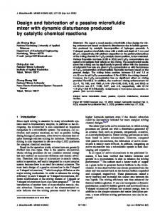
2. RELATED PRIOR WORK Recent years have seen growing interest in CAD tools for digital microfluidics [14-17]. One of the first published methods for biochip synthesis decouples high-level synthesis from physical design [15]. It is based on rough estimates for placement costs such as the areas of the microfluidic modules. These estimates provide lower bounds on the exact biochip area, since the overheads due to spare cells and cells used for droplet transportation are not known a priori. However, it cannot be accurately predicted if the biochip design meets system specifications, e.g., maximum allowable array area and upper limits on assay completion times, until both high-level synthesis and physical design are carried out. [18] proposed a unified system-level synthesis method for microfluidic biochips based on parallel recombinative simulated annealing (PRSA). Ground electrode
Top glass plate Droplet
Hydrophobic layer
Filler Fluid
Bottom plate
Control electrodes
(a) (b) Figure 2. An example to illustrate droplet interference due to the sharing of control pins by the electrodes: (a) coordinate locations for the electrodes; (b) pin-assignment for the electrodes.
(a) (b) Figure 1. A digital microfluidic array: (a) 2-D electrode array (b) unit cell side view. The top-down synthesis flow method unifies architecture level design with physical level module placement. Recent work on automated biochip design has also included post-synthesis droplet routing [19, 20]. These methods can reduce droplet transportation time by finding optimal routing plans for a synthesized biochip. Another important issue in biochip design is electrode addressing, i.e., the manner in which electrodes are connected to and controlled by input pins. Early design-automation techniques relied on the availability of a direct-addressing scheme. For large arrays, direct-addressing schemes leads to a large number of control pins, and the associated interconnect routing problem significantly adds to the product cost. A multiphase-bus based method has been proposed in [10]. Every nth electrode in an n-phase bus is electrically connected, where n is small number (typically n = 4). Thus, only n control pins are needed for a transport bus. Although the multi-phase bus method is useful for reducing the number of control pins, it is only applicable to a one-dimensional (linear) array.
Figure 3. An example of an inadvertent operation for a single droplet.
3.2 Minimum Number of Pins for a Single Droplet Given a two-dimensional microfluidic array, the problem of determining the minimum number of independent control pins, k, necessary to have full control of a single droplet (without interference) can be reduced to the well-known graph-coloring problem [21]. Full control implies that a droplet can be moved to any cell on the array through an appropriate electrode activation sequence. While the problem of finding the chromatic number of a graph is NP-Complete [22], it is trivial to observe that for rectangular arrays of size greater than 3×3, the largest number of directly adjacent neighbors to any cell is four. Hence, if k denotes the number of independent control pins, we ensure that k ≥ 5 such that each cell and all of its directly adjacent neighbors can be assigned different colors.
3. DROPLET-TRACE-BASED ARRAYPARTITIONING METHOD The key idea of pin-constrained design is to use a limited number of independent pins to control the electrodes in a digital microfluidic array. However, the sharing of control pins leads to the problem of droplet interference, which is defined as the inadvertent activation of multiple electrodes on which droplets are incident at any time instant. Droplet interference results in unintentional droplet operations caused by the simultaneous activation or deactivation of electrodes that are controlled by the same pin.
3.3 Pin Assignment for Multiple Droplets For multiple droplets, electrode interference can be solved by “virtually” partitioning the array into regions, with each of them having only one activated cell at any point in time.
191
Mutually-exclusive sets of pins are utilized for manipulating the droplets in different regions. The partitions can be viewed as subarrays that can contain at most one droplet. Recall that regardless of size, a two-dimensional array only needs five independent pins to ensure full control of a single droplet. By using different sets of five pins for electrode control in different partitions, electrode interference among partitions can be avoided. Therefore, for the partitioned array, the number of droplets that can be simultaneously transported without stall cycles is equal to the number of partitions, and the total number of control pins need is equal to five times the number of partitions. The above partitioning solution was proposed in [23]. We next describe an algorithm based on the concept of droplet trace, which unifies array partitioning and pin assignment.
To reduce the number of partitions, thereby reduce the number of control pins, a time-division pin-sharing (TDPS) method is introduced. The key idea is to merge partitions that have no overlapping time spans, defined by the period when there is droplet in it, which can be easily calculated from the scheduling result. Time span of the partitions derived from different droplet are checked in pairs. Partitions with non-overlapping time spans are merged, therefore reducing the number of partition by 1. Merging multiple partitions can be carried out by doing successive merging of two partitions. This check-merge procedure goes on until all partition pairs overlap in time span. We next investigate the cases when droplets traces intersect. This means partitions derived by the proposed method have spatial overlap. In this case, pin sets in the two overlapped partitions can not be used again in the overlapped region since it may cause electrode interference. Therefore, we make the overlapping region a new partition. Since there might be more than one droplets present in the new partition (cross region), we use direct-addressing scheme in it. Again, TDPS is utilized to reduce the pins number since pin sets of the other partitions whose time spans don’t overlap with that of the overlapping partition can be candidate for the direct- addressing in the overlapping partition.
3.4 Droplet-Trace-Based Partitioning Algorithm We first address the Partitioning Problem. As discussed above, electrode interference can be effectively avoided if only one droplet is included in each partition. Therefore, the partitioning criterion is to make sure at most one droplet is enclosed in each partition. However, partitions with no droplets (at any point in time) should be avoided because no droplet manipulation is done in this region with the additional set of pins assigned to it. Hence it is best to make partitions each with exactly one droplet enclosed. Droplet 1 Droplet 2
Detector 1(x,y) (8, 3) (3, 2)
Detector 2(x,y) (8, 9) (3, 6) (a)
Detector 3(x,y) (5, 9) (5, 6)
(a) (b) Figure 5. (a) Routing result and partitioning (b) Time-span table for the droplets. Table 1. Time-span table with detailed scheduling results for the overlapping region.
(b) Figure 4. (a) Detectors used in bioassay; (b) Routing result and array partitions. According to this requirement, we find that droplet movement trace, defined as all the cells traversed by a single droplet is a good tool to generate partitions. Recall that array partitioning and pin assignment is usually the last step in synthesis process, which means information of placement and routing result is available as a priori. Thus for each droplet, we can use its routing and placement information of the modules it is routed to pass to get the trace of it. A trace extraction example is shown in Figure 4. In Figure 4, two droplets are to be manipulated on the microfluidic array. The bioassay requires both of them to be detected by three optical sensors whose locations are specified in Figure 4. Droplet traces are derived based on the detector placement information as shown in Figure 4(b). For each droplet, we create a partition consisting of all the cells on its trace as well as the cells adjacent to them. The adjacent cells serve as a “guard ring” along the trace to avoid inadvertent mixing and movement. Note that in Figure 4(b) there are still two white regions that belong to neither partition. We call them “don’t care” regions because they are quite similar to the “don’t care” terms in the Boolean logic optimization. They can either be assigned to any partition or they can form an extra partition themselves if there are multi-droplet-operation modules, e.g. mixers, placed in them.
An example of this approach is shown in Figure 5. Droplet traces are first calculated from the routing result. Based on that, Partitions 1, 2, 3, and 4 are assigned. Partition 2 (yellow) and Partition 3(blue) overlap with each other in the green region. Thus a new Partition 23 is made. From the scheduling result in Figure 5(b), time span of Partition 23 is found to be 10s -- 14s. Then time spans of partitions 1 and 4 are checked and both of their time spans do not conflict with that of Partition 23. So the two sets of pins (2x5=10) in 1 and 4 can be used to directly address the 9 cells in Partition 23 independently. As shown in the above example, partitions sharing pins with the overlapping partition are empty while the droplets manipulation in the overlapping partition is operated. Therefore, though pins sharing will introduce electrode interference, as mentioned before, there are no droplets to be affected. By introducing the concept of TDPS, number of pins required for independent addressing is greatly reduced by pin sharing. This TDPS idea can also be applied in the spatial dimension to the droplet manipulations inside the overlapping region to further reduce the number of pins.
192
until the partition boundary is reached, a Bagua repetition is derived as shown in Figure 7. Bagua repetition form the basis of Connect-5 algorithm. It can be found that only five copies of Bagua repetitions are sufficient to cover partitions of any size. This is because of the property of the Bagua repetition that vertices connected to the same pin sharing appear exactly every five cells in the same row or column. A cover of the partition can be derived by simply take a Bagua repetition and shift it one cells to an arbitrary direction, e.g., upwards, then assign it with another pin and repeating this step this for four times, as shown in Figure 8. Note that, though the shifting direction is arbitrarily selected in the beginning of the algorithm, once chosen it must be consistent over the four shifting steps. As shown in Figure 8, pins assignment result derived by Bagua repetition shifting also displays a rigid cyclic property, i.e., each row is exactly a cyclic repetition of a ordered sequence and also a shifted copy (shift = 2 cells) of the previous row. This cyclic property provides a very easy way to implement the Connect-5 algorithm. To start, the first row of a partition is selected. Pins are assigned in a fixed cyclic order until the boundary of partition is reached. Then in the next row, the same order is used for assignment but with a 2-cell-shift to the left/right. The procedure goes on until all cells in the partition have been assigned pins. Recall that the shifting direction, once chosen, must be consistent in the whole assigning procedure within the same partition.
Once a spatial overlapping region is found, we check if different droplets in it overlap in temporal dimension. According to checking result, spatial overlapping regions can be divided into two groups, spatial overlapping temporal none-overlapping (SOTN) regions (group I) and spatial overlapping temporal overlapping (SOTO) regions (group II). For SOTO regions, direct-addressing is used, as what is done before; while for SOTN regions, though droplets traces intersects in spatial dimension, different droplets are manipulated one after another in time, i.e., at any time spot, there is at most one droplet inside the region. Therefore, a pin set of minimum size (k=5) for single droplet manipulation is enough for the partition without electrode interference. We next apply approach to the example in Figure 5. Table 1 shows the schedule information needed for carrying out the temporal check for the overlapping region. Partition 23.2 and 23.3 represent the manipulation of droplet 2 and 3 in partition23 respectively. Table 1 shows their time spans doesn’t overlap, thus 5 pins (in contrast to 9 pins for direct-addressing) is adequate for the overlapping partition.
3.5 Pin Assignment Using Connect-5 Algorithm The algorithm discussed in previous subsections offers an automated partitioning method for digital microfluidic biochip. Each partition is assigned a pin set. In this section, we go on to address the problem of how to assign control pins to the cells in a partition. An efficient and easy-to-implement algorithm will be given. The algorithm is based on a Chinese strategy of the “Connect-5” (Gomoku) game [24]. Thus it is referred to as Connect-5 algorithm. Pin set assigned to partitions in the above algorithm fall into two groups according to their cardinality, i.e., the minimum number of pins required for single droplet manipulation (k=5) and the number of pins required for direct-addressing. Here we focus on the pin assignment problem of the pin set in group I, since pin assignment for direct-addressing in group II is quite straight forward. The goal is to make sure every five adjacent cells (one central cell its 4 neighbors) that form a “cross” are assigned distinct pins. We refer to this constraint as “cross constraint”. Pin assignment problem under cross constraint can be converted to the famous vertex coloring problem in graph theory. The problem is to looking for a 5-coloring of the graph derived from a partition, as shown in Figure 6. Unit cells are in the partition are mapped to vertices and every two cells belonging to a “cross” is connected by an edge. The graph corresponds to a partition is referred to as partition graph.
Figure 7. Bagua structure (the tilt square) and its repetition in a square partition.
Figure 8. Assignment by shifting repetition along rows.
4. CROSS-REFERENCING-BASED DROPLET MANIPULATION METHOD In this section, we represent an alternative implementation of pin-constrained biochips. We propose a droplet manipulation method based on a “cross-referencing” addressing method that uses “row” and “columns” to access electrodes. By mapping the droplet movement problem to the clique partitioning problem from graph theory, the proposed method allows simultaneous movement of a large number of droplets on a microfluidic array. This in turn facilitates high-throughput applications on a pin-constrained biochip.
Figure 6. Example of mapping partition to mapping undirected graph The graph coloring problem, which involves the determination of the chromatic number χ(G) for a graph G, is known to be NP-complete [22]. However, if χ(G) or the number of colors to be used is known, as in the case here, there exists efficient algorithm for graph coloring. The well-arranged structure of the partitions can be used to solve the problem more efficiently using tiling. This approach allows us to use a regular distribution of pins, a layout feature that is not directly obtained from graph coloring. The tile used here is referred to as “Bagua”, a Chinese strategy for the Connect-5 game. The structure is defined as a tilt square as shown in Figure 7. By repeating Bagua structure one next to another
4.1 Cross-Referencing Addressing Pin-constrained lab-on-chip design based on “cross-referencing” addressing method was first proposed in [13]. This method allows control of an N×M grid array with only N+M control pins. The electrode rows are patterned on both the top and bottom plates, and placed orthogonally. In order to drive a droplet along the X-direction, electrode rows on the bottom plate serve as driving electrodes, while electrode rows on the top serve as reference ground electrodes. The
193
activated unintentionally when the activation voltage is applied to the row and column pins corresponding to the destination cells. As a result, Droplet 4 is unintentionally moved one cell up (along the Y-direction).
roles are reversed for movement along the Y-direction, as shown in Figure 9. This cross-reference method facilitates the reduction of control pins. However, due to electrode interference, this design cannot handle the simultaneous movement of more than two droplets. The resulting serialization of droplet movement is a drawback for high-throughput applications. The minimization of the assay completion time, i.e., the maximization of throughput, is essential for environmental monitoring applications where sensors can provide early warning. Real-time response is also necessary for surgery and neo-natal clinical diagnostics. Finally, biological samples are sensitive to the environment and to temperature variations, and it is difficult to maintain an optimal clinical or laboratory environment on chip. To ensure the integrity of assay results, it is therefore desirable to minimize the time that samples spend on-chip before assay results are obtained. Increased throughout also improves operational reliability. Long assay durations imply that high actuation voltages need to be maintained on some electrodes, which accelerate insulator degradation and dielectric breakdown, reducing the number of assays that can be performed on a chip during its lifetime.
4.2.2 Destination-Cell Categorization As shown in Figure 10, the concurrent manipulation of multiple droplets must be carried out without introducing any electrode interference. Here we propose a solution based on destination-cell categorization. Note that the problem highlighted in Figure 10 can be avoided if the destination cells of the droplets being moved simultaneously reside on the same column or row. However, electrode interference may still occur within the same column or row, as shown in Figure 11. L
F
L
F
F
2 Unintentional splitting
F
Destination cells
F
H
1
Y
Top electrode
X
F
V
F
X
Bottom electrode
Y
Suppose Droplet 1 and Droplet 2 are both moved one cell to the left at the same time. Even though no additional cells are activated unintentionally, Droplet 1 undergoes unintentional splitting in this situation. Fortunately, this problem can be avoided in practice by satisfying the fluidic constraints described in [20]. These constraints are given by the following set of inequalities: (i) |Pi(t)-Pj(t)| ≥ 2; (ii) |Pi(t+1)-Pj(t)| ≥ 2; (iii) |Pi(t)-Pj(t+1)| ≥ 2; (iv) |Pi(t+1)-Pj(t+1)| ≥ 2, where Pi(t) is the position of droplet i at time t and Pj(t) is the position of droplet i at time t. The fluidic constraints avoid unintentional fluidic operations that arise due to the overlapping of droplets over adjacent electrodes. Thus they apply to both direct-addressing-based and cross-referencing-based biochips. In Figure 11, the intended multiple droplet manipulation violates the constraint |Pi(t+1)-Pj(t)|≥2. If the fluidic constraints are satisfied at all times, it is safe to carry out concurrent manipulation of multiple droplets whose destination cells are accessed by the same column or row. On the basis of the above observations, we consider the droplets that can be moved simultaneously as part of the bioassay, and place them in different groups. A group consists of droplets whose destination cells share the same column or row. An example is shown in Figure 12.
Figure 9. Cross sections of a cross-referencing microfluidic device that uses single-layer driving electrodes on both top and bottom plates. FLFFHFLF
Destination cells FHFFLFHF
Unintentionally activated cells
4
1 2
3
Figure 11. An example of electrode interference within the same row.
Electrode Interference
Figure 10. An example to illustrate the problem of electrode interference. H/L stands for high/low voltage pairs to activate the cells, and unselected row/column pins are left floating (F).
4.2 Interference-Free Droplet Manipulation Based on Destination-Cell Categorization
1
10
In this section, we focus on the problem of manipulating multiple droplets on based digital microfluidic biochips that use cross-referencing to address the electrodes.
9
5
8
4.2.1 Droplet Interference
6
2
7
7
5 6
The droplet interference problem described in Section 3.1 also exists in cross-referencing-based biochip. For the concurrent manipulation of multiple droplets on a cross-referencing-based biochip, multiple row and column pins must be selected to activate the destination cells, i.e., cells to which the droplets are supposed to move. However, the selected row and column pins may also result in the activation of cells other than the intended droplet destinations. An example is shown in Figure 10. The goal here is to route Droplets 1, 2, 3 simultaneously to their destination cells. Droplet 4 is supposed to remain in its current location. However, two additional cells are
8
3
4
3
9
1
2
4 1
2
3
4
5
6
7
8
9
10
Figure 12: Example to illustrate destination-cell-based categorization.
194
10
6
9
5
5
7
7
8
3
9
8
4
9
1
1
2
4
2
3
3
4
3
4
5
5
6
6
7
7
6
2
8
8
2
an edge because the destination cells for these droplets are accessed using Column 3 in the array. Similarly, Nodes 4 and 9 are connected by an edge because the corresponding destination cells are addressed using the same row. A clique in a graph is defined as a complete subgraph, i.e., any two nodes in this subgraph are connected by an edge [21]. Clique partitioning refers to the problem of dividing the nodes into overlapping subsets such that the subgraph induced by each subset of nodes is a clique. A minimal clique partition is one that covers the nodes in the graph with a minimum number of non-overlapping cliques. The grouping of droplets as discussed above is equivalent to the clique partitioning problem. The categorization of destination cells using the grouping of droplets is equivalent to the problem of determining a minimal clique partition. Cliques of different sizes for a given droplet movement graph are shown in Figure 15. A minimal clique partition here is given by {1,2,3,4}, {5,6}, {7,8,9}, which corresponds to the groups derived in Section 4.2.2.4. Even though the general clique partitioning problem is known to be NP-hard [22], a number of heuristics are available in the literature to solve it in an efficient manner.
1
9
10
1
1
2
3
4
5
6
7
8
9
10
1
2
3
4
5
6
7
8
9
10
Figure 13: Example to illustrate the concurrent movement of a group of droplets. A total of nine droplets are needed to be moved on a 10×10 array. As discussed above, we group the droplet movements according to their destination cells. For example, Droplets 4 and 9 from a group since the destination cells in both cases resides on Row 2. Similarly Droplets 1, 2, and 3 are placed in the same group since they are all moving to Column 3. Following this grouping process, we finally get four groups of droplets, i.e., {4,9}, {1,2,3}, {5,6},{7,8}. In this way, the manipulation of multiple droplets is ordered in time; droplets in the same group can be moved simultaneously without electrode interference, but the movements for the different groups must be sequential. For example, droplet movements for the group {4,9} in Figure 12 can be carried simultaneously, as shown in Figure 13. Droplet movements are carried out one group after another until all the droplet movements are completed. Note that the ordering of droplet movements based only on the above grouping strategy can cause electrode interference and inadvertent mixing. However, manipulations of this type violate the fluidic constraint given by |Pi(t+1)-Pj(t+1)| ≥ 2. Therefore, such problems can be avoided if the grouping procedure incorporates the fluidic constraints. Although the grouping of droplets based on destination cells reduces the number of droplets that can be simultaneously moved, this approach provides more concurrency than the baseline method of moving one droplet at a time. Compared to direct-addressing, an order of magnitude reduction in the number of control pins is obtained. Simulation results show that there is only a small increase in the bioassay processing time compared to direct-addressing.
4.2.4 Algorithm for Droplet Grouping Next we outline a greedy algorithm to determine a (minimal) clique partition for the droplet movement graph (DMG). Details are presented in [REF]. The algorithm determines cliques for the DMG in an iterative manner. The largest clique is first determined and then nodes and edges corresponding to this clique are deleted form the graph. Next, the clique searching procedure is applied to the reduced graph. The algorithm terminates when all the nodes in the DMG have been deleted, i.e., an empty graph is obtained. The computational complexity of this problem for the DMG is linear in the number of rows/columns. Recall that the cliques can only be formed among nodes sharing the same row or column. Therefore, the largest clique can be determined the scanning the columns and rows of the array. Thus a maximum of only N+M iterations are needed for the droplet movement graph derived from an N×M array. Note that even though in each step of the above algorithm, the largest clique and the associated destination cells are deleted, the absence of the corresponding destination cells does not lead to any added complexity for droplet movement. This is because the droplet movements involving these destination cells are incorporated in the clique determined at this step. Therefore, when the algorithm terminates with an empty graph, all droplet movements have been processed without any electrode interference.
4.2.3 Graph-Theoretic Model and Clique Partitioning We have thus far introduced the basic idea of multiple droplet manipulations based on destination-cell categorization, and shown that the droplets in each group can be moved simultaneously. Assuming that each step takes constant processing time, the total completion time for a set of droplet movement operations is determined by the number of groups derived from the categorization of destination cells. Note however that the grouping need not be unique. For instance, in the example of Figure 12, we can form four groups, i.e., {4,9}, {1,2,3}, {5,6} and {7,8}. However, {1,2,3,4},{5,6},{7,8,9} is also a valid grouping of the droplets. The latter grouping is preferable because three groups allow more concurrency, and therefore lower bioassay completion time. The problem of finding the minimum number of groups can be directly mapped to the clique partitioning problem from graph theory [21]. To illustrate this mapping, we use the droplet manipulation problem defined in Figure 12. Based on the destinations of the droplets, an undirected graph, referred to as the droplet movement graph, is constructed for each time-step; see Figure 15. Each node in the droplet movement graph represents a droplet. An edge in the graph between a pair of nodes indicates that the destination cells for the two droplets either share a row or a column. For example, Nodes 1 and 2, which represent the Droplet 1 and Droplet 2, respectively, are connected by
1 2 3
4-node clique 5 3-node clique
6
7 8
4
2-node clique
9
Figure 14: Mapping destination cell layout to undirected graph
5. EVALUATION EXAMPLE: MULTIPLEXED BIOASSAYS In this section, we apply the proposed partition and pin-assignment algorithm and the cross-referencing-based method to a real-life
195
experiment of a multiplexed biochemical assay consisting of a glucose assay and a lactate assay based on colorimetric enzymatic reactions, which have been demonstrated in [10]. The digital microfluidic lab-on-chip contains a 15×15 microfluidic array, as shown in Figure 16. The schedule for the set of bioassays, if a fully-addressable array with 225 control pins is available, is listed in Table 2; One iteration of the multiplexed assays takes 25.8 seconds. The movement of droplets (including test droplets) is controlled using a 50 V actuation voltage with a switching frequency of 16 Hz. A depiction of the droplet paths for multiplexed glucose and lactase assays is illustrated in Figure 18.
Figure 17. Partitions and pin assignment for the multiplexed bioassay. Blank areas are don’t-care regions that can be either left unaddressed or combined with any partition.
Figure 18: Refined partition and pin assignment result, void pin included
Figure 15: A 15×15 array used for multiplexed bioassays. Nop
I1
S1
I2
S1
I3
S2
I4
S2
I5
R1
I6
R2
I7
R1
M1
M2
M3
M4
D1
D2
D3
D4
I8
We first apply the array-partitioning based algorithm to the array. When the algorithm starts, six partitions are first assigned to the four droplet trace of Reactant 1,2 and Sample 1,2, and the two traces of the mixed samples going to detector 1 and 2. Another 3 partitions are assigned to the three trace-overlapping regions respectively. As the algorithm goes on, time span overlapping is checked for the three spatial overlapping partitions (partition3, 4 and 5). Since there is no temporal overlapping of droplets manipulation in both partition 3 and 5, only 5 pins is needed each of them. Partition 4 is recognized as mixer, thus only 5 pins is needed. In the next step, time span overlapping is checked for all partitions pairs. The six partitions corresponding to four droplets traces and two detector paths merge into two partitions (partition 1 and 2). Finally, Connected-5 algorithm is applied and both partition and pin assignment result is shown in Figure 18. Note that void cell can also be viewed as a type of pin that can be used to in the “guard ring” of the partition without affecting the functionality, the assignment result can be further refined, as shown in Figure 19. We next apply the proposed cross-referencing-based method to the multiplexed assay. The numbers of pins needed for both the method are shown in Figure 20. As a baseline, the number of pins needed for direct addressing method is also presented. As we can see from Figure 20, only 25 out of the possible 225 control pins are necessary in the array-partitioning-based pin-assignment layout, i.e., 11.11%. The cross-referencing-based chip requires a slightly larger number of pins — 30 (15 column pins +15 row pins), which is 13.33% of the number of pins required in direct-addressing. We therefore see that both the array-partitioning-based and cross-referencing-based method achieve a significant reduction in the input bandwidth. Next we investigate the throughput of the pin-constrained chips designed using the two proposed methods. Note that the scheduling result in Table 2 is obtained for a direct-addressable chip. According to Table 2, one iteration of the multiplexed assays takes 25.8 seconds. The array-partitioning-based method follows the same schedule in Table 2. Therefore, it has the same throughput and bioassay completion time as the direct-addressable array. To obtain the bioassay completion time on the cross-referencing-based array, the proposed droplet manipulation
R2
Figure 16: Sequencing graph model for a multiplexed in-vitro diagnostics. S1, S2 are samples, R1, R2 are reagents, M1, M2, M3, M4 are mixing operations, and Nop is a dummy source node. Table 2: Bioassay schedule for a full-addressable array. Step/Time Elapsed (seconds)
Operation
Step 1 / 0
Sample 2 and reagent 2 start to move towards the mixer. Sample 2 and reagent 2 begin to mix together and turn around in the 2×3-array mixer. Sample1 and reagent 1 start to move towards the mixer. Sample 2 and reagent 2 continue the mixing. Sample 2 and reagent 2 finish the mixing and product 2 leaves the mixer to optical detection location 2. Sample 1 and reagent 1 begin to mix in the 2×3-array mixer. Sample 1 and reagent 1 finish the mixing and product 1 leaves the mixer to the optical detection location 1. Product 2 continues the absorbance detection. Product 2 finishes optical detection and leaves the array to the waste reservoir. Product 1 continues the absorbance detection. Product 1 finishes optical detection and leaves the array to the waste reservoir. One procedure of the multiplexed bioassays ends.
Step 2 / 0.8 Step 3 / 6.0 Step 4 / 6.8
Step 5 / 12.8
Step 6 / 19.8
Step 7 / 25.8
196
“cross-referencing” addressing method that uses “row” and “columns” to access electrodes in digital microfluidic arrays. By mapping the droplet movement problem to the clique partitioning problem from graph theory, the proposed method allows simultaneous movement of a large number of droplets. Results show that high throughput can be obtained using a small number of control pins.
method based on clique partitioning are applied. The droplet positions for the different time-steps that we consider here correspond to the succession of droplet positions obtained using the direct-addressing method. Note that the transition between two time-steps, which takes only one manipulation step for direct addressing, can sometimes be carried out in one time-step for the proposed cross-referencing-based method as well. No additional droplet manipulation steps are needed in such cases. For other cases, the proposed method decomposes a single droplet movement step, which is adequate for direct addressing, into a succession of steps determined using destination-cell-based categorization. The proposed droplet-manipulation method is applied to every time-step derived from the direct-addressing scheme, and results in a completion time of 29.2 seconds. Note that the completion time obtained using the proposed droplet manipulation method is slightly more than that for direct-addressing method. However, this increase in completion time is acceptable considering the significant reduction in input bandwidth.
ACKNOWLEDGEMENT We express our gratitude to William Hwang, Dr. Fei Su, Dr. Vamsee K. Pamula and Dr. Michael G. Pollack for contributions to this work. This research was supported in part by the National Science Foundation under grants IIS-0312352 and CCF-0541055. This paper is based on material published in [12] and [25].
REFERENCES [1]
Fair, R.B., et al. 2003. “Electrowetting-based on-chip sample processing for integrated microfluidics.” in Proc. of IEEE International Electron Devices Meeting (IEDM). pp. 32.5.132.5.4 [2] Verpoorte, E. and Rooij, N. F. D., 2003. “Microfluidics meets MEMS”, Proc. of IEEE, vol. 91, pp. 930-953. [3] Zeng, J. and Korsmeyer, T. 2004, “Principles of droplet electrohydrodynamics for lab-on-a-chip”, Lab on a Chip, vol. 4, issue, 44, pp. 265-277. [4] Schulte, T.H. et al., 2002, “Microfluidic technologies in clinical diagnostics.”, Clinica Chimica Acta, vol. 321, pp. 1-10. [5] Cho, S.K. et al., 2003, “Creating, transporting, cutting, and merging liquid droplets by electrowetting-based actuation for digital microfluidic circuits”, Journal of Microelectromechanical Systems, vol. 12, issue 1, pp. 70-80. [6] Chen, X., et al., 2007, “Continuous flow microfluidic device for cell separation, cell lysis and DNA purification”, Analytica Chimica Acta, vol. 584, pp. 237-243. [7] Pollack, M.G. et al. 2000, “Electrowetting-based actuation of liquid droplets for microfluidic applications”, Applied Physics Letters, vol. 77, issue 11, pp. 1725-1726. [8] Abdelgawad, M. and Wheeler, A.R. 2007, “Rapid Prototyping in Copper Substrates for Digital Microfluidics”, Advanced Material, vol. 19, pp. 133-137. [9] Paik, P. et al., 2003, “Rapid droplet mixers for digital microfluidic systems”, Lab on a Chip, vol. 3, issue 4, pp. 253-259. [10] Srinivasan, V. et al., 2004, “An integrated digital microfluidic lab-on-a-chip for clinical diagnostics on human physiological fluids” Lab on a Chip, vol. 4, issue 4, pp. 310-315. [11] Srinivasan, V. et al, 2003, “Clinical diagnostics on human whole blood, plasma, serum, urine, saliva, sweat, and tears on a digital microfluidic platform,” Proc. of µTAS. pp. 1287-1290. [12] Xu, T. et al., 2007, “Automated design of pin-constrained digital microfluidic biochips under droplet-interference constraints”, ACM J. Emerging Tech. Computing Sys., vol. 3, issue 3, pp. 14.1-14.22. [13] Fan, S.-K. et al., 2003, “Manipulation of multiple droplets on N×M grid by cross-reference EWOD driving scheme and pressure-contact packaging”, in IEEE MEMS Conference, pp. 694- 697. [14] Yuh, P.-H. et al., 2006, “Placement of digital microfluidic biochips using the T-tree formulation”, in Proc. Design Automation Conference, pp. 931- 934. [15] Fei, S. and Chakrabarty, K., 2004, “Architectural-level synthesis of digital microfluidics-based biochips”, in Proc. IEEE/ACM International Conference on Computer Aided Design, pp. 223- 228.
# of control pins required
250 Directly-addressable chip 200 150 100 Array-partitioning- Cross-referencingbased chip based chip
50 0
1
2 Defect occurence probability p
3
Fi gure 19: Comparison of number of control pins required by array-partitioning-based method and cross-referencing-based method. Bioassay completion time
35 30
DirectArray-partitioningaddressable chip based chip
Cross-referencingbased chip
25 20 15 10 5 0
1
2 Defect occurence probability p
3
Figure 20: Comparison of bioassay completion time required by array-partitioning-based method and cross-referencing-based method. From Figure 20 and Figure 21, we note that the array-partitioning-based method achieves both a smaller number of control pins and a shorter bioassay completion time than the cross-referencing-based method. However, the arraypartitioning-based chip design can be used for only one assay, while the cross-referencing-based design can carry out different assays on the same chip.
6. CONCLUSIONS We have reviewed efficient pin assignment algorithms for digital microfluidic lab-on-chip. The first method is based on the concept of droplet trace, which is calculated from scheduling and placement results from automated synthesis tools. An efficient pin assignment scheme based on Connect-5 algorithm is used to derive the actual pin layout. We have also described a droplet manipulation method for a
197
[16] Bazargan, K. et al., 2001, “Integrating scheduling and physical design into a coherent compilation cycle for reconfigurable computing architectures”, in Proc. DAC, pp. 635 - 640. [17] Dougherty, W.E. and Thomas, D.E., 2000, “Unifying behavioral synthesis and physical design”, in Proc. DAC, pp. 756 - 761. [18] Fei, S. and Chakrabarty, K., 2005, “Unified high-level synthesis and module placement for defect-tolerant microfluidic biochips”, in Proc. DAC, pp. 825 - 830. [19] Böhringer, K. F., 2006, “Modeling and controlling parallel tasks in droplet-based microfluidic systems”, in IEEE TCAD, vol. 25, pp. 329-339 [20] Fei, S. et al, 2006, “Droplet routing in the synthesis of digital microfluidic biochips”, in Proc. Design, Automation and Test in Europe (DATE) Conf., pp. 323 - 328.
[21] Gross, J. L. and Yellen, J. Graph Theory and Its Applications. 1999, Boca Raton, Fla.: CRC Press. 585. [22] Papadimitriou, C. H., Computational Complexity. 1993., MA: Addison Wesley. [23] Hwang, W. et al., 2006, “Automated design of pin-constrained digital microfluidic arrays for lab-on-a-chip applications”, in Proc. of DAC, pp. 925-930. [24] Connect5 strategies, www.springfrog.com/games/gomoku/ [25] Xu, T. and Chakrabarty, K., 2007, “A cross-referencing-based droplet manipulation method for high-throughput and pin-constrained digital microfluidic arrays”, in Proc. of Design, Automation & Test in Europe (DATE) Conference, pp. 552-557.
198