to perform modular multiplication in a high-radix carry-save number system, where a .... arithmetic gates (GAND, FAND, XORG, and XORF), and wide-function ...
AUTOMATIC GENERATION OF MODULAR MULTIPLIERS FOR FPGA APPLICATIONS
1
Automatic Generation of Modular Multipliers for FPGA Applications Jean-Luc Beuchat and Jean-Michel Muller, Senior Member, IEEE LIP Research Report No 2007–1 LIP/Ar´enaire, CNRS – INRIA – ENS Lyon – Universit´e Lyon 1
Abstract— Since redundant number systems allow constant time addition, they are often at the heart of modular multipliers designed for public key cryptography (PKC) applications. Indeed, PKC involves large operands (160 to 1024 bits) and several researchers proposed carry-save or borrow-save algorithms. However, these number systems do not take advantage of the dedicated carry logic available in modern Field Programmable Gate Arrays (FPGAs). To overcome this problem, we suggest to perform modular multiplication in a high-radix carry-save number system, where a sum bit of the carry-save representation is replaced by a sum word. Two digits are then added by means of a small Carry-Ripple Adder (CRA). Furthermore, we propose an algorithm which selects the best high-radix carry-save representation for a given modulus, and generates a synthesizable VHDL description of the operator.
I. I NTRODUCTION
T
HIS paper is devoted to the study of modular multiplication of large operands on Field Programmable Gate Arrays (FPGAs). This operation is crucial in many public key cryptosystems (e.g. elliptic curve cryptography, XTR, RSA) and various solutions have already been investigated. Since iterative algorithms allow a good trade-off between calculation time and circuit area, they have received considerable attention. Least significant digit first schemes are often based on Montgomery’s algorithm [1]. However, this approach requires pre- and post-processing and is of interest when a large amount of consecutive modular multiplications is required (e.g. modular exponentiation). In this paper, we will consider a most significant digit first scheme. In order to compute hXY iM = XY mod M , where M is an n-bit integer such that 2n−1 < M < 2n , our algorithm is described by an iterative procedure based on the celebrated Horner’s rule: hXY iM = h(. . . ((xr−1 Y )2 + xr−2 Y )2 + . . .)2 + x0 Y iM , where X is an unsigned r-bit integer and Y is an n-bit integer belonging to {0, . . . , M − 1}. This equation can be expressed recursively as follows: T [i] Q[i]
= 2Q[i + 1] + xi Y, = hT [i]iM ,
(1)
where Q[r] = 0 and Q[0] = hXY iM . Since Q[i + 1] and Y are less than or equal to M − 1, Q[i] < 3M and Jean-Luc Beuchat is with the University of Tsukuba, Japan. J.-M. Muller is with the CNRS, laboratoire LIP, projet Ar´enaire, France.
Equation (1) is implemented by means of a left shift, an addition, a comparator, and up to two subtractions to perform the modulo M reduction [2]. Since public key cryptography involves large integers, operands are often represented in the carry-save number system, which allows addition in constant time (see for instance [3]). However, due to the redundancy of this representation, comparison requires a conversion in a non-redundant number system. This operation involves carry propagations, thus losing the main advantage of the carry-save representation. Several improvements of the algorithm sketched by Equation (1) have therefore been investigated to avoid comparisons. They are based on the following observation: computing a number congruent with Q[i] modulo M only requires to inspect a few most significant digits of T [i]. Koc¸ and Hung proposed for instance a carry-save algorithm based on a sign estimation technique [4], [5]. At each step −M , 0, or M is added to T [i] according to a few most significant digits of Q[i + 1]. When the modulus M is known at design time, which is often the case in public key cryptography, another approach consists in building a table
� ψ(a) = a · 2β M and in defining the following iteration: T [i] = 2P [i + 1] + xi Y, P [i] = ψ(T [i] div 2β ) + hT [i]i2β ,
(2) (3)
where P [r] = 0 and β is generally chosen equal to n or n − 1. Since ψ(T [i] div 2β ) is an n-bit number, P [i] and T [i] are respectively (n + 1)- and (n + 3)-bit numbers. Therefore, the algorithm sketched by the above equations require a small table. Carry-save implementations of Equations (2) and (3) have for example been proposed by Jeong and Burleson [6], Kim and Sobelman [7], and Peeters et al. [8]. Takagi and Yajima investigated signed digit-based architectures [9], [10]. Since these algorithms depend on the modulus M , they seem likely candidates for cryptographic hardware based on FPGAs: the reconfigurability of these devices allows to optimize the architecture according to some parameters (e. g. the modulus) and to modify the hardware whenever they change. Modern FPGAs are mainly designed for digital signal processing applications involving rather small operands (16 to 32 bits). FPGA manufacturers chose to include dedicated carry logic allowing the implementation of fast carry-ripple adders (CRA) for such operand sizes. Let us study for example the architecture of a Spartan-3 device. Figure 1 describes the simplified architecture of a slice, which is the main logic resource for
2
AUTOMATIC GENERATION OF MODULAR MULTIPLIERS FOR FPGA APPLICATIONS COUT
CYSELG CYMUXG
of dedicated logic to describe a CSA leads to a larger operator (Table I). Similar problems arise for instance on all Virtex devices (Xilinx) and Cyclone II FPGAs (Altera). It is therefore interesting to investigate modular multiplication algorithms based on FPGA-friendly number systems.
YBMUX
1
YB
FXINA FXINB
FiMUX Fi XORG
GYMUX Y
4 A[4:1]
G[4:1] G1
D
G−LUT
G2
D CYOG
Q
YQ
TABLE I
FFY
A REA
AND NUMBER OF
STAGES
(S PARTAN -3 FPGA).
1 0
GAND
LUT S OF THREE CARRY- SAVE ITERATION
BY CYSELF
1
CYMUXF
XBMUX XB
Algorithm
F5MUX F5 XORF
Jeong and Burleson [6] Kim and Sobelman [7] Peeters et al. [8]
FXMUX X
4 A[4:1]
F[4:1] F1
D
F−LUT
F2
D CYOF
FAND
1 0
Q
XQ
FFX
CIN
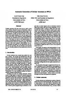
Simplified diagram of a slice of a Spartan-3 FPGA.
implementing synchronous and combinatorial circuits. Each slice embeds two 4-input function generators (G-LUT and F-LUT), two storage elements (FFY and FFX), carry logic (CYSELG, CYMUXG, CYSELF, CYMUXF, and CYINIT), arithmetic gates (GAND, FAND, XORG, and XORF), and wide-function multiplexers. Each function generator is implemented by means of a programmable look-up table (LUT). Recall that a full-adder (FA) cell has two bits xi and yi , as well as a carry-in bit cin as inputs, and computes a sum bit si and a carry-out bit cout such that 2cout + si = xi + yi + cin . Let hi = xi ⊕ yi . Then, a solution to this equation is given by: si cout
With carry logic n = 32 n = 64 119 slices 232 slices 141 LUTs 271 LUTs 93 slices 188 slices 123 LUTS 249 LUTs 95 slices 190 slices 95 LUTs 190 LUTs
CYINIT
BX
Fig. 1.
Without carry logic n = 32 n = 64 107 slices 210 slices 200 LUTs 392 LUTs 74 slices 166 slices 139 LUTs 268 LUTs 74 slices 160 slices 140 LUTs 271 LUTs
= hi ⊕ cin , ( xi if hi = 0 (i.e. xi = yi ), = cin otherwise.
(4) (5)
Assume that the F-LUT function generator computes hi . Then, the XORF gate implements Equation (4), whereas Equation (5) involves three multiplexers (CYOF, CYSELF, and CYMUXF). si is either sent to another slice (output X) or stored in a flip-flop (FFX). The G-LUT function generator allows to implement a second FA cell within the same slice, which thus embeds a 2-bit CRA. Unfortunately, a conventional carry-save adder (CSA) requires twice as much hardware resources: since each slice has a single input carry CIN, it is impossible to implement two FA cells with independent carry-in bits. Therefore, hardware design tools allocate two functions generators when they are provided with a VHDL description of Equations (4) and (5). It is of course possible to write a VHDL code which explicitly instantiates F-LUT, XORF, and CYMUXF. Note that G-LUT can only be used to implement the control unit or the ϕ(.) table. According to experiment results, G-LUT often remains unused. Though reducing the number of LUTs of the design, taking advantage
We proposed a family of radix-2 algorithms designed for FPGAs embedding 4-input LUTs and dedicated carry logic in [11]. Table II compares our iteration stage against three carry-save schemes. Since these results do not include the conversion from carry-save to unsigned integer which occurs at the end of each multiplication, both area and delay of carry-save operators are underestimated. According to this experiment, our approach is efficient for moduli up to 32 bits. Thus, the aim of this paper is to extend our work to larger moduli. In order to benefit from dedicated carry logic available in almost all FPGA families, we suggest to choose a high-radix carry-save number system, where each sum bit of the carrysave representation is replaced by a sum word (Section II). Such a number system allows the design of a modular multiplication algorithm based on small CRAs (Section III). The main originality of our approach is maybe to analyze the modulus M in order to select the most efficient high-radix carrysave representation and to automatically generate the VHDL description of the operator (Section IV). Experimental results validate the efficiency of the proposed modular multiplication scheme (Section V). A small part of this study has been presented in 2005 at the Asilomar conference [12]. TABLE II A REA AND DELAY OF CARRY- SAVE AND RADIX -2 ITERATION (S PARTAN -3 FPGA). Algorithm Jeong and Burleson [6] Kim and Sobelman [7] Peeters et al. [8] Beuchat and Muller [11]
n = 16 58 slices 9 ns 41 slices 8 ns 50 slices 8 ns 21 slices 12 ns
n = 32 127 slices 11 ns 79 slices 10 ns 86 slices 11 ns 40 slices 14 ns
STAGES
n = 64 236 slices 14 ns 150 slices 12 ns 163 slices 12 ns 80 slices 20 ns
II. H IGH -R ADIX C ARRY-S AVE N UMBERS A k-digit high-radix carry-save number X is denoted by �� � � �� (c) (s) (c) (s) X = (xk−1 , . . . , x0 ) = xk−1 , xk−1 , . . . , x0 , x0 ,
J.-L. BEUCHAT AND J.-M. MULLER
3
(s)
where the jth digit xj consists of an nj -bit sum word xj (c) (s) (c) and a carry bit xj such that xj = xj + xj 2nj . According to this definition, we have: X = x0 + x1 2n0 + x2 2n0 +n1 + . . . + xk−1 2n0 +...+nk−2 k−2 � Pi Pk−1 X � (c) (s) (s) (c) = x0 + xi + xi+1 2 j=0 ni + xk−1 2 j=0 ni . i=0
1
0
1
0
1
0
1
1
0
1
0
1
1
0
1
1
1
0
0
1
1
0
1
0
0
1
0
1
0
High−radix carry−save
0
0
0
0
High−radix carry−save
1 1
Unsigned binary number
0
0
1
0
0 1
0
1
0
1
1 0
0
1
1
0 1
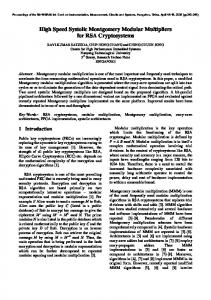
Fig. 2. Addition of an unsigned binary number and a high-radix carry-save number.
Let us define (s)
(s)
(s)
X (s) = x0 + x1 2n0 + . . . + xk−1 2n0 +...+nk−2 and X (c) =
(c) x0 2n0
+
(c) x1 2n0 +n1
+ ... +
(c) xk−1 2n0 +...+nk−1 .
With this notation, we have X = X (s) + X (c) . Such a number system has nice properties to deal with large numbers on FPGA: • its redundancy allows one to perform addition in constant time (the critical path only depends on max0≤j≤k−1 nj ); (s) (c) • the addition of a sum word xj , a carry bit xj−1 , and an nj -bit unsigned binary number can be performed by a CRA. A key observation is that all sum words do not need to have the same width. This peculiarity will allow us to select a number system according to the modulus to optimize our operators (Section IV). In the following, we will assume that the carry bit of the most significant digit is always equal to zero (the weight of the most significant carry bit is therefore equal to n0 + n1 + . . . + nk−2 ). Example 1 Figure 3a describes a 4-digit high-radix carrysave number with n0 = n1 = n2 = 4 and n3 = 3. According to the first definition of this number system, we have: � � � � (s) (c) (s) (c) (s) X = x0 + x0 + x1 · 24 + x1 + x2 · 28 + � � (c) (s) x2 + x3 · 212 = 10 + (1 + 4) · 24 + (0 + 3) · 28 + (1 + 7) · 212 = 33626. We can also compute X (s) = 10 + 4 · 24 + 3 · 28 + 7 · 212 = 29514 and X (c) = 1 · 24 + 0 · 28 + 1 · 212 = 4112. We obtain X = X (s) + X (c) = 33626.
a drawback in the sense that shifting an operand modifies its representation. The following example illustrates this problem, which occurs in the computation of T [i] (Equation (2)). Example 2 Let us consider again the number X = 33626, whose format is defined in Figure 3a. By shifting X, we obtain Z = 2X = 67252 (Figure 3b). However, the least significant sum word is now a 5-bit number and Z = z0 + z1 2n0 +1 + z2 2n0 +n1 +1 + z3 2n0 +n1 +n2 +1 = 20 + (1 + 4) · 25 + (0 + 3) · 29 + (1 + 7) · 213 = 67252. III. H IGH -R ADIX C ARRY-S AVE M ODULAR M ULTIPLICATION This section describes how to take advantage of a high-radix carry-save number system to perform a modular multiplication. In the following, we assume that: n−1 • The modulus M is an n-bit number belonging to {2 + 1, . . . , 2n − 1}. • X is an r-bit unsigned integer. • Y is an unsigned integer smaller than M . • At each iteration, a high-radix carry-save number P [i] congruent with 2P [i + 1] + xi Y modulo M is computed. We assume that P (c) [i] is smaller than 2n−α , where α is a small integer parameter. This constraint guarantees that: P [i + 1]
= P (s) [i + 1] div 2n−α D E + P (s) [i + 1] n−α + P (c) [i + 1] 2
The iteration of our algorithm is slightly different from the one described in Section I. Let us define k = P (s) [i + 1] div 2n−α and write the intermediate result at step i + 1 as follows: D E P [i + 1] = k2n−α + P (s) [i + 1] n−α + P (c) [i + 1] 2
Consider the modular multiplication described by Equations (2) and (3) and assume that both T [i] and P [i] are high-radix carry-save numbers. Each equation involves now the addition of a high-radix carry-save number and an unsigned integer (a partial product xi Y or a number ψ(T [i] div 2β ) stored in the table). Figure 2 describes how to perform these operations: the integer operand is split into k words of respective lengths n0 ,. . . , nk−1 ; then, each of these words is added to a sum word and a carry bit by means of an nj -bit CRA. The high-radix carry-save encoding has unfortunately
It is worth noticing that, according to our hypotheses, k2n−α and hP [i + 1]i2n−α are respectively an unsigned integer and a high-radix carry save number. In the following we will show that k is either a 3- or 4-bit number. Therefore, a small table addressed by k allows to efficiently compute a number congruent with P [i + 1] modulo M : D E
� P [i + 1] ≡ k2n−α M + P (s) [i + 1] n−α 2
+P (c) [i + 1]
(mod M ).
4
AUTOMATIC GENERATION OF MODULAR MULTIPLIERS FOR FPGA APPLICATIONS n 3= 3 Sum words
1
1
n 2= 4
1
(s)
0
1
1
0
1
(s)
x3 Carry bits
0
n 1= 4
(c)
1
0
1
0
x0
1
(c)
(c)
x1
n 2= 4
n 3= 3
(s)
x1
0
x2
0
(s)
x2
1
0
n 0= 4
x0
1
1
1
(s)
0
0
1
n 1= 4
1
1
(s)
z3
1 (c)
z2
0
0
(s)
z2
0
1
0
1
0
0
(s)
z1
z0
1
(c)
(c)
z1
(a) Fig. 3.
0
n 0= 5
z0
(b)
High-radix carry-save numbers. (a) Encoding of the number X = 33626. (b) Encoding of Z = 2X.
It is important to recall here that we compute a high-radix carry-save number congruent with XY modulo M . Therefore, a conversion and a final modulo M reduction are mandatory. In order to keep the hardware overhead as small as possible, we apply a trick proposed by Peeters et al. [8] in the case of a carry-save implementation. At each step, our algorithm computes:
� P [i] = xi Y + 2 k2n−α M �D E � +2 P (s) [i + 1] n−α + P (c) [i + 1] . 2
According to this equation, P [i] is always even when xi Y = 0. Thus, by performing an additional step with x−1 = 0, we obtain an even number P [−1] congruent with 2XY modulo M . Note that P [−1]/2 is smaller than or equal to P [0] and easy to compute (a right shift of one position involves only wiring). Furthermore, performing the final modulo M correction with P [−1]/2 requires less hardware resources. Let ( n0 +...+nk−2 n−1 n0 +ψmax < M, 1 if 2 −1+2 +...+2 2 (6) α= 2 otherwise, where
� ψmax = max i · 2n−1 M .
By shifting the high-radix carry-save number P [i + 1], we define a new internal representation for T [i] (Section II). The second step consists in adding 2 hk · 2n−α iM to T [i], and in converting the result to the format of P [i + 1]. Algorithm 1 High-radix carry-save modulo M multiplication Require: An n-bit modulus M such that 2n−1 < M < 2n , an r-bit number X ∈ N, Y ∈ {0, . . . , M − 1}, and a parameter α computed according to Equation (6). P [i] and T [i] are high-radix carry-save numbers. Ensure: P = hXY iM . 1: P[r] ← 0; 2: x−1 ← 0; 3: for i in r − 1 downto −1 do 4: k ← P (s) [i + 1] div 2n−α � ; � 5: T [i] ← 2 P (s) [i + 1] 2n−α + P (c) [i + 1] + xi Y ; 6: P [i] ← T [i] + 2 hk · 2n−α iM ; 7: end for 8: P ← P [−1]/2; 9: if P > M then 10: P ← P − M; 11: end if
0≤i≤7
Assume that the most significant sum word of P [i] contains at least five bits if α = 2 (i.e. nk−1 ≥ 5) and six bits otherwise1 . Then, Algorithm 1 returns hXY iM and satisfies the following properties: • At the end of the loop, P [−1]/2 is a high-radix carrysave number equal to hXY iM or hXY iM +M . The final modulo M reduction requires at most one subtraction. (s) • P [i] is an (n + 2)-bit number. Thus, if α = 1, the table is addressed by k = 3 bits and can be stored within the LUTs of a CRA on Spartan-3 and Virtex FPGAs [11]. When α = 2, k = 4 bits are required to perform the modulo M reduction. A proof of correctness of our algorithm is provided in Appendix. At each iteration, a new intermediate result P [i] is computed in two steps. Let P˜ [i + 1] be
a high-radix � carrysave number such that P˜ (s) [i + 1] = P (s) [i + 1] 2n−α and P˜ (c) [i + 1] = P (c) [i + 1]. We first carry out the sum of the partial product xi Y and 2P˜ [i + 1] by means of small CRAs: T [i] = 2P˜ [i + 1] + xi Y. 1 In some cases, the algorithm also works with a 5-bit most significant word when α = 1. See the proof in Appendix for details.
The main difficulty of the implementation arises from the left shift of the carry bits P (c) [i + 1]. Since T [i] has a different encoding, it is necessary to perform a conversion. We suggest to compute a high-radix carry-save number U [i] which has the same encoding as P [i + 1], and is equal to the sum of the carry bits of T [i] and the output of the table (i.e. 2 hk · 2n−α iM ). Therefore, we perform the following operations at each iteration of Algorithm 1: T [i] ← 2P˜ [i + 1] + xi Y,
� U [i] ← 2 k · 2n−α M + T (c) [i], P [i] ← U [i] + T
(s)
(7)
[i].
Example 3 Let n = 16, k = 4, and n0 = n1 = n2 = n3 = 4. The high-radix carry-save number T [i] contains three carry bits of respective weights 25 , 29 , and 213 (recall the constraint introduced in Section II: the carry bit of the most significant digit is always equal to zero). We split 2 hk · 2n−α iM into four 4-bit words and perform three additions to compute U [i] (Figure 4).
J.-L. BEUCHAT AND J.-M. MULLER n 3= 4
1
0
1
n 2= 4
0
1
1
1
1 (c)
1
0
0
1
0
0
(c)
0
(s)
0
0
0
(c)
0
1
0
three bits to perform the modulo M reduction (α = 1): 0
2 k2 n−α M T (c)[i]
(c)
0
(s)
u2
1
t0
1
0
1
1
(s)
u2
1
n 0= 4
1
t1
u3
Fig. 4.
n 1= 4
1
t2
1
5
(c)
u1
1
0
0
U(s) [i]
(s)
u1
0
0
u0
0
U(c) [i]
(c)
u0
� Conversion of T [i] by merging its carry bits with 2 k · 2n−α M .
IV. C HOICE OF A H IGH -R ADIX C ARRY-S AVE N UMBER S YSTEM
Lets us represent the table involved in the modulo M correction by a matrix ΨM . It is worth noticing that the amount of hardware required to compute U [i] depends on the modulus M and the encoding of P [i]. For instance, if a column of ΨM contains only zeroes, it can be replaced by a carry bit at no extra cost. We propose an algorithm which selects a high-radix carry-save number system minimizing the hardware overhead introduced by the computation of Q[i] (Equation (7)). The basic idea of our algorithm consists in computing, for each column of the matrix, the cost of the addition of a carry bit. We build a directed acyclic graph as follows: • •
•
Since we want to perform a modular multiplication by means of small CRAs, we have to provide the algorithm with a constraint on the maximal number of positions wmax between two consecutive carry bits (without this constraint, we would for instance have an edge from first node to last node). The minimal distance between to consecutive carry wmin is set to two. It guarantees that the smallest building block is a 2-bit CRA.
In order to explain how to build the graph, we consider the 16-bit modulus M = 54107 and assume that wmax is equal to four bits. This modulus requires a table addressed by only
0 0 0 0 1 0 0 0
0 0 1 1 0 0 0 1
0 0 0 0 1 0 0 1
0 0 1 1 1 0 0 0
0 0 1 1 0 1 1 0
0 0 0 0 0 0 0 1
0 0 0 0 1 1 1 0
0 0 1 1 0 1 1 1
0 0 0 0 1 1 1 0
0 0 1 1 0 1 1 0
0 0 0 0 0 0 0 1
0 0 0 0 1 1 1 0
0 0 1 1 0 1 1 1
0 0 0 0 1 1 1 0
0 0 1 1 0 1 1 0
Each line� of the ΨM matrix contains a number ψk =
k · 2n−1 M . The rightmost column of ΨM stores for instance the least significant bits of the ψk ’s and we will number the columns from right to left in the following. (c) The cost of the addition of a carry bit tk depends on the (c) location of the next carry bit tk+1 . Assume that we combine (c) the third column of ΨM with t0 and recall that we do not allow carry bits in consecutive columns. Since each sum word is at most a 4-bit number in this example, we have to investigate the three following cases: (c) • Addition of t1 to the seventh column of ΨM (Figure 5). (5:3) Let us define ΨM as the matrix constituted of the third, fourth, and fifth columns of ΨM : 0 0 0 0 0 0 0 0 1 � � 0 0 1 (5:3) (5:3) ΨM = ψi = 0 1 0 , 0 1 1 0 1 1 1 0 1
Each node represents a column of the matrix ΨM . Assume that we want to merge a first carry bit with the ith column, and a second one with the jth column (j > i). The edge between nodes i and j encodes the amount of hardware involved in this operation.
A shortest path of this graph defines the high-radix carry-save representation minimizing the hardware overhead introduced by the computation of U [i] for a given modulus M . The algorithm requires two parameters to control the size of the CRAs: •
ΨM = 0 1 0 1 0 0 1 0
(5:3)
•
(5:3)
where ψi denotes the ith line of ΨM . Since the sum (c) (5:3) (c) of tk and ψi belongs to {0, . . . , 6}, we can add tk by means of three half-adder (HA) cells. Note that the third HA could be replaced by an OR gate. However, since we deal with FPGAs embedding dedicated carry logic, it is more efficient to describe a 3-bit adder in the VHDL code: the critical path includes a 3-bit CRA, whereas it would consist of a 2-bit CRA and a LUT with the other architecture. (c) Addition of t1 to the sixth column of ΨM (Figure 6). (c) (5:3) The addition of tk and ψi is again carried out by means of a 3-bit CRA. Computing the cost of this operation is however somewhat more difficult in this case. Recall that we have to modify the number system while merging the carry bits of T [i] with the table. Adding carry bits to the third and sixth columns of the matrix means (c) (c) that the weights of t0 [i] and t1 [i] are respectively 3 6 equal to 2 and 2 (according to Equation (7), the selected line of ΨM is multiplied by two prior to its addition to T [i]). Thus, the first and second sum words of P [i] are respectively 2-bit and 3-bit numbers (Figure 7). Consider now the computation of the third digit of P [i]. This operation requires the fifth column of the modified (c) table, which depends on t0 . This carry bit is therefore
6
AUTOMATIC GENERATION OF MODULAR MULTIPLIERS FOR FPGA APPLICATIONS
FA
p(s) 7 [i]
(s) p(c) 1 [i] p6 [i]
Sum word
FA
FA
FA
p(s) 5 [i]
p(s) 4 [i]
p(s) 3 [i]
Carry bit
0 0 1 1 0 1 1 1
26
Addition of
23
22
(s) (s) (s) (s) p(s) [i] p(s) p(s) 3 [i] p2 [i] p1 [i] p0 [i] 6 [i] p5 [i] 4
P[i]
3rd sum word p(c) 1
to the seventh column of ΨM .
2nd sum word
[i]
2nd carry bit
HA
p(s) 6 [i]
p(s) 5 [i]
Sum word 3rd digit of P[i]
1st carry bit
(c)
3 bits
HA Generation
Sum word
t (s) 3 [i]
t (s) 4 [i]
t (s) 5 [i]
p(s) 3 [i]
FA
FA
p(s) 5 [i]
p(s) 4 [i]
FA (s) p(c) 1 [i] p3 [i]
Sum word
2nd digit of P[i]
Carry bit
3rd digit of P[i] Fig. 6.
Sum word
2nd digit of P[i]
(c)
Addition of tk+1 to the sixth column of ΨM (1). Fig. 8.
(c)
Addition of tk+1 to the fifth column of ΨM (1).
(c)
Addition of t1 to the fifth column of ΨM (Figure 8). (c) Since a 3-bit CRA is required to add t0 to the table, it seems impossible to deal with a carry bit in the fifth column. However, the weight of the second carry bit of P [i] is equal to 24 (Figure 9). We suggest to add a bit (c) of the third column of ΨM and t0 by means of a single HA cell and to generate a carry bit of weight 24 . This one is then treated as an input carry of the CRA computing the third sum word of P [i]. When the number of columns (c) (c) between two consecutive carry bits tk and tk+1 is not sufficient, we tag the edge with a flag g informing that (c) the addition of tk to the table generates a carry bit. This situation also arises if we consider the seventh and tenth columns. By applying these rules, we build the graph depicted on Figure 11. An additional difficulty is introduced by the constraint on nk−1 (Section III). Since we assume that nk−1 ≥ 6 when α = 1, the weight of the most significant carry bit must be •
0 0 1 1 0 1 1 1
t (c) 0 [i]
0 0 0 0 1 1 1 0
of a carry bit
FA
(s) p(c) 1 [i] p4 [i]
0 0 0 0 0 0 0 1
HA
HA
FA
Carry bit
0 0 1 1 0 1 1 1
[i]
Addition of tk+1 to the sixth column of ΨM (2).
t (c) 1 [i]
t (c) 0 [i]
HA t (s) 4 [i]
t (s) 5 [i]
HA
0 0 0 0 1 1 1 0
t (s) [i] 3
t (c) 1 [i]
HA
t (s) 6 [i]
HA
3 bits
1st sum word
p(c) 0
propagated through a second CRA. In order to include this information in the cost, we define a flag p: in this example, the edge will be labeled 3p.
0 0 0 0 0 0 0 1
20
6th 5th 4th 3rd 2nd 1st column column column column column column
Table
Fig. 7.
0 0 1 1 0 1 1 0
21
t (c) [i] 0
t (c) 1 [i]
2nd digit of P[i] (c) tk+1
24
T[i]
Sum word
3rd digit of P[i]
25
(s) (s) (s) (s) (s) (s) t (s) 6 [i] t 5 [i] t 4 [i] t 3 [i] t 2 [i] t 1 [i] t 0 [i]
HA
t (s) 4 [i]
HA
t (s) [i] 5
t (s) 6 [i]
HA
Fig. 5.
0 0 0 0 1 1 1 0
HA
t (s) 7 [i]
HA
0 0 0 0 0 0 0 1
t (c) 0 [i]
t (c) 1 [i]
0 0 1 1 0 1 1 0
t (s) 3 [i]
3 bits
0 0 0 0 1 1 1 0
26
25
24
23
22
21
20
(s) (s) (s) (s) (s) (s) t (s) 6 [i] t 5 [i] t 4 [i] t 3 [i] t 2 [i] t 1 [i] t 0 [i]
T[i] t (c) [i] 0
t (c) 1 [i] Table
6th 5th 4th 3rd 2nd 1st column column column column column column (s) (s) (s) (s) p(s) [i] p(s) [i] p(s) 4 [i] p3 [i] p2 [i] p1 [i] p0 [i] 6 5
P[i]
2nd sum word
3rd sum word p(c) 1
[i]
2nd carry bit Fig. 9.
(c)
p(c) 0
[i]
1st carry bit
Addition of tk+1 to the fifth column of ΨM (2).
1st sum word
J.-L. BEUCHAT AND J.-M. MULLER
7
smaller than or equal to 2n−3 (Figure 10) to guarantee the correctness of the algorithm. However, in this example, this constraint can be relaxed (see Appendix B): the algorithm works if nk−1 ≥ 4. Note that there is no edge between nodes 12 and 14: this would imply a carry bit of weight 216 and nk−1 would be equal to three.
213
29
25 T (s)[i] T (c)[i] 0 0
2n−3 2P (s)[i+1]
0
U(c) [i]
6 bits
P (s) [i]
n k−1
2P (c)[i+1]
P (c)[i]
T (s)[i]
6 bits
T (c)[i]
n bits
.
The next step consists in finding a shortest path in the graph. In order to minimize the critical path, it is interesting to avoid carry generations and propagations. Therefore, we prune all edges with a p or g flag and try to find a solution (Figure 12). For the moduli considered in this example, we obtain the description of a high-radix carry-save representation: T (c) [i] contains three carry bits of respective weights 25 , 29 , and 213 (Figure 13). Thus, P [i] is a 4-digit word with n0 = n1 = n2 = 4 and n3 = 6. Let us check that this encoding satisfies Equation (6). Since n = 16 and ψmax = (1010110010100101)2 = 44197, we have 2n−1 − 1 + 2n0 + 2n0 +n1 + 2n0 +n1 +n2 + ψmax 2 215 + 24 + 28 + 212 + 44197 = = 40666 < M. 2 Therefore, α = 1 is a valid choice. If the pruned graph does not contain a path from node 1 to node n, we have to consider the full graph. In some cases, there is no solution for α = 1 and we have to build a new matrix ΨM for α = 2. The description of the number system allows to automatically generate a VHDL description of the operator. Further optimizations are possible in some cases. Consider the 16-bit modulus M = 65295 and its ΨM matrix for α = 1: 0 0 0 0 0 0 0 0
0 0 0 0 0 0 0 0
0 0 0 0 0 0 0 0
0 0 0 0 0 0 0 0
0 0 0 0 0 0 0 0
0 0 0 0 0 0 1 1
0 0 0 0 1 1 0 0
0 0 1 1 1 1 1 1
0 0 1 1 1 1 1 1
0 0 1 1 1 1 0 0
4 bits
4 bits
Fig. 13. Choice of a high-radix carry-save representation for the 16-bit modulus M = 54107 (3).
n+2 bits
ΨM = 0 1 0 1 0 1 0 1
4 bits
2 k2 n−α M
0
Fig. 10.
2 k2 n−α M U(s) [i]
0 0 1 1 0 0 1 1
0 0 0 0 0 0 0 0
0 0 0 0 0 0 0 0
0 0 0 0 1 1 1 1
0 0 1 1 0 0 1 1
Several columns are null and we can replace them by a carry bit. Edges originating from the corresponding nodes in the (i+j:i) graph have therefore a null cost. Assume that ΨM contains identical columns (in the above example, columns 7 and 8 are (c) the same) and that we add a carry bit tl [i] to the ith column. We obtain a (j + 2)-bit word v defined as follows: (i:i)
v0 = ψk
(i:i) ¯(c) tl [i], (i:i) (c) ψk tl [i],
vh = ψk vj+1 =
(c)
⊕ tl [i], 1 ≤ h ≤ j,
(i:i)
where ψk denotes the k-th line of the ith column of ΨM . Therefore, the sum is computed by means of three LUTs and this operation does not involve any carry propagation. We therefore add a single LUT on the critical path and the cost is equal to one. V. I MPLEMENTATION R ESULTS In order to compare our algorithm against modular multipliers published in the open literature, we wrote a VHDL code generator whose inputs are a modulus M and wmax (maximal number of positions between two consecutive carry bits, see Section IV). Our tool returns a structural VHDL description of a high-radix carry-save multiplier, as well as scripts to automatically place-and-route the design and collect area and timing informations. This tool also generates a VHDL description of two architectures proposed by other researchers. The first one, described by Peeters et al. in [8], is summarized by Algorithm 2. Intermediate results are carrysave numbers denoted by (C[i], S[i]). At each step, a CRA computes the sum k of the three most significant bits of C[i + 1] and S[i�+ 1]. This four-bit word addresses a table storing k · 2n−2 M , 0 ≤ k ≤ 15. Thanks to an additional iteration with x−1 = 0, this algorithms returns a carry-save number number (C[−1], S[−1]) which is smaller than 2M . Since our multiplier satisfies the same property, conversion in a non-redundant number system is performed with the same
8
AUTOMATIC GENERATION OF MODULAR MULTIPLIERS FOR FPGA APPLICATIONS
2 FAs
16
2 FAs
14
1 FA g
12
3 FAs g
3 FAs
2 FAs p
10
1 FA g
8
4 FAs p
2 FAs
1 FA g
6
2 FAs p
4
1 FA g
2 0 0
1 FA
3 FAs
3 FAs
3 FAs p
2 FAs
2 FAs
3 FAs p
2 FAs g
2 FAs g
2 FAs
2 FAs
3 FAs p
2 FAs g
1 0 0
15
1 FA g
13
1 FA g
11
2 FAs p
2 FAs
Fig. 11.
9
1 FA g
4 FAs p
7
2 FAs
1 FA g
5
1 FA g
3
3 FAs
Choice of a high-radix carry-save representation for the 16-bit modulus M = 54107 (1). 3 FAs
16
12
2 FAs
8
4 0
1 FA
3 FAs
3 FAs
2 FAs
1
2 FAs 0
15
13
9
2 FAs
Fig. 12.
5
2 FAs
Choice of a high-radix carry-save representation for the 16-bit modulus M = 54107 (2). Shaded nodes belong to the shortest path.
operator2 . We will therefore only consider iteration stages in our experiments in order to compare high-radix carry-save and carry-save number systems. Algorithm 2 Peeters et al.’s modulo M multiplication [8]. Require: An n-bit modulus M such that 2n−1 < M < 2n , an r-bit number X ∈ N, and Y ∈ {0, . . . , M − 1}. We assume that x−1 = 0. Ensure: P = hXY iM . C[r] ← 0; S[r] ← 0; for i in r − 1 downto −1 do k ← C[i + 1] div 2n−2 + �S[i + 1] div 2n−2 ; T [i] ← xi Y + 2 k · 2n−2 M ; (C[i], S[i]) ← 2(hC[i + 1]i2n−2 + hS[i + 1]i2n−2 ) + T [i]; end for P ← (S[−1] + C[−1])/2; if P > M then P ← P − M; end if Amanor et al. introduced a carry-save architecture optimized for modular multiplication on FPGAs in [13]. The authors assume that both M and Y are known at design 2 Our approach further reduces the wiring since high-radix carry-save numbers involve less carry bits than carry-save numbers.
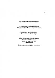
time. This hypothesis allows the design of an iteration stage embedding a single CSA and a table addressed by the most significant bit of xi , C[i+1], and S[i+1] (Algorithm 3). They show that the sum of the most significant bits of C[i + 1] and S[i + 1] is always a two-bit number. Therefore the table only contains eight values. Unfortunately, the authors did not address the final conversion issue. However, since C[i + 1] div 2n−1 + S[i + 1] div 2n−1 ≤ 3, we deduce that: C[i] + S[i] = (C[i + 1] div 2n−1 + S[i + 1] div 2n−1 ) · 2n−1 + hC[i + 1]i2n−1 + hS[i + 1]i2n−1 ≤ 3 · 2n−1 + 2 · (2n−1 − 1) = 2n+1 + 2n−1 − 2. Since M belongs to {2n−1 + 1, . . . , 2n − 1}, C[i] + S[i] may be greater than 2M and Algorithm 3 requires more hardware resources than our algorithm or Peeters et al.’s scheme to perform a conversion. Figure 14 describes place-and-route results on a Xilinx Spartan-3 FPGA. In these experiments, the moduli are 256-bit randomly generated primes. Compared against Algorithm 2, we observe that: • Our high-radix carry-save architecture allows to significantly reduce the number of slices, while only slightly augmenting the critical path. Increasing the parameter wmax allows to further diminish the area, at the price of a longer critical path. Note that conversion from (high-
J.-L. BEUCHAT AND J.-M. MULLER
Algorithm proposed by Peeters at al. [8];
650
24
600
22
550
20 Delay [ns]
Area [slices]
Proposed algorithm;
9
500 450
18 16
400
14
350
12
300
Algorithm proposed by Amanor et al. [13].
10 0
5
10
15
20
25 30 Experiment
35
40
45
50
0
5
10
15
20
25 30 Experiment
35
40
45
50
35
40
45
50
35
40
45
50
35
40
45
50
(a) Area and delay comparisons for n = 256 and wmax = 8 700
24
650
22 20
550 Delay [ns]
Area [slices]
600
500
18 16
450 14
400
12
350 300
10 0
5
10
15
20
25 30 Experiment
35
40
45
50
0
5
10
15
20
25 30 Experiment
(b) Area and delay comparisons for n = 256 and wmax = 16 700
24
650
22
600 20 Delay [ns]
Area [slices]
550 500 450
18 16
400 14 350 12
300 250
10 0
5
10
15
20
25 30 Experiment
35
40
45
50
0
5
10
15
20
25 30 Experiment
(c) Area and delay comparisons for n = 256 and wmax = 24 700
24
650
22
600 20 Delay [ns]
Area [slices]
550 500 450
18 16
400 14 350 12
300 250
10 0
5
10
15
20
25 30 Experiment
35
40
45
50
0
5
10
15
20
25 30 Experiment
(d) Area and delay comparisons for n = 256 and wmax = 32 Fig. 14.
Area and delay of modular multipliers on a Spartan-3 FPGA. 50 prime moduli were randomly generated for each experiment.
10
AUTOMATIC GENERATION OF MODULAR MULTIPLIERS FOR FPGA APPLICATIONS
Algorithm 3 Amanor et al.’s modulo M multiplication [13]. Require: An n-bit modulus M such that 2n−1 < M < 2n , an r-bit number X ∈ N, and Y ∈ N. Ensure: P = hXY iM . C[r] ← 0; S[r] ← 0; for i in r − 1 downto 0 do k ← 2(C[i 1] div 2n−1� + S[i + 1] div 2n−1 );
+n−1 T [i] ← k · 2 + xi Y M ; (C[i], S[i]) ← 2(hC[i + 1]i2n−1 + hS[i + 1]i2n−1 ) + T [i]; end for P ← hC[0] + S[0]iM ;
•
radix) carry-save to unsigned binary integer is usually based on pipelined CRAs (see for instance [3]). Depending on the trade-off between area and delay, this operator can be slower than an iteration stage based on (highradix) carry-save arithmetic. The area of our operator is less sensitive to the choice of M . This is mainly related to the architecture of Xilinx FPGAs: in most cases, α = 1 (see Equation (6)) and each operator embeds a table addressed by three bits. Since our target FPGA embeds four-input LUTs, this table is embedded within the slices of the adder computing P [i] [11]. Since four bits address the table of Algorithm 2, additional LUTs are requested. Their amount depends on the modulus M : if ψM contains null or identical columns, synthesis tools are able to simplify the design.
For the moduli considered in these experiments, high-radix carry-save multipliers have roughly the same area as the operator proposed by Amanor et al.. Recall that a CSA requires twice the number of slices of a CRA on our target FPGA family. Since moduli involved in these experiments require only three bits to perform a modulo M reduction, our architecture is mainly based on two CRAs. High-radix carrysave representations allow here to design a more versatile modular multiplier (both X and Y are inputs) with the same number of slices. Table III summarizes further results obtained with a Spartan3 FPGA. We generated 100 prime moduli for each experiment and measured the area and delay ratios between our proposal and Algorithms 2 and 3. These experiments indicate that our approach always allow to select a prime number for which reduces the circuit area without increasing the critical path. Table IV digests experiment results involving an Altera Cyclone II FPGA. Figure 15 describes a Logic Element (LE), which is the smallest unit of configurable logic in the Cyclone II architecture. Each LE includes a four-input LUT, a storage element, as well as dedicated carry logic, and operates in normal mode or arithmetic mode. CRAs are based on LEs in arithmetic mode, in which the LUT implements two three-input function generators. It is therefore impossible to store ψM within LUTs of a CRA. This explains why our algorithm leads to slightly smaller area savings for this FPGA family. On Cyclone-II devices, CSA operators are significantly faster; however, conversion to a non-redundant number system involves pipelined CRAs. If this operator is based on 32-
Register Chain Routing From Previous LE LAB Carry−In
data1 data2 data3
Look−Up Table (LUT)
data4
Synchronous Load and Clear Logic
Carry Chain
D
ENA CLRN
LAB Carry−Out
Q
Row, Column, And Direct Link Routing
Row, Column, And Direct Link Routing Local Routing Register Chain Output
data1 data2
LAB Carry−In
Three−Input LUT
Sum Bit
Three−Input LUT
LAB Carry−Out
Fig. 15. Simplified diagram of a LE in arithmetic mode (Cyclone II family).
bit blocks, our high-radix carry-save iteration stage has a slower critical path. In this case, our approach leads to smaller modular multipliers than CSA schemes, without impacting on computation time. VI. C ONCLUSION We proposed an algorithm to automatically generate VHDL descriptions of modular multipliers for FPGAs. The main originality of our approach is the selection of an optimal highradix carry-save encoding of intermediate results according to a given modulus M . High-radix carry-save number systems take advantage of dedicated carry logic available in almost all FPGA families and reduce the amount of interconnects. Therefore, our approach allows to significantly reduce the area of modular multipliers. ACKNOWLEDGMENT The work described in this paper has been supported in part by the New Energy and Industrial Technology Development Organization (NEDO), Japan, and by the Swiss National Science Foundation through the Advanced Researchers program ´ while Jean-Luc Beuchat was at Ecole Normale Sup´erieure de Lyon (grant PA002–101386). The authors would like to thank F. de Dinechin et J. Detrey for administrating the CAD tool servers on which experiments described in this paper were performed. R EFERENCES [1] P. Montgomery, “Modular multiplication without trial division,” Mathematics of Computation, vol. 44, no. 170, pp. 519–521, 1985. [2] G. R. Blakley, “A computer algorithm for calculating the product ab modulo m,” IEEE Trans. Comput., vol. C–32, no. 5, pp. 497–500, 1983. [3] M. D. Ercegovac and T. Lang, Digital Arithmetic. Morgan Kaufmann, 2004. [4] C. K. Koc¸ and C. Y. Hung, “Carry-save adders for computing the product AB modulo N,” Electronics Letters, vol. 26, no. 13, pp. 899–900, June 1990. [5] ——, “A fast algorithm for modular reduction,” IEE Proceedings: Computers and Digital Techniques, vol. 145, no. 4, pp. 265–271, July 1998. [6] Y.-J. Jeong and W. P. Burleson, “VLSI array algorithms and architectures for RSA modular multiplication,” IEEE Trans. VLSI Syst., vol. 5, no. 2, pp. 211–217, June 1997.
J.-L. BEUCHAT AND J.-M. MULLER
11
TABLE III A REA AND DELAY OF MODULAR
N 64
128
160
192
256
A REA AND DELAY OF MODULAR
N 64 128
MULTIPLIERS ON A
S PARTAN -3 FPGA. 100 PRIME MODULI Peeters et al. [8]
WERE RANDOMLY GENERATED FOR EACH EXPERIMENT.
Amanor et al. [13]
wmax
Area of Algorithm 1 Area of Algorithm 2
Delay of Algorithm 1 Delay of Algorithm 2
Area of Algorithm 1 Area of Algorithm 3
Delay of Algorithm 1 Delay of Algorithm 3
8 16 8 16 32 48 8 16 32 48 8 16 24 32 8 16 24 32
[0.45, 0.68] [0.39, 0.58] [0.48, 0.68] [0.44, 0.55] [0.43, 0.53] [0.40, 0.50] [0.51, 0.64] [0.48, 0.56] [0.44, 0.53] [0.36, 0.52] [0.53, 0.63] [0.48, 0.55] [0.46, 0.53] [0.46, 0.52] [0.54, 0.63] [0.49, 0.55] [0.48, 0.53] [0.47, 0.53]
[0.89, 1.45] [0.97, 1.49] [0.99, 1.32] [0.99, 1.32] [1.00, 1.44] [1.04, 1.69] [0.98, 1.15] [0.99, 1.19] [1.04, 1.36] [1.11, 1.56] [0.57, 1.38] [0.62, 1.47] [0.55, 1.49] [0.65, 1.46] [0.89, 1.48] [0.94, 1.45] [0.99, 1.59] [1.01, 1.68]
[0.77, 1.12] [0.73, 0.97] [0.89, 1.28] [0.79, 0.96] [0.77, 0.91] [0.74, 0.89] [0.90, 1.09] [0.84, 0.96] [0.78, 0.94] [0.79, 0.89] [0.92, 1.12] [0.82, 0.97] [0.83, 0.98] [0.79, 0.93] [0.93, 1.11] [0.85, 0.98] [0.83, 0.97] [0.79, 0.94]
[1.10, 1.62] [1.12, 1.84] [0.99, 1.38] [0.99, 1.44] [1.01, 1.61] [1.11, 1.79] [0.99, 1.23] [0.99, 1.32] [1.04, 1.45] [1.18, 1.63] [0.67, 1.49] [0.82, 1.59] [0.85, 1.69] [0.94, 1.66] [0.59, 1.27] [0.67, 1.34] [0.71, 1.38] [0.66, 1.35]
MULTIPLIERS ON A
TABLE IV C YCLONE II FPGA. 100 PRIME MODULI Peeters et al. [8]
WERE RANDOMLY GENERATED FOR EACH EXPERIMENT.
Amanor et al. [13]
wmax
Area of Algorithm 1 Area of Algorithm 2
Delay of Algorithm 1 Delay of Algorithm 2
Area of Algorithm 1 Area of Algorithm 3
Delay of Algorithm 1 Delay of Algorithm 3
8 16 8 16 16
[0.63, 0.77] [0.60, 0.66] [0.67, 0.74] [0.62, 0.65] [0.58, 0.63]
[1.45, 1.87] [1.58, 2.02] [1.42, 1.87] [1.63, 2.04] [1.85, 2.73]
[1.14, 1.36] [1.06, 1.19] [1.14, 1.30] [1.07, 1.15] [1.01, 1.09]
[1.92, 2.54] [2.18, 2.75] [1.77, 2.49] [2.09, 2.85] [2.18, 3.79]
[7] S. Kim and G. E. Sobelman, “Digit-serial modular multiplication using skew-tolerant domino CMOS,” in Proceedings of the IEEE International Conference on Acoustics, Speech, and Signal Processing, vol. 2. IEEE Computer Society, 2001, pp. 1173–1176. [8] E. Peeters, M. Neve, and M. Ciet, “XTR implementation on reconfigurable hardware,” in Cryptographic Hardware and Embedded Systems – CHES 2004, ser. Lecture Notes in Computer Science, M. Joye and J.-J. Quisquater, Eds., no. 3156. Springer, 2004, pp. 386–399. [9] N. Takagi and S. Yajima, “Modular multiplication hardware algorithms with a redundant representation and their application to RSA cryptosystem,” IEEE Trans. Comput., vol. 41, no. 7, pp. 887–891, July 1992. [10] N. Takagi, “A radix-4 modular multiplication hardware algorithm for modular exponentiation,” IEEE Trans. Comput., vol. 41, no. 8, pp. 949– 956, Aug. 1992. [11] J.-L. Beuchat and J.-M. Muller, “Modulo m multiplication-addition: Algorithms and FPGA implementation,” Electronics Letters, vol. 40, no. 11, pp. 654–655, May 2004. [12] R. Beguenane, J.-L. Beuchat, J.-M. Muller, and S. Simard, “Modular multiplication of large integers on fpga,” in Proceedings of the 39th Asilomar Conference on Signals, Systems & Computers. IEEE Signal Processing Society, 2005. [13] D. N. Amanor, C. Paar, J. Pelzl, V. Bunimov, and M. Schimmler, “Efficient hardware architectures for modular multiplication on FPGAs,” in Proceedings of FPL 2005, 2005, pp. 539–542.
A PPENDIX This Appendix aims at proving the correctness of Algorithm 1. We proceed in three steps: after establishing a property of the modulo M correction considered in this paper, we show that P (s) [i] is an (n + 2)-bit number. We conclude by computing a bound on P [−1] which indicates that P [−1]/2