Automatic Property Generation for the Formal Verification of Bus Bridges Mathias Soeken∗
Ulrich K¨uhne†
Martin Freibothe‡
G¨orschwin Fey∗
Rolf Drechsler∗
∗ University of Bremen, 28359 Bremen, Germany
† LSV ENS de Cachan, 94235 Cachan, France
{msoeken,fey,drechsle}@informatik.uni-bremen.de
[email protected]
‡ OneSpin Solutions GmbH, 80339 Munich, Germany
[email protected] Abstract—The automatic verification of designs is a challenging task and of high interest due to increasing time-to-market constraints. In this paper, we focus on the verification of bus bridges which are used in many hardware systems to connect two buses running different protocols. We developed an approach to assist the automatic generation of properties from the protocol specification for the formal verification of bus bridges. The technical contribution is that the final set of the verification suite is functionally complete in respect to the underlying verification tool which shows the absence of any verification holes. The approach uses an abstract model of bus bridges in terms of state machines which enables a generic work flow. In experimental evaluations we applied the approach to bus bridges based on the OCP/IP protocol family.
Slave A
Store/Map
Master B
Bus A
Bus B Master A
Store/Map
Slave B
Bus A
Bus B
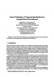
I. I NTRODUCTION Typically today’s hardware designs are Systems on Chip (SoC) including Networks on Chip (NoC). This is achieved by assembling many functional cores subject to intellectual property (IP cores) and connecting them via bus structures. Often multiple different protocols are used in the interconnect of a single system. Correct behavior of the communication interfaces is crucial for the operation of the full system and a bottleneck in today’s design flows. This particularly holds for SoCs having more than one bus. Here, we propose a methodology to automatically generate a provably complete verification suite for the formal verification of bus bridges. Bus bridges are dedicated hardware cores that connect two buses, e.g. if they run different protocols or to decouple different parts of the system. The coarse structure of most bus bridges is very similar. Both protocols are implemented in terms of a master and a slave component in the bus bridge itself. Fig. 1 shows an abstract view of a bus bridge. Requests originating on Bus A are handled by the slave interface Slave A. These requests are passed to Protocol B which often involves internal storage and a transformation step. Finally, the master interface Master B passes the request to Bus B. Analogously, response data from Bus B is mapped back to Bus A. The complexity of designing and verifying a bus bridge depends on how similar or different the Protocols A and B are and on the protocols themselves. There are several types of transformations that may be necessary in order to correctly pass a request from one bus to the other. Address translations are needed whenever the buses have different address spaces. If Protocols A and B do not belong to the same protocol family, also commands have to be transformed. Such translations range from simply substituting the operation codes to more complex operations like splitting up bursts or joining single transactions to bursts. Even within a single protocol family, individual configurations often differ in the subset of implemented commands and in the bit widths of address and data signals resulting in different protocols. Blocking and non-blocking transactions have to be respected. Finally, even given a precise specification of the connected protocols, there remains a degree of freedom in how to implement a bus bridge. Depending on the requirements with respect to chip area This work was supported in part by the German Federal Ministry of Education and Research (BMBF) within the project VerisoftXT under contract no. 01 IS 07008 C.
Fig. 1.
Overview of a bus bridge
and performance, the designer chooses (among other parameters) the size and depth of data buffers, whether to implement only a subset of operations, and whether to use pipelining of different phases of transactions. As all these decisions influence the architecture of the bus bridge, an automatic verification approach needs to take into account system-level knowledge, like throughput, real-time constraints etc. This flexibility and configurability of design specifications has to be met when developing an automatic verification approach. A related area is transducer synthesis, i.e. the automatic synthesis translating one protocol into another protocol. There exist both library-based [15], [4], [5] and protocol specification based [11], [3], [13] approaches to automatically generate hardware cores that translate between different protocols. However, verification of such synthesis steps is required and is even harder as different implementations are valid for the same specification. An automated verification approach based on the analysis of simulation traces is described in [12]. Another approach for the automatic verification of bus interfaces has been proposed in [8]. A generator produces a property suite for the verification of OCP interfaces. Neither the automatic verification of a full bus bridge is addressed nor can the functional completeness of the verification suite be guaranteed. In this work, we propose a methodology to assist the automatic generation of a functionally complete verification suite for bus bridges. The underlying generic model allows us to formally verify a wide range of implementations including features like transaction pipelining. Our main contribution is the underlying generic model used for verification. Once the model is available and configured to match the actual bus bridge, the generation of the formal properties is straightforward and tool-driven. The generated set of formal properties is functionally complete by construction due to the use of the Gap Free Verification (GFV) methodology [1], [2] and confirmed by the OneSpin 360 MV tool [10]1 . We exemplify our approach for bus bridges having interfaces to the Open Core Protocol (OCP) [9]. The highly configurable OCP standard specifies a variety of different actual protocols which are of practical interest. For other protocol specifications than OCP the 1 The GFV methodology itself is not focus of this work. We refer the interested reader to [1], [2]
write
Master-FSM
read
READY
Signal Mapping, FIFO Operations
Spec
idle
II. P RELIMINARIES To keep the paper self-contained, all necessary definitions are given in this section. After a brief introduction into verification, an overview of OCP is given. A. Verification Methodology The basic idea of the underlying formal verification approach is checking the design against a set of properties describing the correct behavior of the design. In the used methodology, the behavior is split up and described by operation properties. Each of the properties describes an operation of the Design Under Verification (DUV), possibly spanning multiple clock cycles. Thereby, all the outputs during the operation and some conceptual state of the DUV at the end of the operation need to be described unambiguously. Each operation is a transition of one conceptual state of the design to another conceptual state. As a result the set of properties forms a Conceptual State Machine (CSM) that describes the design at the specification level. Paths in the CSM correspond to allowed sequences of design operations. The properties are chained together by defining for each property the exact time point where the control is handed over to the successor property, also called right hook of the property. Example 1: Assume that the operations of a design are read and write. The write-transaction can be processed immediately, while the read-transaction needs to wait for the data to be available (i.e. it is split into three operations). Fig. 2 shows the CSM of this design that has two conceptual states, READY and READ-BUSY. The properties are shown at the edges in the CSM. Since the write-operation is completed within a single cycle, the operation does not change the conceptual state. The read-operation is verified using three properties. First, the design requests to read data and changes the conceptual state to READ-BUSY. The state is active until data is available (property wait), before the transition read is enabled and the state machine returns to the READY state. The property idle verifies the behavior when no read or write is requested. By this, the design is verified. Additionally to the CSM the verification tool can be supported by using invariants. Proven invariants can safely be reused as constraints in other parts of the DUV. This enables compositional verification and is e.g. used in [6]. As a design typically only works correctly within the specified environment, this environment has to be modeled during verification as well. This includes the modeling of protocols used by connected components. Here, Finite State Machines (FSMs) are used for this purpose. These FSMs are described in terms of constraints. The FSMs ensure the valid behavior of protocol states, i.e. it is not the aim to verify the robustness of the design against violations of the protocol specification by the environment.
Design
A simple conceptual state machine
proposed verification approach can be applied as well when the design matches the generic verification model. Our approach only requires a minimal amount of manual setup work. The run times to automatically generate the verification suite are negligible. The paper is structured as follows. Basic definitions are given in the following section. In Section III the general idea is sketched, while Section IV describes the approach in more detail. After an evaluation of the approach in Section V, the paper is concluded in Section VI.
Slave-CSM
FIFO-CSM
Master-CSM
Slave
FIFO
Master
Spec
Slave-FSM
Auto. gen.
read init
Fig. 2.
Inputs
READ-BUSY
wait
Bus A
Fig. 3.
Bus B
Overview of generated properties and user-required input
The functional completeness of the verification suite is guaranteed by construction using the Gap-Free Verification (GFV) methodology [1], [2]. The verification tool OneSpin 360 MV implements GFV and checks the completeness automatically. The methodology ensures that all operations in all modes are described and that all outputs are determined for any input trace. By this, successful GFV guarantees that no design behavior is missed during verification. This methodology is assumed as given in this work and the completeness of the generated verification suite is claimed in respect to the methodology. B. Open Core Protocol The openly licensed Open Core Protocol (OCP) [9] standard is a configurable specification of interfaces. Each actual configuration is a description of a particular protocol. For this purpose OCP specifies a wide range of transactions from simple write and read accesses to complex transactions in burst mode. The interface signals in OCP protocols are grouped into data-flow, sideband, and test signals. The two latter ones are optional groups of signals. Further, the dataflow signals are separated into the categories basic signals, simple extensions, burst extensions, tag extensions, and thread extensions. In this work we are supporting all basic signals for the automatic generation of properties for verifying the designs. However, due to a generic approach it is easy to integrate other signals as well. A configuration file for OCP describes which protocol elements are to be implemented, e.g. the transactions used, the handshake mechanisms for data transfer, how signals from the specification are named in the concrete implementation etc. Thus, OCP is a formal description of interfaces implying an underlying semantic. But other aspects like, e.g. response times after receiving a request are not specified in this file. III. G ENERAL I DEA In this section the general idea of the automatic approach for verifying bus bridges is sketched. Essentially, a generic model of bus bridges is the core of the approach. This generic model is configured to automatically generate the verification suite consisting of (1) CSMs formally capturing the behavior of the DUV and ensuring the completeness of verification, and (2) FSMs modeling the environment. The latter is required since the bus bridges often implicitly assume that the environment operates according to the specification, i.e. the DUV is not robust against protocol violation. The general flow for the presented approach can be seen in Fig. 3. The inputs for the approach are given in the upper part. The middle part sketches the components of the automatically generated verification suite. Finally, the design under verification is given in the lower part. Details on these three layers are described from bottom to top in the following. The bottom part sketches the design of the bus bridge to be considered. Compared to the general structure of a bus bridge
Bus A
Bus B
described in Section I, only one direction is considered as the other case is symmetric. For now, we assume that storage and mapping of transactions and addresses is done using a FIFO-like memory. The design is separated into three main parts Slave, FIFO, and Master. We call each of these three parts a cluster in the following. The separation of the functional blocks enables a compositional verification, ensuring scalability and efficiency of the proofs. In the middle layer of the figure the generated data and the model used by the verification approach is indicated. For each cluster of the DUV a CSM is generated. Invariants and constraints at the interfaces of the three clusters are generated automatically. Constraints for modeling the environment of the bus bridge are generated in terms of FSMs. The upper part shows all information required as input data for the automatic generation. More precisely, the buses connected to the bridge are generically described by protocol specifications for the corresponding slave and master, respectively. The communication between slave and master in the bridge is modeled using generic FIFO memories. The automatically generated properties for the FIFOs are built on top of generic functions and predicates, e.g. push, pop, and empty, that have to be specified by the user to adapt the properties to a specific design. For this purpose the user manually specifies these predicates that are specific to a particular implementation. Given a designer’s knowledge this is typically easily done. Furthermore, the depth of the FIFO, i.e. the number of entries which can be saved, has to be specified manually (in the special case of depth 0 no data is stored but passed through combinatorially). Note that the FIFO depth depends on the DUV implementation and not on the connected interfaces. We assume that two FIFO-like communication channels are used to separate (1) the transactions from slave to the master and (2) the responses from the master to the slave. Further, it is assumed that the functionality of these channels can be expressed using generic FIFO instructions. The FIFOs between the slave and the master form the interface from Protocol A to Protocol B. Thus, according to our approach, the abstract view of a bus bridge consists of two transformations. The transactions of Protocol A are transformed to a generic sequential FIFO protocol by the slave, which is then transformed to Protocol B on the master side. One example are different bus widths that require splitting of transactions from the wider bus into multiple transactions on the smaller bus. Note that while the current implementation of our approach covers the basic cases for the OCP protocol, the nature of the FIFO protocol is specific to the implementation of the DUV. Therefore, the mapping of the generic FIFO interface to the actual implementation will need the designer’s knowledge for more complex designs. In summary, the following input needs is required to automatically generate the property set: • A protocol specification of the buses, e.g. a textual OCP configuration file • A signal mapping of specification signal names to actual names in the design • Functions describing the internal implementation of the communication channels between master and slave as a generic FIFO and the translation of transactions (in terms of concrete verification source code) • Design specific parameters which cannot be extracted from the specification of the connected components, e.g. pipeline depth and response times Example 2: Throughout this paper, the design of the bus bridge in Fig. 4(a) is used as a running example. The connecting buses run OCP/IP protocols in two different configurations. The master of Bus A (left side) is connected to a slave and the slave of Bus B (right side) is connected to a master, respectively. External components connected to the bus bridge are not shown in the figure. Also, the actual implementation of other components connected to the bus is not
Clk SReset push
pop
MCmd’
MAddr
rw
rw’
MAddr’
MData
addr
addr’
MData’
MCmd
SCmdAccept
Slave
FIFO
wdata
wdata’
full
empty
SResp SData
MDataValid
Master
SCmdAccept’
rvalid
SResp’
rdata
SData’ SDataAccept
(a) Design t=0
t=1
t=2
t=3
t=4
Clk MCmd
WR
IDLE
SCmdAccept push rw pop rw0 MCmd0
IDLE
WR
MDataValid SDataAccept
(b) Example trace for a write transaction Fig. 4.
Running Example
required. Only the specification in terms of generated FSMs is used for the automatic verification approach. Other bus participants are assumed to comply with the specified protocol. Internally, the slave communicates with the master using a FIFO that is synchronized via a clock signal. All components are reset via the SReset signal. A command is specified via the MCmd signal and can either be IDLE (no request), WR (write request), or RD (read request). Depending on the chosen command, the signals MAddr and MData specify an address (to write to or to read from) and data in case of a write access. As return value, the slave accepts a command with SCmdAccept and responds to a request with SResp which returns DVA (data valid) in case of a valid response. Finally, in case of a read transaction the corresponding data is transmitted to the connected master via the SData signal. The master implements a data handshake mechanism using the MDataValid and SDataAccept signals, respectively2 . An example trace for a write transaction is given as a waveform in Fig. 4(b). After the command has been accepted, i.e. SCmdAccept asserts, the corresponding transaction and related data are stored in the internal FIFO signals. Afterwards, they are processed by the master interface to pass the transaction to Bus B. In case of a read transaction the read data would be returned to Bus A directly using the rvalid and rdata signals. IV. M ETHODOLOGY In this section the generation of the verification suite is described in more detail. First we show the structure of the verification model, i.e. the FSMs and CSMs, in Section IV-A and Section IV-B, respectively. Afterwards, we discuss the advantages of this approach in Section IV-C. A. Environment Constraints – Finite State Machines The FSMs model all valid protocol compliant behavior of the environment by implementing certain constraints on the primary inputs of the DUV. A transaction is split into multiple phases, like a request phase followed by a response phase. This is similar to 2 Although a data handshake is modeled, the transaction is still sequential, since the respective signals are sensitive to a common clock signal.
start∧!end / ev start∧end / ev
start∧!end / ev , nP := 1
P
P
start∧end / ev
P
end / ev
Request Phase (P =RQ) (ev =ACPT) start: MCmd 6= IDLE end: SCmdAccept = 1 Datahandshake Phase (P =DH) (ev =DATAVALID) start: ACPT ∧ dhreq end: SDataAccept = 1 Response Phase (P =RS) start: respreq ∧ [(ACPT∧!dhreq) ∨ DATAVALID] end: SResp = DVA
!start∧end∧nP ev , nP := 0 Fig. 6.
start∧!end / ev , nP := np + 1 start∧end / P ev !start∧end∧np > 1 / =1/ ev , nP := nP − 1
Extended state machine for pipelined transactions
single clock cycle, the counter remains unchanged. Technically, three further transitions have to be added to state P of the state machine. These transitions handle the cases, that a new phase is started, that a phase ended but the pipeline is still not empty, or that a phase completes in one clock cycle (see Fig. 6).
Fig. 5. Finite state machines for request, data handshake, and response phase
the configurable synthesis approach in [14]. Different scenarios are possible, e.g. in some cases a write request does not require a response phase. For each phase an FSM is created. Finishing one phase by reaching a certain state in the FSM triggers a state transition in the following FSM, i.e. the next phase. The parallel composition of the FSMs describes all traces conforming to any specified interaction on the bus. The separation into different phases allows for concurrent phases of different transactions. This kind of pipelining is common in modern protocols. Furthermore, this enables a simple description of transactions and the concept is easily extensible. Each state machine is built in the same manner. The general structure is given in the left hand side of Fig. 5. A state machine always consists of a phase variable P resulting in two states P and P indicating whether the phase is currently ongoing or not. The initial state is P . Transitions between states are labeled with a trigger and an event variable. A trigger is a Boolean expression composed of the expressions start and end. The trigger is always built in the same manner, but the start and end expressions are adjusted for each phase. The start expression indicates the beginning of a phase, whereby the end expression indicates the end of a phase and triggers the next phase, i.e. a transition in the corresponding FSM. If the FSM is in the initial state when start is asserted while end is not, then the state changes to P , meaning that the phase is ongoing. When end asserts as well, the phase finishes in the same clock cycle, thus, the transition results in the initial state. Being in the state P , when end asserts, then the state returns to the initial state P . In case no transition can be enabled, it is implicitly assumed that the state does not change and no event is emitted. In addition, whenever the constraint end asserts, a newly introduced event ev is emitted. This event is required for the parallel composition of the state machines and can be used as variable in the start expression of another state machine, i.e. another phase. Example 3: Concrete definitions of three state machines for three phases, namely the request, data handshake, and response phase are given in the table in the right hand side of Fig. 5. Considering the request phase, the phase state is indicated by RQ. The start condition is enabled whenever the command requested by the master MCmd is not IDLE. Further, the request phase ends whenever the command got accepted by the slave, i.e., the signal SCmdAccept asserts. The event, which is emitted by the request phase is ev =ACPT. A description of the other phases is given in a later example in Section IV-C. All the considered state machines are generated automatically from the protocol specification. With a slight extension of the FSMs, pipelining can be modeled. For this purpose, a counter nP is added to the state machine counting the number of the current transactions in the respective phase. The counter is increased whenever a transaction starts, i.e. the start constraint holds and it is decreased whenever a transaction ends, i.e. the end constraint holds. In case the phase completes within a
B. Conceptual State Machines Both the generated properties as well as the conceptual states describe the CSMs, i.e. the operation of the design to be verified. Each property is a transition in the CSM and corresponds to an operation the design can perform. For each cluster in the structural view of the design, i.e. slave, FIFOs, and master, a CSM is constructed (compare to Fig. 3). Analogously to the design of the FSMs described in the previous section, the properties of the CSMs are designed in a generic way to encapsulate the implementation details resulting from different designs. Therefore, the properties are expressed on top of an abstraction layer that hides the implementation details. This abstraction layer is given by a collection of predicates and functions, some of which are generated automatically. The remaining functions need to be supplied by the user to adapt the CSM to the DUV. In our approach, that is the description of the FIFO implementation. The properties have an implication structure – if the assume part evaluates to true, then the prove part needs to hold as well. Under the assumption that the design is in a certain conceptual state, the property proves that a transaction is correctly processed and that the design reaches the next conceptual state. During the operation all outputs to the adjacent clusters are specified, as well as the internal state of the cluster. The following example demonstrates this approach. Example 4: As an example the CSM for the master is given in Fig. 7. In this example, only non-blocking operations are allowed. Therefore the single conceptual state master ready is sufficient. All the properties immediately return to the single conceptual state master ready. Note, that properties typically cover several clock cycles even though they are given by a single transition in the CSM. Consider the property proving a correct read transaction as given in Fig. 8. Here, the property is written in ITL, a property language used in the OneSpin 360 MV verification tool. Alternatively, the whole approach could be implemented using System Verilog Assertions (SVA) [7]. Two time-points are declared, where tacc represents the acceptance of the command by the slave (line 3), and trsp represents the end of the response phase (line 4). In the freeze block, signals are captured at a certain time point. In this example, the current command (line 6) and address (line 7) in the FIFO are read at time t, the clock cycle where the operation is assumed to start. According to the CSM, the source state, i.e. master ready is assumed by the
reset
Fig. 7.
master ready
read, write, idle
Overview of the generated conceptual state machines
property prop master read; for timepoints: t acc = t + 0..4 waits for b SCmdAccept; t rsp = t acc + 0..4 waits for b SResp != NULL; freeze: CMD = fifo Cmd(fifo back)@t; ADR = fifo Addr(fifo back)@t; assume: at t: master ready state; at t: CMD == RD; prove: during[t, t acc]: master cmd out(CMD, ADR); during[t, t acc−1]: fifo pop idle; at t acc: fifo pop; at t rsp: resq valid; at t acc+1: master ready state; end property;
C
Slave
A
Fig. 9.
A C C A
FIFOs
A C C A
Master
C A
Constraints (C) and invariants (A) in compositional verification
The approach guarantees that the generated properties completely cover the behavior of the bus bridge. As explained earlier this is guaranteed by using the GFV methodology and formally proven by OneSpin 360 MV. C. Discussion
Fig. 8.
ITL description of the master’s read property
property (line 9). Besides that, a read command is pending in the FIFO (line 10). In the prove part of the property, the correct execution of the read operation has to be proven (lines 12–15) and that the property ends in the conceptual state master ready (line 16) which is the property’s target state in the CSM. For the read operation, the predicate master cmd out checks that the read command from the FIFO will be correctly issued on the bus (line 12). While before the acceptance of the command (tacc ), no pop action is allowed on the FIFO (fifo pop idle, line 13), at the time-point of acceptance the current transaction is popped from the FIFO (line 14). Finally, as soon as a response is coming in from the bus, the response queue (resq) will be validated by the master (line 15). The response queue is the communication channel between master and slave and in this specific design realized by a combinatorial signal. Note that the property allows the overlapping of successive transactions, i.e. pipelining can easily be modeled: As soon as the conceptual state master ready (the target state in the CSM) is reached at time point tacc + 1, the control is handed over to the next property, which could be read, write, or idle. The response phase however ends later at time point trsp , which means that the next transaction is allowed to start before the current transaction is finished. In a similar manner, properties are generated with the respective proof goals for all the edges in the CSMs of the master and the slave. In general, the properties for the slave are structured as follows. The conceptual state slave ready and an incoming command from Bus A are assumed. Furthermore, the FIFO needs to have at least one free entry. Then, the command is acknowledged on Bus A, a new transaction is issued on the FIFO interface as soon as the necessary data is available, and the system returns to the state slave ready. Similarly, a property for the master assumes a valid transaction in the FIFO. The property proves that the respective command is issued correctly on Bus B and that the transaction is removed from the FIFO. If a response is expected, response data is transferred to the slave by insertion into the response queue, and the system returns to the state master ready. In addition to these transaction properties, and to ensure a complete verification, there is an idle property for both master and slave, checking the behavior in cases where no transaction occurs. In order to ease the compositional verification, invariants are generated, including common proof goals of a cluster with respect to the interface of its adjacent clusters. For example, an invariant guarantees that there is no push operation taking place at the FIFO interface as long as the incoming bus is idle. Proven invariants can be used to constrain the inputs of adjacent clusters. This is depicted in Fig. 9. At the boundaries of the bus bridge, it is proven that the protocol specifications are respected by the DUV. Note that the invariants and constraints are generated such that no cyclic reasoning occurs [1], [2]. This is also checked automatically by the verification tool used.
Our approach has an underlying abstract model of bus bridges to be verified. Any implementation fitting into this model can be handled by the approach. To verify a design, a concise protocol specification is required and generic properties formally describing this specification must be generated automatically. However, the model is very generic and flexible. At the bus interfaces, a high level of automation is achieved. Using the encapsulation by constraints and decoupled state machines, it is easy to allow different configurations of designs without changing the basic structure. For every basic OCP configuration the resulting FSMs representing the transactions will look as in Fig. 5, i.e. even when no data handshake phase is required by the specification, the FSM is generated. Using sub-expressions in the constraints start and end ensures flexibility. Further, due to the use of event triggers, flexibility is ensured. Other bus bridges running protocols that are similar to OCP can be verified using the same methodology. Example 5: Whether the data handshake phase and response phase are specified in the OCP configuration, can be obtained from the variables dhreq and respreq, respectively. Assuming that a data handshake phase is not specified, i.e. dhreq is always false, the respective start constraint never holds. However, in case a response is required (respreq is true) and a request phase ends, i.e. the ACPT signal asserts, the start constraint of the response phase evaluates to true. Thus, the FSM for the response phase is triggered by the ACPT signal, when there is no data handshake phase specified, otherwise, the FSM is triggered by the DATAVALID event, emitted by the data handshake FSM. Verifying the internal communication and the translation of the transactions is more difficult. The abstract FIFO interface allows for a high degree of automation, as most of the proof goals for the data flow are generated. FIFOs are typical elements used in bus bridges for the internal communication. Thus, for designs of lower complexity, the mapping from the abstract interface to the actual implementation is easy. At the same time, the generic interface offers enough flexibility to be applicable to more complex designs which might not use FIFOs as communication channels. As an example, we considered a bus bridge with incompatible data widths (32 bits and 16 bits, respectively). In this case, the transformation, i.e. the splitting of transactions is easily encapsulated in the push action of the FIFOs. Using the conceptual state machine of a design as a starting point for the generation of the properties allows high flexibility and extensibility of the approach. By adjusting the structure of the CSM, a variety of different designs can be modeled. For example, when switching from non-blocking reads to blocking read transactions, a CSM as shown in Fig. 2 is used. Based on this CSM, also burst transactions can be modeled by adding further transitions (i.e. properties) describing the processing of the successive data items during a burst. Essentially, the core structure of the CSM remains the same. Further transactions in the specification extend these by additional transitions and potentially by new intermediate states.
Table I E VALUATION R ESULTS Lines of Code Slave FSM 219 Master FSM 324 Properties 244 Invariants 76 Conceptual States 33 Completeness Check 120 Predicates 64 FIFO Predicates 108 Sum 1,188 (a) Generated property set
Invariants Properties Completeness check for slave Completeness check for FIFO Completeness check for master Sum
Proof time (s) 2.36 4.76 2.44 1.02 25.15 35.73
Memory (MB) 1,503 1,650 1,055 564 6,088
(b) Proof-time and memory usage for property verification
V. E VALUATION This section presents a case study demonstrating our approach. The design of the running example (Fig. 4) is used with the following configuration. The slave uses a basic protocol with a request and response phase, providing a read-operation and a write-operation. On the second bus, the master uses a more enhanced protocol with an additional data handshake phase. The communication from slave to master is realized by a FIFO, whereas the opposite direction is realized by a combinatorial signal. The design has a size of about 600 lines of Verilog code. Based on an OCP configuration file consisting of 64 lines of code, the generated verification suite consists of 11 properties, 10 constraints, 13 assertions, and 90 predicates. Additionally, 21 predicates were specified manually to describe the FIFO. Note, that most of the manually specified predicates consist of a few lines only (compare with Table I(a)). Example 6: To demonstrate the compactness of the manually generated FIFO predicates, consider Fig. 10 showing three predicates. Here, the functions for the two pointers to the front and the back of the FIFO as well as the data pointer to the top entry are described. As can be seen, in this particular design they encapsulate concrete design signals. However, when e.g. using fifo front in other invariants and properties, the actual signal fifo/write ptr is referenced implicitly. The verification suite has a size of about 1,200 lines of code. A more detailed overview of the lines of code can be obtained from Table I(a). As can be seen, the majority of the code is created for the environment constraints and for the actual properties. In total only 108 lines are not generated automatically but result from the included FIFO predicates that are manually specified, i.e. 91% of the verification code is automatically generated. The design was verified on a 3 GHz AMD Athlon Dual Core processor using 4 GB of main memory running Linux 2.6.31. The automatic generation of the verification suite took less than one second after providing the user input. Run time and memory requirements for the verification are listed in Table I(b). The data is separated for invariants, properties, and all completeness checks for the three clusters. All checks can be performed in several seconds, in total 35.73 seconds. However, the completeness check of the master used 70% of the overall run time. This is explained by the additional data handshake phase implemented in the master component of the bridge. The approach offers further advantages. Generated close to the specification level, the properties are readable and have the same underlying structure. Thus, properties are easily understood by the designer for debugging purposes. Moreover, our methodology provides a structured way to the verification of the bus bridges.
1 2 3
macro unsigned fifo front := fifo/write ptr; end macro; macro unsigned fifo back := fifo/read ptr; end macro; macro unsigned fifo top := fifo entry(fifo back); end macro; Fig. 10.
Example predicates for three selected FIFO functions
VI. C ONCLUSION In this work, a verification methodology for bus bridges is presented. A partially automatic approach has been proposed that generates a provably functionally complete verification suite based on GFV. No design behavior can be missed. The design is separated into three clusters and the properties are generated based on abstract descriptions of both the design and the environment. As input the protocol specification and some implementation specific parameters are required. Thus, the approach can be applied to different designs. We evaluated the approach using OCP/IP as protocol specification, which describes a large family of protocols. In this case 91% of the verification suite were automatically generated. In future work we will improve the degree of automation by using formal methods to derive certain implementation specific parameters that are currently user input. Furthermore, we will apply the methodology to ease the debugging step for failing properties as well. Currently counterexamples have to be analyzed at a low level. Mapping these counterexamples to a higher level of abstraction assists the designer in this step. R EFERENCES [1] J. Bormann. Vollst¨andige formale Verifikation. PhD thesis, Technische Universit¨at Kaiserslautern, 2009. [2] J. Bormann and H. Busch. Method for the determination of the quality of a set of properties, usable for the verification and specification of circuits, 2009. US Patent 7571398, priority Sep 2005, granted Aug 4th, 2009. [3] V. D’Silva, S. Ramesh, and A. Sowmya. Bridge over troubled wrappers: Automated interface synthesis. In VLSI Design, pages 189–194. IEEE Computer Society, 2004. [4] F. Gharsalli, S. Meftali, F. Rousseau, and A. A. Jerraya. Automatic generation of embedded memory wrapper for multiprocessor SoC. In Design Automation Conference (DAC), pages 596–601. ACM, 2002. [5] A. Grasset, F. Rousseau, and A. A. Jerraya. Automatic generation of component wrappers by composition of hardware library elements starting from communication service specification. In IEEE International Workshop on Rapid System Prototyping (RSP), pages 47–53. IEEE Computer Society, 2005. [6] T. A. Henzinger, M. Minea, and V. S. Prabhu. Assume-guarantee reasoning for hierarchical hybrid systems. In Hybrid Systems: Computation and Control, 4th International Workshop, HSCC 2001, Rome, Italy, March 28-30, 2001, Proceedings, pages 275–290, 2001. [7] IEEE System Verilog Working Group. IEEE Standard for SystemVerilog – Unified Hardware Design, Specification, and Verification (IEEE Std 1800-2005). IEEE, 2005. [8] J. Moondanos, L. Loh, and H. Stump. OCP and verification of configurable OCP interfaces. Technical report, Jasper Design Automation, 2010. presentation slides, http://www.ocpip.org/uploads/dynamic areas/Ct9Rr6XmkN84Y6MvTou u/947/OCP.IP.2010.ppt, last access 2010-05-11. [9] OCP-IP. Open Core Protocol International Partnership, 2010. http://www.ocpip.org. [10] OneSpin Solutions GmbH. GapFreeVerification Process Manual. Technical report, Munich, 2009. Version 2009 12. [11] R. Passerone, J. A. Rowson, and A. L. Sangiovanni-Vincentelli. Automatic synthesis of interfaces between incompatible protocols. In Design Automation Conference (DAC), pages 8–13, 1998. [12] F. Rogin, T. Klotz, G. Fey, R. Drechsler, and S. R¨ulke. Automatic Generation of Complex Properties for Hardware Designs. In Design, Automation, and Test in Europe (DATE), pages 545–548, 2008. [13] A. Roychoudhury, P. S. Thiagarajan, T.-A. Tran, and V. A. Zvereva. Automatic generation of protocol converters from scenario-based specifications. In IEEE Real-Time Systems Symposium (RTSS), pages 447–458. IEEE Computer Society, 2004. [14] S. Watanabe, K. Seto, Y. Ishikawa, S. Komatsu, and M. Fujita. Protocol transducer synthesis using divide and conquer approach. In Asia and South Pacific Design Automation Conference (ASP-DAC), pages 280– 285. IEEE, 2007. [15] D. Wingard. MicroNetwork-Based Integration for SoCs. In Design Automation Conference (DAC), pages 673–677. ACM, 2001.