Proceedings of the 17th World Congress The International Federation of Automatic Control Seoul, Korea, July 6-11, 2008
Property Patterns for the Formal Verification of Automated Production Systems ? Jos´ e Creissac Campos ∗ Jos´ e Machado ∗∗ Eurico Seabra ∗∗ ∗
Departamento de Inform´ atica/CCTC, Universidade do Minho, Braga, Portugal, (e-mail:
[email protected]). ∗∗ Departamento de Engenharia Mecˆ anica, Universidade do Minho, Guimar˜ aes, Portugal, (e-mail: {jmachado,eseabra}@dem.uminho.pt) Abstract: In recent years, several approaches to the analysis of automation systems dependability through the application of formal verification techniques have been proposed. Much of the research has been concerned with the modelling languages used, and how best to express the automation systems, so that automated verification might be possible. Less attention, however, has been devoted to the process of writing properties that accurately capture the requirements that need verification. This is however a crucial aspect of the verification process. Writing appropriate properties, in a logic suitable for verification, is a skilful process, and indeed there have been reports of properties being wrongly expressed. In this paper we put forward a tool and a collection of property patterns that aim at providing help in this area. Keywords: Analysis of reliability and safety, Methodologies and tools for analysis of complexity, Modelling 1. INTRODUCTION The reliability, availability, and maintainability of automated systems (i.e. its safe operation) have a direct impact on people and goods safety. Guaranteeing the safe operation of a system requires an holistic approach to design, that takes safety considerations into account from the early design stages through to operational exploitation. Formal verification of software is becoming established as a useful and powerful technique for guaranteeing the correctness of software artefacts in general. This is also the case for industrial controllers analysis [Moon, 1994]. Formal Verification’s main advantage is that it enables analysis of all possible system behaviour. Typical mentioned disadvantages relate to the time and computational resources needed for the attainment of formal verification results, and to the level of expertise needed to apply the verification techniques. In this paper we address this latter issue. In recent years, several approaches to applying formal verification techniques on automation systems dependability have been proposed. These range from formal verification by theorem proving [Roussel and Denis, 2002] to formal verification by model-checking [Smet and Rossi, 2002, Rossi, 2003, Gaid et al., 2005, Machado et al., 2006]. As verification tools gain popularity, the problem arises of making its use scale to more realistic settings. The ? This work was carried out in the context of the SCAPS Project supported by FCT, the Portuguese Foundation for Science and Technology, and FEDER, the European regional development fund, under contract POCI/EME/61425/2004, and which deals with safety control of automated production systems.
978-1-1234-7890-2/08/$20.00 © 2008 IFAC
scalability of such tools is affected by a number of factors, from the scalability of the algorithms being used as the size and complexity of the problems being faced increases, to their proneness to human errors during the modelling and interpretation of results phases as potential users become less proficient in the verification techniques being applied ”under the hood”. We refer to this latter aspect as the accessibility of the verification tools. We have been working on this issue of making verification more accessible. In order to help the analysis of PLCs (Programmable Logic Controllers) programs, it is important to facilitate the use of automated reasoning tools. This can be done at several levels. Three are: • help in deducing the controller model; • help in writing properties for analysis; • help in analysing the results. One specific aspect that deserves attention is the writing of properties to be verified. Meaningful properties can be hard to write and hard to get right. This is even more the case when we consider the behaviour of complex automated systems, whose requirements are difficult to describe. Writing a property for verification is a two step process: (1) we must first identify what the relevant properties of a given system are, (2) and then we must decide how to correctly express them in the logic of the verification tool. Step 1 is domain dependent, and largely relies on knowledge about the specific system being designed/verified and what its properties should be. Step 2 is a technical step. A
5107
10.3182/20080706-5-KR-1001.4192
17th IFAC World Congress (IFAC'08) Seoul, Korea, July 6-11, 2008
correct understanding of the model, the requirement, and the logic in which properties are expressed is needed in order to guarantee that the property being tested correctly encodes the intent of the testing process. This is not a trivial step. In [Dwyer et al., 1998] an example is reported where a property was wrongly expressed. The process is made more complex when the models are developed in such a way that verification must only be performed at certain specific points in the evolution of the system (for example, because not all states in the model represent stable system states). In this paper we look at how the process of expressing properties can be supported. Our approach is to provide designers with patterns that can be instantiated to produce properties of interest. A tool is being developed to support the approach. The paper is structured as follows: • Section 2 describes our approach to modelling, and the impact it has on how properties must be expressed; • Section 3 discusses property patterns, and in particular those proposed by [Dwyer et al., 1998]; • Section 4 presents the tool we are developing to support the use of patterns; • Section 5 presents a study of automation related properties; • Section 6 introduces a new pattern collection for automated production systems’ verification that resulted from the study; • finally, in Section 7 we discuss the results that have been achieved and put forward lines for further work. 2. MODELLING APPROACH Model-checking techniques [B´erard et al., 1999] have been employed for the formal verification of DES (Discrete Event Systems) automation for the past twelve years. A finite state system can be represented by a labelled state transition graph, where labels of a state are the values of atomic propositions in that state (for example the values of the latches). Properties about the system are expressed as formulae in temporal logic of which the state transition system is to be a ”model”. Model-checking consists of traversing the graph of the transition system and of verifying that it satisfies the formula representing the property, i.e., the system is a model of the property. As part of a dependable controller design approach, the target verification system model may comprise [Frey and Litz, 2000] either the controller on its own, assumed to be placed in an open-loop on the plant (non model-based verification) or the controller + plant set interacting within a closed-loop (model-based verification). Both in the non model-based and model-based formal verification there are some properties that can be systematically verified. For instance, some properties of the controller model like safety and liveness properties, related with the internal states of the controller program [Bornot et al., 2000], can be deduced in a systematized way. Also, some properties, related with the plant model, like safety, liveness, and other properties related with the ”stability” of the plant model, can be expressed always in a sys-
tematized way. This concept of ”stability” is related with states of the plant model that may not correspond to true states of the plant behaviour. The concept of ”stability” associated at the plant model is well explained by Machado et al. [2006]. By studying and identifying the properties used for the verification of DES automation, it becomes possible to systematize the writing of such properties in an automatic way. That is the goal of this work. 3. PROPERTY SPECIFICATION PATTERNS A number of classifications for property specifications in the context of model checking approaches have been proposed. Manna and Pnueli [1991] used a syntactic approach, proposing a taxonomy of LTL (Linear Time Logic) formulae. The taxonomy is based on the operators used in each formula, therefore it covers all possible specifications that can be expressed in the logic. The categories they define, however, tend to be rather broad, and came from a theoretical perspective. While they can be useful to classify existing specifications, they provide little support for the process of generating new specifications. In [Manna and Pnueli, 1990] the same authors had proposed a more pragmatic approach, a proof system that handles three basic types of properties: invariance (expressing that something holds in all states of the system – for example, the liquid in a tank will always remain below a predefined maximum value); response (expressing cause-effect relations – for example, if the tank becomes full the output valve will be open); and precedence (expressing something must happen before something else – for example, before the valve is closed, the tank must be empty). Dwyer et al. [1998] propose a more elaborate system of patterns. They carried out an extensive review of published property specifications, and identified recurring patterns which they organised into an hierarchy. The term “design pattern” was first introduced by Gamma et al. [1995] as a means of capturing and transmitting experts’ knowledge in the field of object-oriented design. A pattern is not simply a mechanism to classify some artefact (be it a object-oriented design, or a property specification) into a category. A pattern’s goal is to capture proven solutions to known problems, and demonstrate how they can be used in practice to solve the same or similar problems in new situations. With the above in mind, Dwyer et al. [1998] provide, for each pattern, a description that includes the pattern’s intent, examples and known uses, relationships to other patterns, and mappings to different logics (in particular, LTL and CTL – Computational Tree Logic [Clarke et al., 1986]). Additionally, the patterns can be tailored with scopes: they can be applied to the whole of the model’s behaviour, or be restricted to work between specified conditions. A full account of all the patterns is out the scope of this paper. Briefly, three classes of patterns are identified: occurrence (dealing with whether specific conditions are verified in the behaviour of the system), order (dealing
5108
17th IFAC World Congress (IFAC'08) Seoul, Korea, July 6-11, 2008
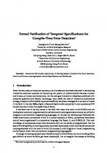
Instantiation of patterns to produce a property specification can be done in two modes: manual mode and automatic mode. In manual mode, the values for the patterns parameters are indicated manually by the users. In figure 1 the user has provided the value “ev1” to parameter P, and the value “ac=1” to parameter Q. Since the pattern being used is Response, the property being constructed states that “ac=1” is a response to “ev1” (in CTL: ”AG(ev1 → AF(ac=1))”). In automatic mode, the system reads the attributes from a model and the user can use pull down menus to select which attributes are used in the parameters. For each pattern, codifications in CTL and LTL are available. This way, the formulae are created in a transparent manner. As illustrated in figure 1 the tool supports both the patterns in [Dwyer et al., 1998] (Dwyer), and the patterns we will be introducing in section 6 (SCAPS). To this end, a DTD for the description of patterns has been developed, and support for reading pattern collections expressed in XML, in accordance to that DTD, integrated into the tool. 5. A STUDY OF AUTOMATION RELATED PROPERTIES Fig. 1. The patterns tool with the order in which events/conditions occur), and compound (dealing with chains of events/conditions). Some of the most relevant patterns are:
Patterns do not provide concrete solutions. Instead, they provide templates that must be tailored for specific purposes. Hence, when attempting to apply the patterns to a specific area two questions arise:
• absence – a given state/event (P ) does not occur (in CTL this is expressed as “AG(¬P )”) • universality – a given state/event (P ) occurs always (in CTL this is expressed as “AG(P )”) • response – a given state/event (P ) must always be followed by a state/event (Q) (in CTL this is expressed as “AG(P →AF(Q))”) • precedence – a given state/event (P ) always precedes some state/event (Q) (in CTL this is expressed as “A[¬Q W P ]”)
• On the one hand, the patterns should capture the relevant knowledge for the specific area being considered. Is all the relevant knowledge (or, at least, enough of the relevant knowledge) captured by the current set of patterns being used? • On the other hand, the manner in which the properties are formulated should be adequate to the logics and modelling approaches used in the area of interest. Are the languages and encoding strategies used in the patterns adequate? In order to answer these two questions we carried out a study of property specifications in the area of automation control (our area of interest in the current context).
4. TOOL SUPPORT In our own work on formal verification we have been developing tools to tailor the verification process to specific domains. We are particularly interested in making the verification process as accessible as possible. This includes shielding the person performing the verification from the technicalities of the process as much as possible. Of course this must be done without hindering the verification process itself. While the patterns can be a useful tool, the manual process of selecting and applying a pattern is error prone, and such error can be hard to detect.
The objective of the study was similar to that carried out by Dwyer et al. [1998]: to collect properties used in the literature, and look for possible patterns. The justification to perform a new instance of a study of this type was two fold: on the one hand the original study already had a number of years, begging the question of whether new patterns had arisen; on the other hand, we were interested in a particular application of the verification technology, and in determining whether domain specific patterns are being used in that context.
In order to address this, we decided to develop a tool to help the generation of properties from the combination of models and patterns. The tool (Properties Editor – see figure 1) is based on the notion of property patterns described above. A list of property patterns and help for instantiating those patterns with the attributes and actions in the model are provided.
A number of papers and theses was analysed. Space constraints prevent an exhaustive enumeration. Relevant examples are [Bornot et al., 2000, Yang et al., 2001b, Mertke and Frey, 2001, Rossi, 2003, Zoubek, 2004]. In many cases the papers concentrated mainly in the modelling approaches, with little being said about the verification itself. Consequently, in those cases little information was provided about which properties were verified, and how they came about. This reinforced our perception that work is needed in this area.
The patterns include all the information in the original patterns, such as intention and known uses.
5109
17th IFAC World Congress (IFAC'08) Seoul, Korea, July 6-11, 2008
A total of 6 main case studies (plus a number of smaller examples) was analysed, resulting in over 70 property specifications. These properties were then aggregated into six classes according to their syntactical structure, and the type of application. The six identified classes are (typical formulations are introduced, they all are expressed LTL except the first and last that are in CTL): (1) Possibility – “AG EF P”, meaning P is always possible; (2) Fairness – “G F P”, meaning P occurs infinitely often; (3) Absence – “G (stable→ ¬P)” , meaning P does not occur (in stable states); (4) Response – “G (P → F(stable → Q))”, meaning after P, Q will happen (in a stable state); (5) Universality – “G P”, meaning P occurs in every state; (6) Precedence – “A[¬Q W P]”, meaning P always precedes Q (this pattern was very rare). Comparing these classes back with the patterns defined by Dwyer et al. [1998] we find that four of the classes corresponded to patterns in the patterns systems (3 to 6), while two of them do not (1 and 2). However, even for the patterns that have correspondence, the formulation of the properties do not totally coincide. Given the particular modelling approach used in the field, a considerable number of properties used special variables to restrict the analysis to stable states. While this can at first seem a detail to be dealt with during pattern instantiation, it has in fact a great impact on the structure of the properties. The introduction of such variables requires considerable knowledge of the logics being used if it is to be done properly. The conclusion, then, is that we should define a new pattern system best adapted to the area of automation. These patterns should include the Possibility and Fairness patterns, and provision for the consideration of stable states (in a similar way as scope is already being considered).
Basic formulation CTL: AG EF P P is always possible. Stable formulation CTL: AG EF (stable∧P ) P is always possible in a stable state. Examples Rossi [2003] uses this pattern to express the absence of dead code. The author writes a family of properties AG EF (etat = pre i ) where etat is a variable that captures the current state of the system and pre i are the possible execution steps. Hence, what each properties says is that a particular execution step is always possible. Bornot et al. [2000] use this pattern to express that two events (s4 and sfc top s3 .s8 ) have to synchronise repeatedly. AG EF (s4 ∧ sfc top s3 .s8 ) In fact, this is a mislead application of the pattern since proving the property does not guarantee that the events ever synchronise in any specific execution of the model (see intent above and the next pattern). 6.2 Fairness Pattern This is another pattern not present in the original pattern collection by Dwyer et al. [1998]. Despite not being one of the most used, it was used to express relevant properties. Intent To express that some event or state is repeatedly possible throughout the execution of the system. Unlike the possibility pattern, this pattern does require that the state or event actually happens in the execution of the model. Basic formulation
6. A NEW PATTERN COLLECTION
LTL: G F P In this section we describe the proposed patterns. For each pattern we list its intent, its formulation in LTL and CTL (when available), and some examples of use, as well as its adaptation to consider stable states only. Where available, examples of inappropriate use are also provided. Throughout the descriptions P and Q will be used to denote variables that need instantiation. 6.1 Possibility Pattern This pattern was not present in the original pattern collection used for the properties editor tool. Interestingly, it was found to be one of the three most common patterns in the literature. Whether this is a specificity of this area is a question that needs further analysis. Intent To express that some event or state is always possible throughout the execution of the system. Note that it does not require that the state or event actually happens in a specific execution of the model, only that it is possible that it will.
P happens repeatedly. Stable formulation LTL: G F (stable∧P ) P happens repeatedly in stable states. Examples Rossi [2003] uses this pattern to express dead lock freedom G F fdc where fdc represents the end of the processing cycle. The objective is to expresses that the processing cycle repeatedly ends. Note however, that a behaviour which satisfies the above property is that where the system does not leave the fdc condition. Hence, the verification should be complemented with the analysis of the fairness of other steps. 6.3 Absence Pattern This was one of the most common patterns.
5110
17th IFAC World Congress (IFAC'08) Seoul, Korea, July 6-11, 2008
Intent To express that some event or state is not present throughout the execution of the system. Basic formulation
Note that, depending on the specific analysis being performed, we might wish to state that P must also be considered in a stable state only (P∧stable). Examples Yang et al. [2001b] use this pattern to express that a pump should not carry on working when the level of a tank is running low AG(Lev < 2 → AF (¬m2 ∧ ¬vB ∧ ¬v4 )) where Lev again represents the Level of the tank, m2 is the state of the pump, and vB and v4 are valves’ states. In this case it is not being required that the level is measured at a stable state.
CTL: AG (¬P ) LTL: G (¬P ) P is never possible. Stable formulation CTL: AG ¬(stable∧P ) LTL: G ¬(stable∧P ) P is never possible in a stable state. Examples Yang et al. [2001b] use this pattern repeatedly to express both that a tank should not become empty and that it should not overflow AG¬(Lev = 0 ) ∧ AG¬(Lev = 6 ) where Lev represents the Level of the tank. Mertke and Frey [2001] use this pattern to express the following functional requirement “While the pressure is above 6.1 bar, motor 1 should not be turned on and motor 2 should not be turned on.”
Bornot et al. [2000] use this pattern to express that a specific condition on the state of the system (active ∧ s6) immediately leads to a transition, and not to another (x ∧ y → s7 ∧ ¬s8). AG((active ∧ s6 ) → AX (x ∧ y → s7 ∧ ¬s8 )) Rossi [2003] uses this pattern to express the system responds to signals G(E STOP → F (fdc → (¬MR ∧ ¬MP0 ∧ MP1 ))) where fdc is our stable variable, E STOP is the signal, and ¬MR ∧ ¬MP0 ∧ MP1 characterises the correct response of the system. Note that, assuming stable will eventually hold, F (stable → b) is equivalent to F (stable ∧ b). 6.5 Universality Pattern
resulting in AG¬(rdy plc ∧ (¬i1 ) ∧ (o1 ∨ o2 )) where rdy plc plays the role of our stable variable, i1 represents the pressure condition, and o1 and o2 are the states of the engines. 6.4 Response Pattern This is another of the most commonly used patterns. A point that must be decided upon is whether the response must be immediate. Patterns will be provided for both the case when the response does not need to be immediate, and for the immediate case. Intent To express that some event or state will always lead (immediately, or at some point in the future) to another event or state.
This is one of the patterns that was present in the original patterns’ collection and could be observed in our review of the literature. Intent To express that some event or state occurs in every state of the execution of the system. This pattern is in effect the opposite of the absence pattern. Basic formulation CTL: AG P LTL: G P P is always true. Stable formulation CTL: AG (stable→ P ) LTL: G (stable→ P ) P is true in all stable states.
Basic formulation
Examples Bornot et al. [2000] use this pattern to express that two events always synchronise. AG(s4 ↔ sfc top s3 .s8 ) where s4 and sfc top s3.s8 are the two event that should always be synchronised.
CTL (immediately): AG (P → AX Q) LTL (immediately): G (P → X Q) CTL (eventually): AG (P → AF Q) LTL (eventually): G (P → F Q) P always leads to Q.
Yang et al. [2001a] use this pattern to express that the temperature of a reactor always stays inside a desirable range CTL (immediately): AG (P → A[¬stable U (stable∧Q)]) AG(reactor .TREA > 0 ∧ reactor .TREA < 6 ) LTL (immediately): G (P → (¬stable U (stable∧Q))) CTL (eventually): AG (P → AF (stable∧Q)) 6.6 Precedence Pattern LTL (eventually): G (P → F (stable∧Q)) Stable formulation
P always lead to Q at some future stable state (or at the next stable state, in the immediate case).
Few instances of this pattern were found. However, because it was a pattern present in the original pattern
5111
17th IFAC World Congress (IFAC'08) Seoul, Korea, July 6-11, 2008
system, the decision was taken of including it in this collection. Intent To express that some event or state must occur before some other event or state. Conceptually this pattern is the opposite of the response pattern. The pattern uses the weak until operator. Because this operator is not usually supported by verification tools, we provide alternative formulations with the more standard operators. Basic formulation CTL: A[¬ Q W P] CTL (alternative): ¬E[¬P U (Q∧¬P)] LTL: G ¬Q W P LTL (alternative): F(Q) → (¬Q U (P ∧¬Q)) P always precedes Q. Stable formulation CTL: A[¬ (stable∧Q) W (stable∧P)] CTL (alternative): ¬E[¬(stable∧P) U (stable∧Q∧¬P)] LTL: G ¬(stable∧Q) W (stable∧P) LTL (alternative): F(stable∧Q) → (¬(stable∧Q) U (stable∧P ∧¬Q)) P always precedes Q in stable states. Examples Rossi [2003] uses this pattern to express that a drill motor should always be stopped (¬dp drill motor) before a conveyor belt is started (dp conveyor motor) G(¬dp conveyor motor W (¬dp drill motor )) 7. CONCLUSIONS AND FUTURE WORK In recent years, several approaches to applying formal verification techniques on automation systems dependability have been proposed. As verification tools gain popularity, the problem arises of making them more accessible. In this paper we have looked at the issue of supporting the expression of property specifications. We have briefly introduced a tool that supports the use of specification patterns for the generation of properties for verification. A study was carried out of properties present in the automated production systems analysis literature. A collection of patterns has been put forward as a result of this study, and was described in the paper. Future work includes continuing to collect data from the verification literature, in order to further validate and perfect the current set of patterns. Further improvements on the tool include the possibility of applying patterns to families of states/events. This would allow, for example, to check the fairness of all events in a system by applying the pattern to all events, instead of having to individually apply the pattern to each event. There is the need also to apply the tool to a number of case studies in order to better assess its value in the verification process. REFERENCES B. B´erard, M. Bidoit, A. Finkel, F. Laroussinie, A. Petit, L. Petrucci, and P. Schnoebelen. Systems and Soft-
ware Verification: Model-Checking techniques and tools. Springer, 1999. S. Bornot, R. Huuck, B. Lukoschus, and Y. Lakhnech. Verification of sequential function charts using SMV. In International Conference on Parallel and Distributed Processing Techniques and Applications (PDPTA 2000), volume V, pages 2987–2993. CSREA Press, June 2000. E.M. Clarke, E.A. Emerson, and A.P. Sistla. Automatic verification of finite-state concurrent systems using temporal logic specifications. ACM Transactions on Programming Languages and Systems, 8(2):244–263, 1986. M.B. Dwyer, G.S. Avrunin, and J.C. Corbett. Patterns in property specification for finite-state verification. In B. Boehm, D. Garlan, and J. Kramer, editors, 21st Intern. Conf. on Software Engineering (ICSE’98), pages 411–420. IEEE Computer Society Press, 1998. G. Frey and L. Litz. Formal method in plc programming. In Proc. IEEE Int. Conf. on Systems Man and Cybernetics, pages 2431–2436, 2000. M. Gaid, B. B´erard, and O. Smet. Verification of an evaporator system with uppaal. European Journal of Automated Systems, 39(9):1079–1098, 2005. E. Gamma, R. Helm, R. Johnson, and J. Vlissides. Design Patterns. Addison-Wesley Professional Computing Series. Addison-Wesley, 1995. J. Machado, B. Denis, and J.-J. Lesage. A generic approach to build plant models for DES verification purposes. In 8th International Workshop On Discrete Event Systems (WODES’06), pages 407–412, July 2006. Z. Manna and A. Pnueli. Tools and rules for the practicing verifier. Technical Report STAN-CS-90-1321, Stanford University, July 1990. Z. Manna and A. Pnueli. Temporal Verification of Reactive Systems: Specification. Springer-Verlag, 1991. T. Mertke and G. Frey. Formal verification of PLCprograms generated from signal interpreted petri nets. In Proceedings of the 2001 IEEE Systems, Man, and Cybernetics Conference, pages 2700–2705. IEEE, 2001. I. Moon. Modeling programmable logic controllers for logic verification. IEEE Control Systems, 14(2):53–59, 1994. O. Rossi. Validation formelle de programmes ladder pour ´ automates programmables industriels. PhD thesis, Ecole Normale Sup´erieure de Cachan, France, June 2003. J-M. Roussel and B. Denis. Safety properties verification of ladder diagram programs. Journal Europ´een des Syst´emes Automatis´es, 36:905–917, 2002. O. De Smet and O. Rossi. Verification of a controller for a flexible manufacturing line written in ladder diagram via model-checking. In 21th American Control Conference, ACC’02, pages 4147–4152, Anchorage, USA, May 2002. CDROM paper n.734. S.H. Yang, O. Stursberg, P.W.H. Chung, and S. Kowalewski. Automatic safety analysis of computer-controlled plants. Computers and Chemical Engineering, 25:913–922, 2001a. S.H. Yang, L.S. Tan, and C.H. He. Automatic verification of safety interlock systems for industrial processes. Journal of Loss Prevention in the Process Industries, 14: 379–386, 2001b. Bohum´ır Zoubek. Automatic verification of temporal and timed properties of control programs. PhD thesis, School of Computing, The University of Birmingham, September 2004.
5112