Jerzy MIKULIK, Katarzyna MAJEWSKA AGH University of Science and Technology, Department of Engineering Management
Automatic recognition of threats in mantraps using MATLAB software Streszczenie: Artykuł przedstawia propozycję systemu kontroli dostępu bazującego na wykorzystaniu śluzy oraz analizie obrazów z kamer przemysłowych. Omówiona została struktura systemu oraz kolejne operacje na rejestrowanych obrazach wykonywane przez program, a także ich podstawy teoretyczne. Szczególna uwaga poświęcona została wykorzystywanym sposobom rejestracji, zapisu i kompresji obrazu oraz przekształceniom kontekstowym i bezkontekstowym obrazu, mającym decydujący wpływ na końcowy efekt w postaci materiału wykorzystywanego do porównania z wcześniej utworzoną bazą wzorców. (Automatyczne rozpoznawanie zagrożeń w śluzach osobowych z wykorzystaniem oprogramowania MATLAB) Abstract: This paper presents a proposal of an access control system based on the use of a mantrap and an analysis of images from closed-circuit television cameras. The structure of the system is discussed as well as subsequent operations on the recorded images performed by the program, and their theoretical basis. Particular attention has been paid to the applied methods of registration, recording and image compression, as well as to contextual and non-contextual processing of images, which has a decisive impact on the final effect in the form of material used for comparison with a previously created database of reference images.
Słowa kluczowe: kontrola dostępu, śluza osobowa, analiza obrazu. Keywords: access control, mantrap, image analysis.
General concept of the method A mantrap is an object, which structural properties and, above all, the idea of operation, allow for automatic detection of threats in access control systems. The main feature of a mantrap is that only one person may be present inside during a single control cycle. This allows the implementation of different methods of recognizing such situations and thus, reducing the level of risk caused by attempts of unauthorized access and acts of sabotage. The described method of identifying the number of persons present inside a mantrap on the basis of images taken with digital cameras is based on continuous monitoring of the space inside a mantrap. The images are analyzed and processed in order to ensure the propriety of authorized entrance of a user to a protected zone, taking into account the criterion of the presence of only one person inside the mantrap during a single control cycle. Several fundamental conditions can be identified in the operating concept of a mantrap, i.e.: continuous recording of images from digital cameras placed inside a mantrap, extracting contours of objects present inside a mantrap at a given time on registered individual images, processing and analysis of images aiming at detecting and comparing objects or people, comparing images with reference images stored in a database, decisions to grant or deny access and activation of automatic access control devices, creating a passing-through report for a given user. An important feature of this concept is the assumption that we do not detect a person's identity, we only want to eliminate the possibility of more than one user entering a mantrap, and therefore, most of interfering factors, such as clothing or biological characteristics of persons are not taken into account. This reduces significantly the complexity of calculations and operations performed. Brightness of the lighting has a major impact on the correctness of recognition (the light should be indirect, it should come from the direction of cameras and its intensity at a height of 80 cm from the floor should range between 200-300 lux).This is because during the construction of a mantrap using a
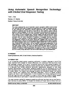
similar technique of detecting the number of people, minimization of reflections from walls and floors is required, as well as ensuring the stability of lighting while opening or closing the door and the stability of cameras. Moreover, an important feature of the applied method is that it allows for detection of objects left inside a mantrap, which can simply be a result of human absent-mindedness, but also of sabotage. Figure 1 presents two situations of passing through a mantrap, which illustrate the principle of its operation and one of the main assumptions – accepting the presence of only one individual inside. The lower part of Figure 1 depicts subsequent stages of authorized passing-through of one user, culminating in the granting of access to a protected zone, while the upper part - a situation of an authorized entry into a mantrap, however as a result of detecting an incorrect number of people present inside, ending up in the denial of access to the protected area. The method of identifying the number of people inside a mantrap is aimed at preventing phenomena such as passback (an attempt to pass through an access control system together with another person, without being, unlike that person, noticed by the system), tailgating (an attempt to remain in close proximity to another person and behaviour resulting in access control system recognizing two people as one), escorting or forced entry. The occurrence of these phenomena causes a serious threat to a protected zone because of the lack of information on the identity of persons staying in this area, and sometimes even on their presence. The Manlock application developed specifically for this purpose is proposed to be used to identify the number of people inside a mantrap. It is intended to present a method of identifying the number of people inside a mantrap based on an analysis of static images from digital cameras, as well as to enable drawing conclusions about the effectiveness of this method and its practical application in access control systems with high security class [1, 2, 3]. The application was implemented in the Matlab environment. Apart from standard features of the package, when writing the program many specialized functions available through the Image Processing Toolbox and used for image analysis and processing were utilized [4].
222 PRZEGLĄD ELEKTROTECHNICZNY (Electrical Review), ISSN 0033-2097, R. 88 NR 9a/2012
Fig. 1. Identification of the number of people inside a mantrap based on an image from digital cameras - the concept of operation (top view)
Preparatory activities Digital image recording For the purposes of the described method of identification we can distinguish two main systems of digital image recording found in closed-circuit video camera systems, which could be used in the proposed system: registration of images using cameras with CCD (Charge Coupled Device) sensors, which are systems of many light-sensitive elements, each of which records and then allows the reading of an electrical signal proportional to the amount of light falling on it, registration of images using cameras equipped with CMOS (Complementary Metal Oxide Semiconductor) sensors, which are advanced systems, consisting of millions of light-sensitive elements, working on a photodiode. From the point of view of applying in digital cameras transducers suitable for image registration in the interior of a mantrap, it is much more advantageous to use CCD sensors because of their better adaptability to poor lighting conditions. At the same time adequate quality of recorded images is maintained because in this case technical parameters of the image itself are important and not its artistic value. For the purposes of computer processing, an image is subject to discretization and quantization. Discretization consists in two-dimensional image sampling in specific points in space (usually in rectangular grid nodes); while quantization consists in assigning to each point a discrete value representing a range from a continuous span of brightness values. The process of discretization and quantization can be written in the form of transforms (1), (2): (1)
[m, n] T1{x, y}
(2)
[l ] T2 {l a }
where: T1 - discretization operator, T2 - quantization operator, {x, y} - a set of continuous values of coordinates of a source image, [m, n] - a set of discrete coordinates of digital image points, la - continuous brightness values of a source point, l - discrete brightness values of a point of a digital image. Properties of optoelectronic circuits determine the output image resolution. Spatial resolution resulting from discretization can be defined as follows (3):
(3)
dx dy , M N
where: dx and dy represent the linear size of a source image horizontally and vertically, while M and N represent the maximum number of points of a digital image horizontally and vertically. In image processing and analysis this resolution is defined as the product of MxN. Colour resolution, in the simplest case, is defined by the number of bits that we use to record levels of brightness R = 2b. As a result of discretization and quantization we obtain an image on the monitor, which can be written as a twodimensional MxN matrix with non-negative elements taking a finite number of values (4): (4)
l L(m, n)
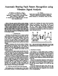
where: L - function of discrete coordinates of a digital image [m, n], l - discrete brightness values of a pixel of a digital image. Recording and compression In image processing the following types of images are used most frequently: black and white (binary), monochromatic, colour. In black and white images two levels of gray are distinguished, and just one bit is enough to record them. In monochromatic images we can identify many gray levels, 256 in most applications, and to record them one byte is sufficient. Colour images can be recorded in the RGB standard, in which all colours are created from three primary colours (red-green-blue) in an additive way. In this case, image recording is carried out through three colour intensity matrices, whose elements take values from a range, e.g. [0,255], with 256 levels of colour saturation. In the discussed problem, monochrome images saved in TIFF format (Tagged-lmage File Format) size 220 x 220 pixels have been used as input images for further digital processing by the application after the registration. Figure 2 presents examples of such images. TIFF is a standard format of image storing as a bitmap file, which may in a lossless way store information about
PRZEGLĄD ELEKTROTECHNICZNY (Electrical Review), ISSN 0033-2097, R. 88 NR 9a/2012
223
luminance components of an image obtained by digital recording. In the TIFF format various levels of brightness of each pixel of a digital image are successively stored. This format enables saving images in a compressed form. The basic compression algorithm is LZW (Lempel-Ziv-Welch), which
ensures lossless compression. LZW is a dictionary-based compression algorithm, extremely fast and efficient especially for monochrome images, and it is widely used in TIFF compression.
Fig. 2. Images from CCTV cameras, saved in TIFF format to be used for further digital processing
Thus, a preliminary analysis of images from cameras placed inside a mantrap is based on graphic files stored in TIFF format as a monochrome image with 256 shades of gray scale. The implementation of basic transformations enables the performance of further operations on binary images. The application which analyzes the images gives the possibility of their non-contextual processing, saved in shades of gray scale in order to improve their quality and to control basic operating parameters that affect the results of further structural analysis. Loading a file in TIFF format and saving it in the Matlab workspace in the form of a matrix is performed using the imread command. Integers and double precision numbers are the available data types that represent the images. An example of a matrix representing a section of the image in Figure 2 (red frame) in 256 shades of gray scale for the integer-type data, after the operation of three-fold reduction using the nearest neighbour method (the imresize function), in Matlab looks as follows:
(5)
166 166 161 123 L1 130 161 167 172 171
166 166 166 166 166 166 166 166 166 166 166 166 166 166 161 162 162 162 161 163 166 123 122 124 121 120 128 167 116 123 108 119 103 133 167 161 160 157 140 109 133 166 166 164 158 146 109 135 167 171 171 159 151 111 136 166 172 173 161 155 114 137 166
and for double-precision data types: 0.65098 0.65098 0.63137 0.48235 (6) L2 0.5098 0.63137 0.6549 0.67451 0.67059
0.65098 0.65098 0.63137 0.48235
0.65098 0.65098 0.65098 0.65098 0.63529 0.63529 0.47843 0.48627
0.65098 0.65098 0.63529 0.47451
0.65098 0.65098 0.63137 0.47059
0.4549 0.63137 0.65098 0.67059
0.48235 0.62745 0.64314 0.67059
0.42353 0.61569 0.61961 0.62353
0.46667 0.54902 0.57255 0.59216
0.40392 0.42745 0.42745 0.43529
0.67451
0.67843 0.63137
0.60784
0.44706
0.65098 0.65098 0.65098 0.65098 0.63922 0.65098 0.50196 0.6549 0.52157 0.6549 0.52157 0.65098 0.52941 0.6549 0.53333 0.65098 0.53725 0.65098
Non-contextual processing Non-contextual image transformations (point transformations) mean the transformations that concern the grey or saturation level of each point separately [5]. In point transformations, values of grey level (or saturation) of individual points of an image are the result of algebraic operations performed only on a given point, whereas in this case any surrounding points are completely disregarded. Non-contextual image transformations can be classified as follows [4]: arithmetic image transformations, geometric image transformations, point transformations of parts of an image, image binarization , determination of object parameters on an image. Non-contextual arithmetic operations performed in the Manlock programme on images recorded both from the front and the side of a mantrap consist primarily in subtraction of two images. In most cases, these two images consist of an image of the background registered with an empty mantrap, and an image recorded when there is a user or an analyzed object inside the mantrap. As a result of the subtraction of images we obtain an image devoid of any background from the range not occupied by the shape of the object. It constitutes the initial material for further processing, which consists in determining edges of the object found in the image. In general, algebraic operations on two images can be written as operations on individual components of matrixes: (7)
L 2(m, n) L1a(m, n), L1b(m, n)
where: m and n are coordinates of corresponding points of an images, Ф is a binary scalar function, L2 (m, n) means a point in the resulting image, while L1a (m, n) and L1b (m, n) denote points in the source images. In the case of monochrome image subtraction we obtain: (8)
L 2(m, n) L1a (m, n) L1b(m, n)
224 PRZEGLĄD ELEKTROTECHNICZNY (Electrical Review), ISSN 0033-2097, R. 88 NR 9a/2012
which in Matlab means subtraction of grey levels of corresponding points of the images. a)
b)
a mantrap. During the analysis of edge detection methods it is necessary to define precisely the notion of the edge. It is a line dividing areas of different brightness and different saturation levels. An edge is thus a transition area between two parts of an image having different brightness. The process of edge detection is performed using the ready digital filters implemented in the Image Processing Toolbox, used for edge detection, performed as the edge function offered by Matlab, in which one of the arguments allows for the selection of an appropriate filtration method. The edge function is able to realize the Laplacian, Sobel, Prewitt, and Roberts filters, returning an image of edges in those places where the gradient takes its maximum value. These are high-pass filters, dedicated to extract from an image components responsible for rapid changes of brightness, and therefore, also edges, contours and fine texture elements. The Roberts filter is clearly oriented in nature. It is focused on reinforcing elements running at an angle of 45°, which is demonstrated by the form of its convolution matrix, applied in the analysis for each pixel of the image being processed (9): (9)
0 0 0 K R 1 0 0 0 1 0
The family of Prewitt filters is also oriented in nature. In the case of these filters, as opposed to Roberts filters, horizontal elements are accented, with the convolution matrix having the following form (10): (10)
Fig. 3. Subtraction of images a) input images, b) images obtained after subtraction using imabsdiff and imsubtract functions, source: own material
It should be noted that this operation is possible only when matrices representing the images have the same dimensions. To achieve this, for images of different sizes we must match their resolution. In Matlab this is done by using the imresize function with interpolation or nearest neighbour, or bilinear or quadratic method. In Matlab subtraction can be implemented directly by the subtraction operation on matrices representing the images or using the imabsdiff (as a result we obtain the absolute value of the difference) or imsubtract (subtraction of images, or of a constant from the image) functions. An example of subtraction of two images is shown in Figure 3. Image filtration Image filtration is a contextual transformation and it is used to extract some information from an image in order to perform further processing. Another use for filtration is removing noise from an image or image blur. The tasks of filtering include such activities as: improving technical quality of an image for example in case of a blur, or moving, reinforcement or suppression of certain parts of an image according to a model, edge detection, corner detection. Edge Detection The first context operation performed by the Manlock application on previously prepared images is determining edges of an object, both on the front and the side views of
K Ph
1 1 1 0 0 0 1 1 1
By a simple transposition of matrices (10) it is possible to obtain a mask used for the detection of vertical edges (11):
(11)
K Pv
1 0 1 1 0 1 1 0 1
On the other hand, the Sobel filter is a more advanced highpass filter enabled by the edge function. It is because with filtration by means of its mask it is possible to enhance the impact of the immediate environment of the processed pixel. Respectively, the horizontal and the vertical Sobel mask have the following form (12):
(12)
1 2 1 1 0 1 K Sv 0 0 0 , K Sh 2 0 2 1 2 1 1 0 1
It is noteworthy that the Sobel masks can be freely rotated, not only by 90o, but also by any angle. This allows for the determination of gradients in different directions. However, the most advanced high-pass filter offered by the edge function is the Laplace method. Its indisputable advantage is the fact that it allows setting free from the oriented operation of gradient filters. In this way, in the process of edge detection not only the edges of a certain nature are emphasized, but all edges and contours of an image, regardless of the angle at which they are running.
PRZEGLĄD ELEKTROTECHNICZNY (Electrical Review), ISSN 0033-2097, R. 88 NR 9a/2012
225
The convolution matrix for the Laplacian filter is often symmetrical, and an example of it could be as follows (13):
(13)
0 1 0 K L 1 4 1 0 1 0
However, for the use in the Manlock application even a more advanced method offered by the edge function has been chosen, the Canny filter aimed at detecting local gradient maxima. It uses two reference thresholds that allow the connection of weak edges to the main edges, if they are adjoining. It is more susceptible to noise from the others, however it is more accurate and presently it is probably the most widely used method of detecting edges of an image. The subsequent steps in the Canny edge detection method are as follows. First it is necessary to perform blurring of the input image, which is done by means of the Gaussian filter with symmetrical convolution matrix having a size adapted to the previously calculated standard deviation of noise from the input image derived from subtraction. An example of a matrix convolution may look as follows (14):
(14)
2 4 5 4 2 4 9 12 9 4 K G 5 12 15 12 5 4 9 12 9 4 2 4 5 4 2
Edges on an image can run at different angles. Therefore, in order to have them correctly identified, one of the most popular high-pass detection filters is applied. In the Manlock application the Sobel filter is used, it works very fast and it is easy to make with it eight processes - two runs (connected with reversals) for each of the four directions (0o, 45o, 90o and 135o).. The results for two processes connected with reversals on a given direction are averaged geometrically. In this way tables are obtained, containing gradient values for each direction for each pixel S 1, S 2, ....Thus, for each pixel with (i, j) coordinates it is possible to determine a gradient angle on the basis of the gradient value of neighbours (15): (15)
number of edges less relevant to the overview image analysis.
S i, j i, j arctan 2 S1 i, j
Each use of the Sobel filter leaves edge approximations. They have a certain thickness, typically greater than 1 pixel, and have a blur as you move away from the theoretical edge. Therefore, some unnecessary pixels of the image are left, which can then be removed using an array of gradient values for each pixel of the image. On the basis of the array, a theoretical direction of the edge shape is determined, and the pixels located in a direction perpendicular to it and reducing their brightness can be totally extinguished. After this operation, the designated edges reduce their thickness and become more distinct, because as a result of the performed operations the contrast has increased. Figure 4 presents examples of the effects of the filters used for the detection of image edges. It can be seen that the Canny filter gives a clear picture, despite finding a larger
Fig. 4. Image of edges detected using the Canny method (left) and the Laplace method (right), source: own material
The main objective in further image processing is to create a filled contour of an object, therefore additional edges detected by the Canny filter do not interfere, and often they are even a little helpful for further processing. The filled image is subsequently added to a database as a reference image, and during the actual operation of the program the image transformed into such a form is compared with reference standards. The filling of an object is performed using morphological transformations dilatation and filling holes in the object. Morphological image transformations Morphological transformations are among the most important image transformations, allowing for more complex operations associated with the analysis of the shape of individual image elements and their position in relation to each other. These are some of the fundamental transformations used in image analysis, and the selective character of their contextual operations is one of their main characteristics. Morphological image transformations are associated with changes in gray level or saturation of a given point in a resulting image, depending both on the parameters of a given point in the input image as well as the parameters of neighbouring points. These relationships are described by a so-called structural template, which defines pixel values and their distribution. In Matlab the bwmorph function is available, which, depending on the applied operator, enables a number of morphological transformations, including the following: erosion and dilation (erode and dilate operators), openings and closings (open and close operators), thickening and thinning (thicken and thin operators) skeletonization (skel operator), filling of contours and isolated points (majority and fill operators). A computer image is created as a mosaic of points, usually located in grid nodes. In the current generation of imaging systems usually two grid types are used: hexagonal and square. Morphological transformations alter the grey level or hue of a given point of an image, depending on the value of gray level or hue of the points surrounding it. The number of points taken into consideration is determined by a so-called structuring element. A structuring element is a subset of elements of an artificially created segment of an image with one point highlighted, a so-called origin. A circle would be the most desirable structuring element. However, restrictions associated with the discrete structure of a computer image cause that the shape of a rectangle is the most often used structuring element [4]. Nevertheless, there is a possibility to choose different types of structuring elements and matching their sizes both with dilation and
226 PRZEGLĄD ELEKTROTECHNICZNY (Electrical Review), ISSN 0033-2097, R. 88 NR 9a/2012
image erosion performed subsequently, as this functionality is offered by the Manlock application. It is possible to select the following elements: disk (circle), diamond, line, square and rectangle, each of them gives different results during the image dilation and erosion operations.
sequentially, and it is the final operation performed in the Manlock programme on transformed images captured inside a mantrap. For the operations of opening and closing of a binary image, we can write (20), (21): (20)
O( L, SE ) D( E ( L, SE ); SE )
(21)
C ( L, SE ) E ( D( L, SE ); SE )
For monochrome images the formula for opening and closing take the following form (22), (23):
Fig. 5. Examples of structuring elements from the left disk of radius 4 and diamond of radius 3, source: own material
Erosion and dilation Erosion and dilation are among the basic morphological transformations. The simplest way to imagine the process of erosion on binary images is as cutting off a strip of a specified width along the edge of an object. In morphological transformations the width of the strip that is cut off is determined by the size of the structuring element. The structuring element is rolled on the inside edge of the object. Subsequent positions of the central point of the structuring element set a new boarder of the object after erosion. On the other hand, dilation is a process reverse to the process of erosion. On binary images it can be thought of as adding a strip of a desired width along the edge of an object. In morphological transformations the width of the added strip is determined by the size of the structuring element. The structuring element is rolled on the outside edge of the object. Subsequent positions of the central point of the structuring element set a new boarder of the object after dilatation. According to Minkowski algebra, the processes of erosion and dilation for binary images can be written as (16), (17): (16)
E ( L, SE ) L( SE )
( L se)
seSE
(17)
D( L, SE ) L SE
( L se)
(22)
OGRAY ( L, SE ) max min L(m, n) m , nSE m , nSE
(23)
C GRAY ( L, SE ) min max L(m, n) m , nSE m , nSE
where L (m, n) denotes brightness of the pixel having (m, n) coordinates, and SE – the structuring element. Filling contours Another morphological transformation is filling holes in an object. This operation can be useful in situations where for example you want to determine the external shape of an object without taking into account holes, and to eliminate reflexions caused by the lighting of a scene. In Manlock the imfill function is used to fill contours, and the next chapter presents the way it works.
Fig. 6. Images with a marked border of an object detected inside a mantrap using the operation of subtraction, source: own material
seSE
where L and SE denote respectively a transformed image and a structuring element, while and stand for operators of Minkowski subtraction and addition respectively. For monochrome images the formula for erosion and dilation take the following form (18), (19): (18)
E GRAY ( L, SE ) min L(m, n)
(19)
DGRAY ( L, SE ) max L(m, n)
m , nSE
m , nSE
where L (m, n) denotes brightness of the pixel having (m, n) coordinates, and SE – the structuring element.
Fig. 7. Images after dilatation, the structuring element is a disk of radius 2, the edges were earlier detected using the Canny method
Opening and closing The open and close operations are compounds of the previously discussed transformations, i.e. erosion and dilation. The opening operation consists in erosion and dilation performed sequentially. The closing operation consists in dilation and erosion operations performed
PRZEGLĄD ELEKTROTECHNICZNY (Electrical Review), ISSN 0033-2097, R. 88 NR 9a/2012
227
Fig. 8. Images after filling holes using the imfill function
Fig. 9. Images after the erosion operation, the structuring element is a disk of radius 1, source: own material
Process of image registration and analysis The following figures present the effect of various morphological operations, until the moment of obtaining the final transformed image [6]. The resulting image Figure 9 is saved in a database of reference images. When such a database already exists, each new image from the camera is transformed into this form, compared with reference images and properly classified. The Manlock program allows switching views of transformed images in order to observe the effect of operators. Classifier Although images from a camera are saved as a matrix of 220 x 220 pixels, it was much more convenient for further calculations to save them as a vector (48 400 items) that was subsequently standardized. The number of images classified using the Hamming neural network [7] proposed for the classification depends on the number of reference images registered, and it can be increased during the program operation by adding new reference images. All network parameters are then aligned automatically, without affecting the network performance. It was shown experimentally that for the stabilization of a network 500 learning cycles are sufficient to achieve satisfactory results. To each reference image saved in a database an index is assigned, classifying it to the images that can be granted or denied access to a safety zone. The final decision to grant access is taken only in cases when the images taken both from the front and the side of a mantrap are recognized as reference images having the tag enabling the access. In any other situation, access to an area protected by a mantrap is impossible. The Manlock program also has the option to create and display reports that contain basic information about the status of a mantrap, such as date and time of granting or denying access to a safety zone.
Fig. 10. Input image fed to the network (top) and the reference image recognized by the network (bottom)
Integration with cctv system According to the assumption of the presented method, an image is registered in a mantrap using a digital camera. Virtually all methods of image registration and processing applied nowadays are based on high-performance digital technology. Advanced compression algorithms and file formats allow for the registration of images with all details at moments interesting for us, and its detailed analysis using specialized software. Moreover, it can all happen in real time. Continuous observation of registered images is aimed at preventing unauthorized access or burglary, and in case of such an occurrence it is meant to serve as evidence. Due to the fact that inside a mantrap images are recorded on a continuous basis in order to identify the number of people present inside, there are no obstacles to register them on data carriers used for the purposes of STD CCTV. The MPEG-7 format of registered images seems to be an excellent and modern solution for this purpose. MPEG-7 is a standard that defines the description language of the content of multimedia objects (called Multimedia Content Description Interface).While previous standards of the MPEG group (MPEG-1, MPEG-2 and MPEG-4) addressed the standardization of a compact representation of the contents of multimedia objects and only MPEG-4 attempted to transcend slightly beyond this functionality, the MPEG-7 standard fully regulates descriptions of this content. These descriptions, the socalled descriptors, can be created by the operator (e.g. the opening credits of a digital film, or details of a manufacturing process), and some of them can be automatically extracted from the digital medium (e.g. identification of dominant colours or features of a face image). These descriptions in turn can be used to create indexes of materials to facilitate a search for objects in local archives and, more importantly, also in dispersed archives of a computer network, which can be a corporate security system, a system of state institutions with high control and security level, and many others [8, 9, 10].
228 PRZEGLĄD ELEKTROTECHNICZNY (Electrical Review), ISSN 0033-2097, R. 88 NR 9a/2012
One of the main tasks facing the MPEG-7 standard is effective description of multimedia materials. The main types of digital materials include texts, graphics, images, audio, video, animation and film. Archiving digital material always comprises archiving a description, as well as indexes of contents of an archive built on these descriptions. A multimedia archive consists of a content and metadata. Metadata consist of descriptions of digital materials and their indexes. Therefore, metadata allow for the identification of contents (by man) and quick search of materials (by a computer system). The primary objective of MPEG-7 standard is to create standardized tools for describing multimedia objects. These descriptions are created for effective selection of digital materials. Selection criteria may relate to various aspects of digital media. Generally, as in a classic film we deal with metadata relating to an object as a product (e.g. authors, producer) as well as semantic information on the content of the object, i.e. what it deals with. Metadata of a product and its contents are generated by humans in the form of appropriate XML documents. MPEG-7 has already standardized a significant part of information on signal characteristics of entire objects (e.g. dominant colour of an image, texture, shape of an object, intensity of motion in a picture, melody line of a soundtrack), or their part (region, segment). Consequently, it may be applied wherever multimedia information plays the fundamental role. Therefore, there are many different areas of activity, in which it can be used. From the perspective of this publication, these certainly include monitoring and video surveillance (such as traffic control, road transportation, non-invasive measurements in conditions of difficult access) or investigators (e.g. recognition of characteristic features of humans and institutions with high safety standards). Conclusions Tests of the proposed system allow drawing the conclusion that the method of identifying the number of persons based on the analysis of digital images from only two cameras using the Matlab environment produces good results, ensuring lower costs associated with building an infrastructure. Binarization of images allows for considerable reduction of the size of files containing
reference images stored in the program database. This has an important impact on the amount of space on data carriers needed for their storage, and this in turn influences the effectiveness of the Hamming network. The second key effect of reducing the file size is increasing the speed of its transmission. Files with reference images saved in TIFF format without any compression occupy less than 2KB. This allows the application of the proposed system also in wide area networks. REFERENCES [1] Mikulik J., Wybrane zagadnienia zapewnienia bezpieczeństwa i komfortu w budynkach, Uczelniane Wydawnictwa NaukowoDydaktyczne, 2008, Kraków [2] Polaczek T., Audyt bezpieczeństwa informacji w praktyce, Helion, 2007, Warszawa [3] Ross A., Security Engineering, Wiley Publishing, Inc., 2008, Indianapolis [4] Wróbel Z., Koprowski R., Praktyka przetwarzania obrazów w programie Matlab, Akademicka Oficyna Wydawnicza EXIT, 2004, Warszawa [5] Tadeusiewicz R., Korohoda P., Komputerowa analiza i przetwarzanie obrazów, Wydawnictwo Fundacji Postępu Telekomunikacji, 1997, Kraków [6] Szklarczyk M., Węglarz D., Analiza i implementacja programowa metod sterowania śluzami w systemach kontroli dostępu, na bazie programu Continuum, Politechnika Krakowska, 2005, Kraków [7] Tadeusiewicz R., Sieci neuronowe, Akademicka Oficyna Wydawnicza RM, 1993, Warszawa [8] Białas A., Bezpieczeństwo informacji i usług w nowoczesnej instytucji i firmie, Wydawnictwo Naukowo-Techniczne, 2006, Warsaw [9] Lehtinen R., Russell D. and Gangemi G.T., Computer Security Basics, 2nd ed., O'Reilly Media Inc., 2006, Sebastopol, CA. [10] Pipkin D. L., Information Security: Protecting the Global Enterprise, Prentice Hall PTR, 2000, New Jersey Autorzy: Dr hab. inż. Jerzy Mikulik – prof. AGH, AGH Akademia Górniczo-Hutnicza, Katedra Inżynierii Systemów, ul. Gramatyka 10, 30-067 Kraków, E-mail:
[email protected], Dr inż. Katarzyna Majewska, AGH Akademia Górniczo-Hutnicza, Katedra Inżynierii Systemów, ul. Gramatyka 10, 30-067 Kraków, E-mail:
[email protected]
PRZEGLĄD ELEKTROTECHNICZNY (Electrical Review), ISSN 0033-2097, R. 88 NR 9a/2012
229