(LFi), all of which collectively make the behavior of Mi particularly well-suited to handle domain Di. As a means to address uncertainty in execution environments,.
Proceedings of the ACM/IEEE 12th International Conference on Model Driven Engineering Languages and Systems (MoDELS), pp. 568–583, October 2008.
Automatically Generating Behavioral Models of Adaptive Systems to Address Uncertainty! Heather J. Goldsby and Betty H.C. Cheng {hjg,chengb}@cse.msu.edu Department of Computer Science and Engineering Michigan State University, 3115 Engineering Building East Lansing, Michigan 48824 USA
Abstract. Increasingly, high-assurance applications rely on dynamically adaptive systems (DASs) to respond to environmental changes, while satisfying functional requirements and non-functional preferences. Examples include critical infrastructure protection and transportation systems. A DAS comprises a collection of (non-adaptive) target systems (represented as UML models) and a set of adaptations that realize transitions among target systems. Two sources of uncertainty inherent to DASs are: (1) predicting the future execution environment, and (2) using functional and non-functional trade-offs to respond to the changing environment. To address this uncertainty, we are inspired by living organisms that are astonishingly adept at adapting to changing environmental conditions using evolution. In this paper, we describe a digital evolution-based approach to generating models that represent possible target systems suitable for different environmental conditions, enabling the developer to identify the functional and non-functional trade-offs between the models, and then assisting the developer in selecting target systems for the DAS.
1
Introduction
Increasingly, high-assurance applications rely on dynamically adaptive systems to react and respond to environmental changes, while continuing to meet functional requirements and make non-functional trade-offs. Examples include critical infrastructure protection and transportation systems. In an effort to promote separation of concerns, we consider a dynamically adaptive system (DAS) to comprise a collection of (non-adaptive) target systems and a set of adaptations that realize transitions among target systems in response to environmental changes. We use the term domain to refer to a specific set of environmental conditions to be handled by a given target system (e.g., noisy network, sensor failure, and low battery could all be true for one domain). Model-driven engineering, which !
This work has been supported in part by NSF grants EIA-0000433, CNS-0551622, CCF-0541131, IIP-0700329, CCF-0750787, Department of the Navy, Office of Naval Research under Grant No. N00014-01-1-0744, Siemens Corporate Research, and a Quality Fund Program grant from Michigan State University.
2
successively refines models from analysis to design and then automatically generates code [1], can be leveraged to support rigorous development of a DAS by modeling each of the target systems as a UML model (i.e., a class diagram and a behavioral model comprising a set of interacting state diagrams) and adaptations as transitions among them. There are two key sources of uncertainty inherent to applications warranting adaptation: (1) predicting the future execution environment, and (2) using the trade-offs in non-functional characteristics and functional behavior to respond to the changing environmental conditions. To address these uncertainty issues, we can learn from nature. Living organisms are astonishingly adept at adapting to changing environmental conditions using evolution. In this paper, we harness the power of evolution [2] to automatically generate a suite of behavioral models that represent possible target systems suitable for a variety of combinations of environmental conditions not explicitly specified by the developer. We then automatically identify the non-functional characteristics and latent functional properties (“corner properties” or implicit, not required behavior) of the models, thereby assisting the developer in identifying trade-offs between the models in order to select the models to use as target systems. Several architecture-based modeling approaches (e.g., [3–6]) capture the functional properties and non-functional characteristics of a DAS in an architecture model that is used at run time to adapt the system, e.g., by adding, removing, or swapping a component. Although these approaches use a DAS to make trade-offs between different system configurations that have differing functional properties and non-functional characteristics, these system configurations must be modeled manually and do not support code generation. Additionally, several approaches are able to synthesize behavioral models from scenarios (e.g., [7–11]) and/or from formally specified properties (e.g., [11–13]). Because these approaches were designed for non-adaptive systems, they do not explicitly address changing execution environments and do not assist the developer in making functional and non-functional trade-offs. This paper introduces an approach to MDE for a DAS that explicitly handles unpredictable execution environments and supports trade-off analysis to address the changing environmental conditions. First, to address the unknown execution environment, we automatically generate a suite of models, where each model satisfies the overall functional invariant, but has different functional and non-functional behavior that makes it more suitable for a potentially unique domain that was not explicitly specified. Next, to assist the developer in distinguishing the generated solutions and making informed trade-offs, we provide an automated means to explicitly identify the non-functional characteristics and latent behavior of the generated models. For example, our approach can be used to discover that one model is more fault-tolerant and energy efficient, whereas, another is more secure and resource intensive. The developer then selects the set of generated models to use as target systems for the DAS. We use digital evolution-based techniques to support this process by generating a suite of models that represent possible target systems. Digital evolution [14] is a branch of evolutionary computation in which a population of self-replicating
3
computer programs (i.e., digital organisms) exists in a user-defined computational environment and is subject to mutations and natural selection. To generate models, we constructed Avida-MDE (Avida for Model Driven Engineering),1 which enables digital organisms to generate UML models that represent target system behavior. Mutations produce organisms that generate different behavioral models. Natural selection gives rise to a population of organisms that generate behavioral models that increasingly satisfy the functional system invariants with different behavioral characteristics that make it better suited for handling a particular domain. We illustrate our approach by applying it to GridStix, an adaptive flood warning system [15]. The remainder of the paper is organized as follows. Section 2 presents relevant background information. Then Section 3 introduces GridStix as our running example and presents our approach. Section 4 describes Avida-MDE in detail. Section 5 describes results from applying Avida-MDE to GridStix. Section 6 discusses related work. Finally, in Section 7, we present conclusions and discuss future work.
2
Background
In this section, we provide a brief overview of Avida [14] and describe a previously introduced model-driven engineering process for dynamically adaptive systems [16] that we support with Avida-MDE. 2.1
AVIDA
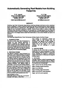
Avida [14] is an evolutionary computation platform in which self-replicating digital organisms evolve in a fashion with more parallels to natural evolution than other forms of evolutionary computation (e.g., genetic algorithms and genetic programming). Specifically, whereas other evolutionary computation approaches evaluate each individual in the population and explicitly select individuals to move to the next generation, the evolution of digital organisms is more open-ended. The organisms are asynchronously evaluated; if an organism exhibits desirable behavior, then the relative amount of resources that the organism receives is increased. Because the evaluation is not used to explicitly select organisms to survive, poorly performing organisms may continue to exist in the population and could eventually produce a novel solution. Until recently, Avida has been used primarily to study biological evolution [14]. Figure 1 depicts an Avida population and the structure of an individual organism. Each digital organism comprises a circular list of instructions (its genome) that is executed atop its virtual CPU. The Avida instruction set is designed so that random mutations will always yield a syntactically correct program, albeit one that may not perform any meaningful computation. An Avida environment comprises a number of cells, where a cell is a compartment in which an organism can live. Each cell can contain at most one organism, and the size of an Avida population is bounded by the number of cells in the environment. 1
Avida is a digital evolution platform used to study biological evolution [14].
4
Organisms are self-replicating, that is, the genome itself must contain the instruction to create an offspring. Random mutations are introduced during replication. Mutation types include: replacing the instruction with a different one, inserting an additional, random instruction into the offspring’s genome, and removing an instruction from the offspring’s genome. For Avida-MDE, a mutation might change the label on a state diagram transition. When an organism replicates, a cell to contain the offspring is selected from the environment, and any previous inhabitant of the target cell is replaced (killed and overwritten) by the offspring. Legend organism cell
p sub p sub k shift−r h push q nand e if−less b nop−B C rotate−r m inc s h−alloc t h−divide a nop−A y get−head o add e if−less y get−head A set−flow z if−label F get−id c nop−C D send−msg i swap−stk v h−search E retrieve−msg F get−id f if−grt w mov−head z if−label u h−copy u h−copy u h−copy D send−msg u h−copy D send−msg z if−label u h−copy C rotate−r
send−msg
Registers AX BX CX
CPU
Heads Instruction Flow−control Read Write
Cell Interface
Stacks GS LS
Fig. 1. Elements of AVIDA platform Developers use tasks to describe desirable organism behavior. For example, we define a task that evaluates whether the generated behavioral models satisfy functional properties (e.g., invariant safety-critical properties). Performing a task increases an organism’s merit, which determines how many instructions its virtual CPU is allowed to execute relative to the other organisms in the population. For example, an organism with a merit of 2 will, on average, execute twice as many instructions as an organism with a merit of 1. Because the population has a fixed maximum size, to have the best chance of surviving in the population, an organism must have as much merit as its peers. This competition for survival ensures that, over time, the population comprises organisms that increasingly satisfy more tasks. 2.2
Model-Driven Engineering for Dynamically Adaptive Systems
To provide context for our approach, we briefly describe the model-driven engineering process (depicted in Figure 2) for constructing a DAS [16]. At the Goal phase, the functional goals (e.g., Goal) of the dynamically adaptive system are identified [16]. At the Requirements phase, the domains (Di and Dj ), i.e., environmental conditions, and invariants (INV) of the DAS are identified. Additionally, adaptations among these domains are captured as dotted-line arrows. At the Design Models phase, design models (e.g., Mi , Mj , Mij , Mji ) are constructed, where Mi and Mj represent designs for target systems, and Mij and Mji are design models capturing the behavior of the system during adaptation, where all of the models satisfy the invariants (INV). Each of the design models has a set of latent functional properties (e.g., LFi , LFj , LFij ) and non-functional characteristics (e.g,. NFi , NFj , NFij ) that make it more suitable for a specific domain. At the Implementation phase, code can be automatically generated from the design models using code generators.
5 Goal
Goals Di
...
...
Dj
...
Requirements LFi , NFi
Design Models
Mi
LFij , NFij M ij M ji
LFi , NFi Mj
INV
...
Implementation
Fig. 2. MDE Process for a DAS In this paper, we describe an approach to generating design models, Mi , of target systems. Each design model Mi should minimally satisfy INV, but it may also exhibit non-functional characteristics (NFi ) and latent functional properties (LFi ), all of which collectively make the behavior of Mi particularly well-suited to handle domain Di . As a means to address uncertainty in execution environments, our approach also helps to discover additional domains based on viable, but not previously specified combinations of environmental conditions.
3
Approach
To address uncertainty within the development of DASs, we propose a four step process with corresponding digital evolution-based tool support. We illustrate our approach using GridStix, an adaptive flood warning system [15]. 3.1
Running Example: An Adaptive Flood Warning System
GridStix is an adaptive flood warning system deployed to monitor the River Ribble in Yorkshire, England [15]. Floods are an increasing and costly problem faced by the United Kingdom. The amount of damage caused by a flood is correlated with both the depth of the water and the amount of time between the flood prediction and the flood. GridStix is a light-weight grid-computing flood monitoring system that comprises a set of nodes (e.g, A-E and N). Figure 3 provides an overview of GridStix and an elided portion of the corresponding object diagram. For this case study, we generate models that represent the target systems of one Node (N). A Node monitors the status of the river using its PressureSensor (depth sensor) and DigiCamSensor (digital camera river flow speed sensor). The node then queries an additional UpstreamNode (A) and uses the information from the UpstreamNode and the depth and speed it sensed to make a prediction. Lastly, the node transmits the prediction to a neighboring node (B, C, or D) that forwards it to a gateway node (E) that is connected to a modem and is responsible for sending the predictions off-site for additional processing. Three potentially conflicting non-functional objectives of a node are: (1) energy efficiency (EE) because a node has a limited power supply, (2) fault-tolerance (FT) because a node is deployed remotely, and (3) prediction accuracy (AC) because a node should avoid failures or false alarms. A node is able to adapt its behavior in a number of different ways that affect its non-functional attributes. In this case
6
study, we enable a node to dynamically change its CPU speed, select a different routing algorithm to transmit information, e.g., shortest path (N→B→C→D→E) vs. fewest hop (N→D→E), and use a different physical network infrastructure to transmit predictions (e.g., bluetooth, wireless, GPRS – General Packet Radio Service, a packet-based wireless communication service). transmits
River Ribble B A
FewestHopNode C
D
E
1 prediction 1 1 queries depth 1
Node
N
transmits prediction 1
A − D: neighboring nodes E: gateway node
N: current node river flow
1
1
1
1
ShortestPathNode
a. Node Depoyment
PressureSensor
queries speed 1
queries depth
1
queries speed
1
DigiCamSensor UpstreamNode
b. Elided Object Diagram
Fig. 3. GridStix Application 3.2 Process Figure 4 provides a graphical depiction of our approach, where shading levels indicate different combinations of functional properties and non-functional characteristics. In the following, we provide additional detail about how the process addresses uncertainty within the development of DASs. D 1A
D1
D3
D3
D 1B D2
D2 NF i
LFi , NFi
Mi (1) Generate models (Mi) with non−functional characteristics (NFi).
D2
Mi (2) Cluster by domain (Di) using utility functions
(3) Identify latent functional properties (LFi)
(4) Select target system models for each domain.
Fig. 4. Approach overview Step 1: Generate models with non-functional characteristics. The model generation step addresses the uncertainty present in the unknown environment of the DAS. Specifically, Avida-MDE generates a suite of models (e.g., Mi ), each of which minimally satisfy the developer-specified invariants (INV), but may also contain additional behavior that makes it suitable for domains that were not explicitly provided. The developer provides the following inputs: – UML Class/Object Diagram: The UML class/object diagram (e.g., a detailed version of Figure 3 b.) describes the structure of the system including the classes, attributes, operations, associations, and possible attribute values. This information is used by Avida-MDE to construct state diagram elements.
7 – UML State Diagrams: For each class/object, the developer may optionally provide a state diagram describing existing behavior. In general, Avida-MDE can be used to generate new state diagrams or extend existing state diagrams [17]. – Invariants: Invariant functional properties (INV) describe the desired behavior of the generated models. For example, a GridStix functional property is “Globally, it is always the case that if a node makes a prediction, then eventually the node will transmit the prediction to one of its neighbors.” – Scenarios: Scenarios describe the possibilities for target system behavior. To account for the uncertainty in the execution environment, the developer specifies a set of required functional scenarios that must be supported by the generated models. Additionally, the developer specifies a set of non-functional based scenarios, where each one of the non-functional based scenarios specifies a different way to achieve the same functional objective (i.e., send prediction) with differing nonfunctional characteristics (i.e., send prediction using GPRS). One scenario from the non-functional based scenarios set must be supported by a generated model. For example, Figure 5 depicts a set of two non-functional based scenarios and one required scenario for the GridStix system. The two non-functional based scenarios both set the CPU speed and query the PressureSensor. However, each scenario sets the CPU speed to different values and thus affects both energy efficiency (i.e., running slower conserves battery power) and accuracy (i.e., running faster is more accurate). The required scenario probes the DigiCamSensor. :Node
:PressureSensor
:DigiCamSensor
Required scenario
Non−functional based scenario set
Comments Energy Efficient: FT=0, EE=1, AC=0 Set CPU to 100 and query the PressureSensor to obtain depth measurement. Balanced: FT=0, EE=.5, AC=.5 Set CPU to 200 and query the PressureSensor to obtain depth measurement. Required: FT=0, EE=0, AC=0 Query the DigiCamSensor to obtain speed measurement.
CPUSpeed:=100 []/getDepth() setDepth()
CPUSpeed:=200 []/getDepth() setDepth() []/getSpeed() setSpeed()
Fig. 5. GridStix Scenario Diagrams At a high level, the use of non-functional based scenarios enable AvidaMDE to generate innovative behavioral models that address previously unspecified combinations of environmental conditions by integrating the behavior represented by all or parts of the non-functional based scenarios, required scenarios, and some additional behavior in such a way that the invariants are satisfied. Step 2: Cluster by domain using utility functions. To assist the developer in leveraging non-functional trade-offs between the models to address changing environmental conditions, we provide an automated means to cluster the generated models by a high-level description of the domains provided by the developer. Moreover, our key insight is that for each known high-level domain, a developer
8
has a set of non-functional preferences that reflect their understanding of the domain’s environmental conditions and can be used to identify a domain model set, a set of models whose non-functional characteristics make it suitable for a domain. For a given domain, Di , we capture the developer’s non-functional preferences using a utility formula [18]. The domain model set for a given domain comprises a set of models that maximize the utility function, but do so using different trade-offs between non-functional characteristics. For example, the GridStix developers previously identified three high-level domains [15]: (1) normal conditions, (2) increased flow, and (3) flood. For the normal conditions, because the river is calm and a flood is unlikely, energy efficiency may be more important than fault-tolerance or accuracy, as captured by the following utility formula: 0.6∗EE + 0.2∗ FT + 0.2∗ AC. Similarly, utility formulae are specified for the increased flow and flood domains. These utility formulae are used to cluster the generated models by domain. Models whose utility function evaluation are below a given threshold do not reflect useful behavior, and hence are not an element of any domain model set and are therefore discarded. The coloring in Figure 4 indicates the non-functional characteristic differences between the models; as such, the models with lighter coloring are clustered in domain model set D1 , the models with moderate coloring are clustered for domain D2 , and the models with darker coloring are clustered for domain D3 . Step 3: Identify latent functional properties. Within a domain model set, all of the models satisfy the invariants (INV), and their respective non-functional characteristics (NFi ) satisfy the developer’s utility function for the domain (Di ). To further distinguish the models within a domain model set, we provide an automated approach to discovering their latent functional behavior (e.g., LFi ). Avida-Marple [19] is a digital-evolution based tool that we previously developed to discover latent temporal logic properties. Within Avida-Marple, digital organisms generate properties by instantiating the five most commonly occurring specification patterns [20] in the form of Linear Temporal Logic (LTL). The pattern placeholders are instantiated with boolean propositions created using class attribute and operation information from the class diagram (specified also as an input to Avida-MDE). During the Avida-Marple evolutionary process, organism mutations produce different LTL properties that may be satisfied by the UML model. Natural selection gives rise to a population of organisms that produce increasingly more relevant properties, where relevancy can refer to a type of property or the use of a specific attribute or operation. For the GridStix case study, we considered stronger properties more relevant because they revealed more information about the model; here, stronger means those properties that made stronger claims, such as universality, or those that contained conjunctive expressions. In essence, Avida-Marple discovers latent functional properties that developers may not otherwise specify or even consider. These latent functional properties may uncover unwanted behavior that could either be used to refine the requirements for generation or disqualify a model from representing a target system. For easier readability, these latent functional properties are presented to the developer in natural language [21].
9
Step 4: Select target system models for each domain. Using the nonfunctional characteristics and the latent functional properties, the developer identifies one or more models within each domain model set to use as a target system. This step has three parts. First, the developer eliminates models that have unwanted latent functional behavior (LFi ). Second, the developer infers sub-domains, which are a fine-grained set of environmental conditions, from the generated models; these combinations of environmental conditions were not explicitly specified by the developer. While all of the generated models within a domain model set satisfy the utility function, it is possible, that they do so with significantly different parameter values. As such, a sub-domain is created for each cluster of parameter values. For example, within the Flood conditions domain, we identified two sub-domains that describe Node behavior when a neighboring node is submerged and when it is not submerged. Therefore, the identification of sub-domains addresses uncertainty in the execution environment by enabling the developer to identify combinations of environmental conditions that may not otherwise have been considered. In cases where there are no obvious sub-domains, then we consider that domain to be a simple domain. Third, the developer selects one model within each simple domain or sub-domain to use as a target system. These selected models can be incorporated into the model-driven engineering process for DASs as inspiration for a human created model, manually modified and then used to generate code, or used to generated code directly.
4
Using Digital Evolution to Generate Models
Avida-MDE enables developers to generate innovative behavioral models for target systems. Specifically, mutations produce behavioral models that developers might not otherwise discover, while natural selection pressures organisms to generate models that meet developer requirements, i.e., invariants. This blend of innovation and requirements satisfaction is especially pertinent for generating target systems that must respond to varying environmental conditions in a resilient and robust fashion. In previous work [17], we developed a preliminary version of Avida-MDE to generate behavioral models, but did not address non-functional model characteristics or look for latent properties to differentiate models. In the following, we describe the three major ways in which we extended the Avida platform to create Avida-MDE. Configuration. Avida-MDE accepts the four configuration inputs specified by the developer, i.e., UML class diagram, UML state diagrams, invariants, and scenarios. These inputs serve three purposes: (1) The invariants and scenarios are requirements for the behavioral models. (2) The UML state diagrams describe existing behavior to be extended through generation. (3) The UML class diagram and scenario diagram provide the alphabet from which state diagram transitions are created. Specifically, for each scenario, the messages form a list of transition labels. In addition, for each class, a list of triggers (operations), a list of guards (expressions built using attributes), and a list of actions (the operations of classes related to it via associations) are extracted. Because the Avida-MDE alphabet includes triggers, guards, and actions (described by the
10
class diagram), organisms are able to generate additional and potentially more interesting viable transitions, not otherwise considered by the developer. New Instructions. To enable organisms to manipulate state diagrams, we developed a new set of Avida instructions that are reusable across all DAS applications specified by the configuration step. Figure 6 describes the instructions and their use. The selection instructions {1-3} use different strategies for selecting alphabet elements to use to create a transition. The internal representation of an organism’s alphabet is lists of states, transition labels, triggers, guards, and actions. Each list has an index that initially points to the first list element. (The list of states has two indices – one for the origin state and one for the destination state.) An organism selects an alphabet element by having the list index point to it. Instruction {4} is used to add the transition described by the current origin state, destination state, and transition label. Instruction {5} is used to add the transition described by the current origin state, destination state, trigger, guard, and action. Instructions {6-7} are used to add transitions in a loop. No. Name {1} next-{orig, dest, tl, tr, gu, act} {2} move-rel-{orig, dest, tl, tr, gu, act} {3} move-abs-{orig, dest, tl, tr, gu, act} {4} addTransL {5} addTransT {6} start-loop {7} end-loop
Instruction Use Move the index forward one list element. Move the index forward a number of list elements. Move the index forward an absolute number of list elements from the beginning of the list. Create a transition using the transition label. Create a transition using a trigger, guard, and action. Start creating a list of transitions that form loop. Use the list of transition labels to create a loop.
Fig. 6. Avida-MDE Instructions Excerpted New Tasks. We defined a set of tasks to reward Avida organisms for generating a behavioral model that meets the developer-specified invariants and scenarios. Prior to replication, an organism and the model that it generates are evaluated by the tasks. An organism that performs these tasks will have a better chance of survival and will eventually dominate the population. The scenario task (checkScenario) rewards an organism for generating a model that supports key scenarios defined by the developer. For each scenario, the developer must specify the messages between objects and may optionally include a start state for each object and specify whether the scenario should iterate. The reward for a required scenario is the percentage of the execution path supported by the state diagrams. Additionally, the reward for a non-functional based scenarios set is the largest percentage of any of the scenarios in the set supported by the state diagrams. For example, using the non-functional based scenarios set in Figure 5, if an organism generated a behavioral model that supported 67% of the Energy Efficient scenario and 33% of the Balanced scenario, then the reward for this non-functional based scenarios set would be 67% of the reward value.
11
A property task (checkProperty) rewards organisms that generate state diagrams that adhere to a formally specified property. These tasks constrain the behavior of the interacting state diagrams. To enable Avida-MDE to determine if the generated state diagrams satisfy a stated property, we extended Avida to use external third party tools. Specifically, the checkSyntax task uses Hydra, an existing UML formalization engine [22], to translate a UML model into Promela, the specification language for the model checker Spin [23]. Next, the checkWitness task uses Spin to verify that at least one execution path (i.e., a witness trace) through the Promela model satisfies the functional property specified by the developer in Linear Temporal Logic (LTL) [24]. Lastly, if the checkWitness for a given property passes, then the checkProperty task uses Spin to verify that the Promela specification satisfies the same functional property. Additional details on the external and previously developed analysis process can be found in [22].
5
Case Study
In this section, we provide further details about applying our approach to GridStix and discuss our results. The objective of our case study is to generate target systems that describe the behavior of the Node object as it interacts with its sensors, queries an upstream node, makes a prediction regarding the state of the river, and transmits information to a neighboring node. Step 1: Generate models with non-functional characteristics. To use Avida-MDE to generate target systems for GridStix, we provided the following: – A version of the UML Object diagram (in Figure 3 b.) including operations, attributes, and possible attribute values to be used for the organism alphabet. – Functional invariant(s): “Globally, it is always the case that if a node makes a prediction, then eventually this prediction is transmitted to either its shortest path neighbor or its fewest hop neighbor.” This invariant is checked by the checkSyntax, checkWitness, and checkProperty tasks. – State diagrams describe the behavior of all of the classes except Node. Because our case study focuses on the behavior of Node, these other state diagrams will not be extended by Avida-MDE. – Three required functional scenarios describe: (1) querying the Node’s DigiCam to monitor the speed of the river, (2) querying the depth sensed by the UpstreamNode, and (3) querying the speed sensed by the UpstreamNode. Additionally, we specified two sets of non-functional based scenarios. The first set provides three computational speed alternatives (two of which are depicted in Figure 5). The second set provides six alternative ways to send data. The messages defined by these scenarios were used as a portion of the organism alphabet. Additionally, a checkScenario task was used to reward organisms for supporting the scenarios.
Using these inputs, forty Avida-MDE experiments were run in parallel to account for the stochastic nature of the evolutionary process. All of the experiments ran for 10 hours on a high-performance computing center; we started the experiments at the end of a work day and the results were available by the beginning of the next work day. In total, 779 unique models were generated. Step 2: Cluster by domain using utility functions. Next, to manage the non-functional trade-offs, we partitioned the generated models into three domain
12
model sets, one for each of the three high-level domains from the developer (i.e., normal conditions, increased flow, and flood). Specifically, we first specified a utility function for each domain: – Normal conditions utility = 0.6∗EE + 0.2∗FT + 0.2∗AC. We prefer that the nodes are energy efficient to preserve battery life. – Increased flow utility = 0.33∗EE + 0.34∗FT + 0.33∗AC. We prefer that the nodes are a balance of fault-tolerant, accurate, and energy efficient. – Flood utility = 0.2∗EE + 0.0∗FT + 0.8∗AC. We prefer that the nodes are accurate because the conditions are critical.
We then selected models that maximize the respective utility formula of each domain. Specifically, we selected 3 models from the normal conditions domain model set, 2 models from the increased flow conditions domain model set, and 3 models from the flood conditions domain model set. These models will be further evaluated to identify latent properties and possible sub-domains. Step 3: Identify latent functional properties. Next, we used AvidaMarple to identify the latent functional behavior of the 8 selected models. For example, three of the discovered latent properties for one of the models in the normal conditions domain model set are: 1. Globally, it is always the case that if Node.CPUSpeed < 100 holds, then FewestHopNode.received == 0 eventually holds. 2. Globally, it is always the case that if Node.CPUSpeed > 200 holds, then FewestHopNode.received == 1 eventually holds. 3. Globally, it is always the case that if FewestHopNode.sendPredictionUsingGPRS() holds, then ShortestPathNode.received == 1 eventually holds. These three properties together specify that the Node always sends its prediction to the ShortestPathNode, but also sends its prediction to the FewestHopNode if the CPUSpeed is greater than 200. This behavior implies that the Node is generally energy efficient (sending to the ShortestPathNode), but also has some innate faulttolerance that is achieved by sending to the FewestHopNode only when the CPU
speed is running quickly. Step 4: Select target system models for each domain. Using the latent functional behavior identified as part of Step 3, we noted that 2 of the 8 models selected from the three domain model sets contained unwanted latent behavior. Thus, we eliminated them. The two models in the Increased Flow domain model set achieved the same utility value using similar non-functional characteristics; neither had unwanted latent behavior. To minimize model complexity, we selected the model with the fewest transitions. We repeated this evaluation process for the Flood domain model set, which also had two similar models. For the normal conditions domain model set, the two generated models satisfied their utility function similarly, but with differing non-functional characteristics. Specifically, based on the utility function parameters, we identified two sub-domains, where one sub-domain was more energy efficient and the other sub-domain was more fault-tolerant. The latent functional properties discovered for these two models reaffirmed our identification of sub-domains and explained why the models had differing non-functional characteristics. For example, the latent functional properties for the normal conditions - fault-tolerant sub-domain were previously described and indicate that it transmits predictions to both its
13
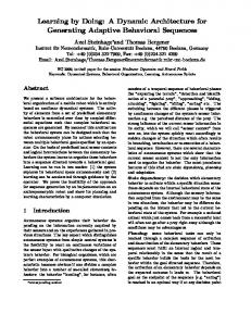
shortest path and its fewest hop neighbor. Thus far, we have focused on functional and non-functional properties to illustrate the differences between the models generated by Avida-MDE to satisfy the same invariant requirements. These differences are, in fact, due to both the different transitions (i.e., guards, triggers, actions) that get generated for each diagram, as well as the different topological structures of the diagrams (e.g., number of states, number of transitions, the connectivity between states, etc.). For example, Figure 7 highlights the amount of variation present in our generation process by depicting the varying topologies of the four generated models selected as target systems A
B
Increased Flow
Flood
C
Normal Conditions − fault−tolerant
D
Normal Conditions − energy efficient
Fig. 7. Generated Target Systems
6
Related Work
While there has been significant progress in synthesizing state diagrams from scenarios and/or properties, to the best of our knowledge, our approach is the only one to generate multiple solutions (in the form of models) for interacting objects, while considering functional properties and non-functional characteristics. In general, scenario-based synthesis techniques [7–11] accept a set of scenarios (i.e., a sequence diagrams) as input and produce a set of communicating state diagrams as output. The sequence diagram messages form the alphabet. Property synthesis techniques establish a one-to-one mapping between a formally specified property and a state diagram [12, 25, 26], where each state diagram represents all possible behaviors that satisfy the property. Our approach addresses the uncertainty present in the development of DASs and thus differs from the synthesis approaches in three key ways: First, in addition to the alphabet formed by the scenario messages, Avida-MDE also uses an evolving alphabet that is created by combining the triggers, guards, and actions inferred from the class diagram (described in Section 4). One ramification of this alphabet is that Avida-MDE generates different transitions than those generated from the alphabets of other approaches. As a result, the generated behavioral model has the potential to be less intuitive and perhaps offer more resiliency than those created with traditional techniques. Second, in contrast to the synthesis approaches, Avida-MDE generates a suite of behavioral models that all satisfy the functional invariant, but have differing latent functional properties and non-functional characteristics. Third, to assist the developer in performing trade-off analysis, our approach clusters the models by non-functional preferences for a domain, identifies the latent functional properties, and infers sub-domains that identify unspecified combinations of environmental conditions.
7
Discussion
In this paper, we have presented an approach to addressing environmental uncertainty with a digital-evolution based approach to generating models for the development of a DAS. Next, we reflect upon our technique and provide suggestions for using it as part of the development process. It is possible to scale Avida-MDE to larger applications by increasing the length of the organism genome, increasing the number of organisms in a population, or by increasing the number of experiments run. Additionally, the performance of Avida-MDE is dependent upon many factors including the size of the model, number of experiments run, duration of experiments, and available computational resources. To use our approach effectively, developers should focus on describing what the DAS should do, rather than how the DAS should achieve this behavior. This strategy enables Avida-MDE organisms to generate innovative models that comply with developer requirements. However, determining the appropriate level of detail for the developer-specified requirements is frequently an iterative process (as is the case with traditional development techniques). If Avida-MDE generates too few models, then the topology information as specified by the scenarios should be relaxed. However, if Avida-Marple discovers unwanted latent behavior common to all of the generated models, then the invariant and/or scenario requirements should be refined. Numerous directions for future work are possible. One possibility is to explore how digital-evolution based techniques can be used to identify the quiescent states, or states within the target system from which the DAS can adapt safely [27]. A second possibility is to enable organisms to instantiate design patterns and thus potentially create more modular and extensible designs. Another possibility is to use Avida-MDE to generate the adaptation logic (e.g., Mij , Mji ) that describes how the DAS transitions between target systems.
Bibliography [1] Schmidt, D.C.: Model-Driven Engineering. IEEE Computer 39(2) (2006) [2] McKinley, P., Cheng, B.H., Ofria, C., Knoester, D., Beckmann, B., Goldsby, H.: Harnessing digital evolution. IEEE Computer 41(1) (2008) 54–63 [3] Garlan, D., Cheng, S.W., Huang, A.C., Schmerl, B., Steenkiste, P.: Rainbow: Architecture-based self-adaptation with reusable infrastructure. Computer 37(10) (2004) 46–54 [4] Gorlick, M.M., Razouk, R.R.: Using weaves for software construction and analysis. In: ICSE ’91: Proceedings of the 13th International Conference on Software Engineering, Los Alamitos, CA, USA, IEEE Computer Society Press (1991) 23–34 [5] Magee, J., Dulay, N., Eisenbach, S., Kramer, J.: Specifying Distributed Software Architectures. In Schafer, W., Botella, P., eds.: Proc. 5th European Software Engineering Conf. (ESEC 95). Volume 989., Sitges, Spain, Springer-Verlag, Berlin (1995) 137–153 [6] Oreizy, P., Medvidovic, N., Taylor, R.N.: Architecture-based runtime software evolution. In: ICSE ’98: Proceedings of the 20th International Conference on Software Engineering, Washington, DC, USA (1998) 177–186 [7] Whittle, J., Jayaraman, P.K.: Generating hierarchical state machines from use case charts. In: 14th IEEE International Requirements Engineering Conference (RE’06), Washington, DC, USA (2006) 16–25
15 [8] Harel, D., Kugler, H., Pnueli, A.: Synthesis revisited: Generating statechart models from scenario-based requirements. In: Formal Methods in Software and Systems Modeling. (2005) [9] Kruger, I., Grosu, R., Scholz, P., Broy, M.: From MSCs to statecharts. In DIPES’98. Kluwer. (1999) [10] Alur, R., Etessami, K., Yannakakis, M.: Inference of message sequence charts. IEEE Trans. Softw. Eng. 29(7) (2003) 623–633 [11] Uchitel, S., Brunet, G., Chechik, M.: Behaviour model synthesis from properties and scenarios. In: ICSE ’07: Proceedings of the 29th International Conference on Software Engineering. (2007) 34–43 [12] Jobstmann, B., Bloem, R.: Optimizations for LTL synthesis. In: FMCAD ’06: Proceedings of the Formal Methods in Computer Aided Design. (2006) [13] Piterman, N., Pnueli, A., Sa’ar, Y.: Synthesis of reactive(1) designs. In: Conference on Verification, Model Checking, and Abstract Interpretation. (2006) 364–380 [14] Ofria, C., Wilke, C.O.: Avida: A software platform for research in computational evolutionary biology. In: Journal of Artificial Life. Volume 10., International Society of Artificial Life (ISAL) (March 2004) 191–229 [15] Hughes, D., Greenwood, P., Coulson, G., Blair, G., Pappenberger, F., Smith, P., Beven, K.: An intelligent and adaptable flood monitoring and warning system. In: Proceedings of the 5th UK E-Science All Hands Meeting (AHM) (Best Paper Award). (2006) [16] Zhang, J., Cheng, B.H.C.: Model-based development of dynamically adaptive software. In: ICSE ’06: Proceeding of the 28th International Conference on Software Engineering. (2006) 371–380 [17] Goldsby, H.J., Cheng, B.H.C., McKinley, P.K., Knoester, D.B., Ofria, C.A. In: Proceedings of the 5th International Conference on Autonomic Computing (ICAC 2008), Chicago, Illinois (To appear). [18] Cheng, S.W., Garlan, D., Schmerl, B.: Architecture-based self-adaptation in the presence of multiple objectives. In: ICSE 2006 Workshop on Software Engineering for Adaptive and Self-Managing Systems, Shanghai, China (May 2006) [19] Goldsby, H.J., Cheng, B.H.C.: An automated approach to detecting unwanted latent behavior in models of high assurance systems. Technical report, Michigan State University (May 2008) (submitted for publication). [20] Dwyer, M.B., Avrunin, G.S., Corbett, J.C.: Patterns in property specifications for finite-state verification. In: Proceedings of the 21st International Conference on Software Engineering. (1999) 411–420 [21] Konrad, S., Cheng, B.H.C.: Facilitating the construction of specification patternbased properties. In: Proceedings of the IEEE International Requirements Engineering Conference (RE05), Paris, France (August 2005) [22] McUmber, W.E., Cheng, B.H.C.: A general framework for formalizing UML with formal languages. In: Proceedings of the IEEE International Conference on Software Engineering (ICSE01), Toronto, Canada (May 2001) [23] Holzmann, G.: The Spin Model Checker, Primer and Reference Manual. AddisonWesley (2004) [24] Konrad, S., Goldsby, H., Lopez, K., Cheng, B.H.C.: Visualizing requirements in UML models. In: Proceedings of the International Workshop on Requirements Engineering Visualization (REV 2006) as part of (RE’06). (September 2006) [25] Kazhamiakin, R., Pistore, M., Roveri, M.: Formal verification of requirements using spin: A case study on web services. In: SEFM ’04: Proceedings of the Software Engineering and Formal Methods. (2004) 406–415 [26] Van, H.T., van Lamsweerde, A., Massonet, P., Ponsard, C.: Goal-oriented requirements animation. In: Proceedings of RE’04, 12th IEEE Joint International Requirements Engineering Conference. (2004) [27] Zhang, J., Yang, Z., Cheng, B.H., McKinley, P.K.: Adding safeness to dynamic adaptation techniques. In: Proceedings of ICSE 2004 Workshop on Architecting Dependable Systems, Edinburgh, Scotland, UK (May 2004)