2013 International Conference on Indoor Positioning and Indoor Navigation, 28th -31st October 2013
Bluetooth Embedded Inertial Measurement Unit for Real-Time Data Collection for Gait Analysis Ravi Chandrasiri Department of Electrical and Computer Engineering Sri Lanka Institute of Information Technology Colombo, Sri Lanka
[email protected]
Nimsiri Abhayasinghe Department of Electrical and Computer Engineering Curtin University Perth, Western Australia
[email protected]
Abstract—Inertial Measurement Units (IMUs) are often used to measure motion parameters of human body in indoor/outdoor localization applications. Most of commercially available low-cost IMUs have limited number of sensors and are often connected to a computer by a wired connection (usually by USB). The disadvantage of using wired IMUs in human gait measurement is that, the wires disturb the natural gait patterns. The existing IMUs with wireless connectivity solve that problem, but are relatively high cost. This paper describes the development and testing of a miniature IMU that can be connected to a Windows based computer or an Android based mobile device through Bluetooth. The IMU consists of a 3-axis accelerometer, 3-axis gyroscope, 3-axis magnetometer, a temperature sensor, a pressure sensor and an ambient light sensor. Sensors are sampled at a frequency configurable by the user with a maximum set at 100 Hz. Raw sensor data are streamed through the integrated Bluetooth module to the host device for further processing. The IMU is also equipped with a microSD card slot that enables on-board data logging. The power usage of the Bluetooth transmitter is optimized because only the sampled sensor data are transmitted. The windows application can be used to view sensor data, plot them and to store them into a file for further processing. Android application can be used to view data as well as to record data into a file. The small size of the device enables it be attached to any part of lower or upper human body for the purpose of gait analysis. Comparison of the performance of the device with a smartphone indicated that the output of the IMU is comparable to the output of smartphone. Index Terms—indoor localization; IMU; 3-axis inertial sensors; human gait analysis
I. I NTRODUCTION Inertial Measurement Units (IMU) are often used in indoor/outdoor localization applications and robotic applications to measure inertial parameters of human body or the robot. Most of commercially available low-cost IMUs are wired to a computer usually using USB [1]. IMUs with wireless connectivity to a computer are costlier [1], [2]. Commercially available IMUs are usually equipped with a 3-axis accelerometer, a 3-axis gyroscope and a 3-axis magnetometer but they do not include an ambient light sensor or a barometer [1], [2] that may also be important in indoor localization applications as the ambient light sensor may be used to detect different light levels in different areas and the barometer to identify different floor levels. A temperature sensor may also be important in indoor c 978-1-4673-1954-6/12/$31.00 2012
Iain Murray Department of Electrical and Computer Engineering Curtin University Perth, Western Australia
[email protected]
localization applications to detect different temperature levels in different areas (e.g. higher temperature around fire place) and are sometimes included in commercially available IMUs for the purpose of temperature compensation of inertial sensors [1]. The IMU discussed in this paper consists of an accelerometer, a gyroscope, a magnetometer, a temperature sensor, an ambient light sensor and a barometer. This IMU was developed as a part of an indoor navigation system for vision impaired people. Features of two commercially available IMUs with wireless connectivity and their prices are compared in “Related Work” section and the development of the IMU, its hardware/software features and performance are discussed in “Construction of the IMU” and “Performance of the IMU” sections. II. R ELATED W ORK A series of IMUs have been developed by YEI Technologies with different features [1]. All these IMUs are equipped with a 14-bit 3-axis accelerometer, a 16-bit 3-axis gyroscope and a 12-bit 3 axis magnetometer. Key technical details of these are shown in Table I. They also include a temperature sensor that is used for temperature compensation of inertial sensors. The cheapest of them (US$ 163) that comes as a standalone IMU, has USB and RS232 connectivity only whereas the others that have wireless connectivity are costlier (US$ 304 for Bluetooth version and US$ 247 for Wireless 2.4 GHz DSSS version). The version with on-board data logging (US$ 202) has USB connectivity only. The processor in all these devices is a 32-bit RISC processor running at 60 MHz. Two data modes, IMU mode and Orientation mode, are available in all these versions. Kalman filtering, Alternating Kalman filtering, Complementary filtering or Quaternion Gradient Descent filtering can be selected as orientation filter when not in IMU mode where processed orientation is made available as the output. A maximum sampling rate of 800 Hz is available in IMU mode. The IMU of x-io Technologies [2] is equipped with a 12-bit 3-axis accelerometer, a 16-bit 3-axis gyroscope and a 12-bit 3-axis magnetometer of which the key technical details are given in Table I. This IMU too, has a temperature sensor for temperature compensation of inertial sensors. It has a maximum
2013 International Conference on Indoor Positioning and Indoor Navigation, 28th -31st October 2013 Table I T ECHNICAL D ETAILS OF IMU S OF YEI T ECHNOLOGIES AND X - IO T ECHNOLOGIES Sensor
Parameter Bit size Max. Range Bit size Max. Range Bit size Max. Range
Accelerometer Gyroscope Magnetometer
YEI Technologies 14 bits s´8 g 16 bits s´2000 o /sec 12 bits s´8.1 G
x-io Technologies 12 bits s´8 g 16 bits s´2000 o /sec 12 bits s´8.1 G
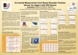
sampling rate of 512 Hz and has USB, Bluetooth and UART connectivity as well as SD card slot for on-board data logging. This device has an IMU algorithm and Attitude and Heading Reference System (AHRS) algorithm running on-board for realtime orientation calculations. The price of this device is £ 309 (~US$ 460). III. C ONSTRUCTION OF THE IMU A. Architecture The IMU discussed in this paper consists of a 13-bit 3-axis accelerometer, a 16-bit 3-axis gyroscope, a 12-bit 3-axis magnetometer, a 12-bit temperature sensor, a 19-bit barometer sensor and a 16-bit ambient light sensor. It is equipped with a USB port and a Bluetooth module to communicate with a computer and an SD card slot for on-board data logging. The processor used in the IMU is an 8-bit AVR microcontroller running at 8 MHz on a 3.3 V supply. This microcontroller is a cheaper low power (~10 mW at 8 MHz on 3.3 V [5]) processor, yet powerful enough to cater the requirements of the IMU. Observations of [3] and [4] indicate that normal gait frequency is approximately 2 steps·s−1 and fast gait frequency is approximately 2.5 steps·s−1 and hence, 100 Hz sampling rate is sufficient to extract features of human gait using inertial sensors and the maximum sampling rate of the IMU was selected as 100 Hz. Fig. 1 shows the architecture of the IMU. Raw sensor data collected are first scaled appropriately (as different scales are available for most of the sensors) and then they are organized into frames as discussed under “Data Acquisition and Transmission” section. These frames are streamed out through USB 2.0 interface and Bluetooth interface without any further processing. The scope was to present sensor data to the user without performing complex computations, so that the flexibility is given to the user to perform any computations/analysis with these data in an external processing device: either a personal computer or a smartphone. This avoids any “unknown” on-board data processing to be there which keeps full control to the user. B. Sensors All the sensors have digital data output with I2 C interface. Vendor details, bit size, resolution and maximum range of each sensor are shown in Table II. All these sensors have technical specifications comparable with sensors used in [1] and [2]. Because all sensors have output data width of 16 bits or less (except for barometer which has both 16 and 19-bit modes),
Figure 1. Architecture of the IMU
for uniformity all sensor data were converted to 16-bit format so that manipulation of data is easier.
C. Data Acquisition and Transmission Although the accelerometer, gyroscope and magnetometer are sampled at 100 Hz, the barometer, light sensor and temperature sensor need not to be sampled at a high rate; hence they are sampled at 20 Hz. With these sampling rates, two types of data frames are created according to the availability of sensor data. The first type of data frame consists of all sensor data while the second consists of accelerometer, gyroscope and magnetometer only. Fig. 2 depicts the two frame patterns in the actual sequence of data. Transmission time for each 3-axis sensor was taken as 1 ms, so that the data transmission rate of 48 kbits·s−1 is sufficient, which is well below the Bluetooth bandwidth. However, as the communication with the Bluetooth module is via UART, the limitations of UART limits the practical baud rate and the baud rate was set as 115.2 kbits·s−1 to achieve reliable communication. It should also be noted that there are data losses in practice and time to recover/retransmit such packets has to be accommodated. As the data of sampled sensors only are transmitted during that sampling cycle, the Bluetooth transmitter can stay idling for a longer time when only the inertial sensors are sampled allowing the module to consume lower power. Data acquired from sensors are scaled and biased appropriately before accumulating them into frames. No other modification to the data is done in the controller to keep the flexibility to the user to perform required processing once the data is collected.
2013 International Conference on Indoor Positioning and Indoor Navigation, 28th -31st October 2013 Table II T ECHNICAL D ETAILS OF S ENSORS [6]–[11] Sensor Accelerometer Gyroscope Magnetometer Barometer Temperature Ambient Light
Part Number ADXL345 ITG3200 HMC5883L BMP085 TMP102 TSL2561
Vendor Analog Devices InvenSense Honeywell Bosch Sensortec Texas Instruments TAOS
Bit resolution 10/11/13 bits 16 bits 12 bit 16/19 bits 12 bits 16 bits
Output bits 16 bits 16 bits 12 bit 16/19 bits 12 bits 16 bits
Resolution 4 mg/LSb 0.0696 ˇr/sec/LSb 4.35 mG/LSb 0.01 hPa 0.0625 ˇrC 4 counts/lx
Range s´2, s´4, s´8, s´16 g s´2000 ˇr/sec s´8 G 300 – 1100 hPa −40 – +125 ˇrC 0.1 – 40,000 lx
Figure 2. Data Frame Patterns
Figure 3. The main GUI of the Windows Application
D. Windows Application The windows application is the main interface that allows user to view sensor data transmitted from the IMU. The user can select the COM port that the device will connect with the computer. Once the COM port and the baud rate are selected, the user can connect the IMU with the computer through Bluetooth link. The main graphical user interface (GUI) of the application has two parts: one shows the row data of each sensor while the second part shows processed values. X, Y and Z accelerometer values (in G) and gyroscopic values (in rad·s−1 ), compass heading (in degrees), pressure (in Pa), altitude (in meters w.r.t. sea level), standard atmosphere, temperature (in ˇrC), and light level (in lux) are shown in the second part of the GUI. A screenshot of the GUI is shown in Fig. 3. The windows application can also be used to view sensor data
in graphical form and to log data. Viewing data in graphical form is to get an understanding of the fluctuation of sensor values. Data logging is important so that the data can be used for further offline analysis. Fig. 4 depicts a sample graphical view of sensor data. Windows application can also be used to select among 1 Hz, 5 Hz, 25 Hz, 50 Hz and 100 Hz as the sensor sampling rate of the IMU which then changes the sampling frequency of the IMU. E. Android Application The android application was designed for mobile platform, tablet or phone, with fewer features, that can be used to view sensor data and log them. However, one can improve the application to do an advance processing if necessary as row data are streamed from the IMU. A screenshot of the android
2013 International Conference on Indoor Positioning and Indoor Navigation, 28th -31st October 2013
Figure 6. The PCB of IMU
IV. P ERFORMANCE OF THE IMU Figure 4. Graphical View of the Windows Application
application is shown in Fig. 5.
F. The IMU Board The final board of the IMU is a 50 mm Œ 37 mm double sided printed circuit board (PCB) with all sensors and other resources on-board as shown in Fig. 6. The target was to build it as small as possible so that it is highly portable and very convenient to carry. The accelerometer and the gyroscope are placed close to each other with X-axis of them fall on the same line, so that the relative error in the readings is minimal. The magnetometer is also placed close to those so that the three sensors form a 9-axis IMU. The board is equipped with an on-board battery charging circuit to allow the battery to be charged using the USB port. The full charging time is about 100 minutes. The IMU consumes approximately 42 mW with data logging only and 138 mW with both data logging and Bluetooth streaming and hence with a 3.7 V, 800 mAh Li-Po battery it can operate for about 85 hours with only data logging and about 35 hours with both data logging and Bluetooth streaming. The complete IMU with the battery and the enclosure has an approximate weight of 50 g and a size of 55 mm × 45 mm × 20 mm.
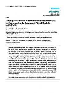
The output of the IMU discussed in this paper was compared against the data recorded in a smartphone. A graph of IMU accelerometer output with the smartphone data for a walking trial while keeping the devices in the same pants pocket is shown in Fig. 7. This comparison indicated that the output of the IMU goes close to the data of the smartphone which indicate that the performance of the IMU is satisfactory. It should be noted that no additional computations are done to the output of the IMU other than the conversion form row values to the actual units. V. D ISCUSSION AND F UTURE W ORK At the beginning of developing this IMU, the goal was set to achieve a sampling rate of 100 Hz as it is sufficient to track natural walking paces of 2 – 3 steps·s−1 for fast gait [4]. However, with the data rates supported by Bluetooth version 2.0, higher sampling rates can also be achieved. Authors are currently working on improving the sampling rate of the IMU. However, with the limitations of Bluetooth bandwidth, the number of IMUs that can be connected with a single Bluetooth receiver will be limited as sampling rate increases. Another factor that limits the sampling rate is the speed of I2 C supported by the microcontroller and the sensors. Although the microcontroller supports I2 C baud rates up to 400 kHz, some sensors do not support rates higher than 100 kHz. The authors are working on finding alternative sensors that support higher I2 C baud rates. Further, the data transfer rates supported
Vertical Acceleration (y-Axis) for a Walking Trial 10
IMU Phone
8 6
Accel-X (m/s2)
4 2 0 -2 -4 -6 -8 -10 0
Figure 5. Screenshot of the Android Application
1
2
3
4 Time(s)
5
6
7
Figure 7. Accelerometer Outputs of IMU with Smartphone Data
8
2013 International Conference on Indoor Positioning and Indoor Navigation, 28th -31st October 2013 by the SD card also imposes a bottleneck for achieving higher sampling rates. The Windows application was written to receive data from a single IMU only. However, it is possible to receive data from multiple IMUs so that they can be used to track motion of a part or the full body. The authors are also looking at improving the Windows application to accommodate multiple IMU data in a time synchronized manner. The cost of the IMU with the battery and the enclosure in single units comes below US$ 100. However, if this is implemented in mass scale, the cost will be lower. It should be noted that the IMU discussed in this paper consists of most of the sensors necessary for indoor navigation and localization as well it has USB and Bluetooth connectivity and data logging features. Separate accelerometer, gyroscope and compass sensors were used in the IMU discussed in this paper to keep the cost lower as possible. However, it gives a small error in the relative sensor readings due to the fact that they have slightly offset coordinate systems (X-axis and/or Y-axis have offsets). As a future work, the authors are looking at using a 9-axis motion sensor developed by InvenSense [12] which includes a 3-axis accelerometer, a 3-axis gyroscope and a 3-axis magnetometer in a single chip. This will minimize the error due to offset of sensor axes to a greater extent. VI. C ONCLUSIONS This paper presented the design and development of a low cost IMU that consists of most of the sensors needed for indoor localization and with Bluetooth and USB data streaming and data logging in an SD card for real time data collection for human gait analysis. The IMU gave satisfactory output that is sufficient for real time data capturing for human gait analysis. R EFERENCES [1] YEI Technology. “YEI 3-Space Sensor” [Online]. Available: Internet: http://www.yeitechnology.com/yei-3-space-sensor, [July 17, 2013]. [2] x-io Technologies. “x-IMU” [Online]. Available: Internet: http://www.x-io.co.uk/products/x-imu/, [July 17, 2013]. [3] K. Abhayasinghe and I. Murray. (2012, Nov.). “A novel approach for indoor localization using human gait analysis with gyroscopic data,” in Third International Conference on Indoor Positioning and Indoor Navigation [Online], Sydney, Australia, 2012. Available: http://www.surveying.unsw.edu.au/ipin2012/proceedings/submissions/ 22_Paper.pdf [Mar. 5, 2013]. [4] T. Oberg, A. Karsznia and K. Oberg, “Basic gait parameters: Reference data for normal subjects, 10–79 years of age,” J. Rehabil. Res. Dev., vol.30 no. 2, pp.210–223, 1993. R [5] Atmel Corporation. (2009, Oct.). “8-bit AVR Microcontroller with 4/8/16/32 K Byte In-System Programmable Flash” [Online]. Available: http://www.atmel.com/Images/doc8161.pdf [July 17, 2013]. [6] Analog Devices. (2013, Feb.) “3-Axis, ±2 g /±4 g /±8 g /±16 g Digital Accelerometer” [Online]. Available: http://www.analog.com/static/imported-files/data_sheets/ADXL345.pdf [July 17, 2013]. [7] InvenSense Inc. (2011, Feb. 08) “ITG-3200 Product Specification Revision 1.7” [Online]. Available: http://invensense.com/mems/gyro/documents/PS-ITG-3200A.pdf [July 17, 2013]. [8] Honeywell. (2013, Feb.) “3-Axis Digital Compass IC HMC5883L” [Online]. Available: http://www51.honeywell.com/aero/common/documents/ myaerospacecatalog-documents/Defense_Brochuresdocuments/HMC5883L_3-Axis_Digital_Compass_IC.pdf [July 17, 2013].
[9] Bosch Sensortec. (2009, Oct. 15) “BMP085 Digital Pressure Sensor” [Online]. Available: https://www.sparkfun.com/datasheets/Components/General/BST-BMP085-DS000-05.pdf [July 17, 2013]. [10] Texas Instruments. (2012, Oct.) “Low Power Digital Temperature Sensor with SMBusTM /Two-Wire Serial Interface in SOT563” [Online]. Available: http://www.ti.com/lit/ds/symlink/tmp102.pdf [July 17, 2013]. [11] Texas Advanced Optoelectronic Solutions. (2005, Dec.) “TSL2560, TSL2561 Light-to-Digital Converter” [Online]. Avaialble: http://www.adafruit.com/datasheets/TSL2561.pdf [July 17, 2013]. [12] Invensense. “Nine-Axis (Gyro + Accelerometer + Compass) MEMS MotionTrackingTM Devices” [Online]. Available: http://www.invensense.com/mems/gyro/nineaxis.html [July 17, 2013].