We describe a data structure for three-dimensional Nef complexes, al- gorithms
for ... Nef polyhedra were introduced by W. Nef in his seminal. 1978 book on ...
Boolean Operations on 3D Selective Nef Complexes Data Structure, Algorithms, and Implementation? Miguel Granados, Peter Hachenberger, Susan Hert, Lutz Kettner, Kurt Mehlhorn, and Michael Seel?? Max-Planck Institut f¨ur Informatik, Saarbr¨ucken
Abstract. We describe a data structure for three-dimensional Nef complexes, algorithms for boolean operations on them, and our implementation of data structure and algorithms. Nef polyhedra were introduced by W. Nef in his seminal 1978 book on polyhedra. They are the closure of half-spaces under boolean operations and can represent non-manifold situations, open and closed boundaries, and mixed dimensional complexes. Our focus lies on the generality of the data structure, the completeness of the algorithms, and the exactness and efficiency of the implementation. In particular, all degeneracies are handled.
1
Introduction
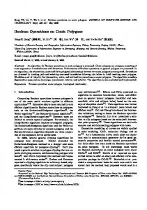
Partitions of three space into cells are a common theme of solid modeling and computational geometry. We restrict ourselves to partitions induced by planes. A set of planes partitions space into cells of various dimensions. Each cell may carry a label. We call such a partition together with the labelling of its cells a selective Nef complex (SNC). When the labels are boolean ({in, out}) the complex describes a set, a so-called Nef polyhedron [23]. Nef polyhedra can be obtained from halfspaces by boolean Fig. 1. A Nef polyhedron with operations union, intersection, and complement. non-manifold edges, a dangling Nef complexes slightly generalize Nef polyhedra facet, two isolated vertices, and through the use of a larger set of labels. Figure 1 an open boundary in the tunnel. shows a Nef polyhedron. Nef polyhedra and complexes are quite general. They can model non-manifold solids, unbounded solids, and objects comprising parts of different dimensionality. Is this generality needed? ?
??
Work on this paper has been partially supported by the IST Programme of the EU as a Shared-cost RTD (FET Open) Project under Contract No IST-2000-26473 (ECG - Effective Computational Geometry for Curves and Surfaces), and by the ESPRIT IV LTR Project No. 28155 (GALIA). We thank Sven Havemann and Peter Hoffmann for helpful discussions. Email:
[email protected], [hachenberger|hert|kettner| mehlhorn]@mpi-sb.mpg.de,
[email protected]
1. Nef polyhedra are the smallest family of solids containing the half-spaces and being closed under boolean operations. In particular, boolean operations may generate non-manifold solids, e.g., the symmetric difference of two cubes in Figure 1, and lower dimensional features. The latter can be avoided by regularized operations. 2. In a three-dimensional earth model with different layers, reservoirs, faults, etc., one can use labels to distinguish between different soil types. Furthermore, in this application we encounter complex topology, for example, non-manifold edges. 3. In machine tooling, we may want to generate a polyhedron Q by a cutting tool M. When the tool is placed at a point p in the plane, all points in p + M are removed. Observe, when the cutting tool is modeled as a closed polyhedron and moved along a path L (including its endpoints) an open polyhedron is generated. Thus open and closed polyhedra need to be modeled. The set of legal placements for M is the set / C may also contain lower dimensional features. This is C = { p; p + M ∩ Q = 0}; one of the examples where Middleditch [22] argues that we need more than regularized boolean operations. In the context of robot motion planning this example is referred to as tight passages, see [14] for the case of planar configuration spaces. SNCs can be represented by the underlying plane arrangement plus the labeling of its cells. This representation is space-inefficient if adjacent cells frequently share the same label and it is time-inefficient since navigation through the structure is difficult. We give a more compact and unique representation of SNCs, algorithms realizing the (generalized) set operations based on this representation, and an implementation. The uniqueness of the representation, going back to Nef’s work [23], is worth emphasizing; two point sets are the same if and only if they have the same representation. The current implementation supports the construction of Nef polyhedra from manifold solids, boolean operations (union, intersection, complement, difference, symmetric difference), topological operations (interior, closure, boundary), rotations by rational rotation matrices (arbitrary rotation angles are approximated up to a specified tolerance [7]). Our implementation is exact. We follow the exact computation paradigm to guarantee correctness; floating point filtering is used for efficiency. . Our representation and algorithm refine the results of Rossignac and O’Connor [24], Weiler [31], Gursoz, Choi, and Prinz [13], and Dobrindt, Mehlhorn, and Yvinec [10], and Fortune [12]; see Section 7 for a detailed comparison. Our structure explicitly describes the geometry around each vertex in a so-called sphere map; see Figure 4. The paper is structured as follows: Nef polyhedra are reviewed in Section 2, our data structure is defined in Section 3, and the algorithms for generalized set operations are described in Section 4. We discuss their complexity in Section 5. We argue that our structure can be refined so as to handle special cases (almost) as efficient as the special purpose data structures. The status of the implementation is discussed in Section 6. We relate our work to previous work in Section 7 and offer a short conclusion in Section 8.
2
Theory of Nef Polyhedra
We repeat a few definitions and facts about Nef polyhedra [23] that we need for our data structure and algorithms. The definitions here are presented for arbitrary dimensions, but we restrict ourselves in the sequel to three dimensions.
2
Definition 1 (Nef polyhedron). A Nef-polyhedron in dimension d is a point set P ⊆ Rd generated from a finite number of open halfspaces by set complement and set intersection operations. Set union, difference and symmetric difference can be reduced to intersection and complement. Set complement changes between open and closed halfspaces, thus the topological operations boundary, interior, exterior, closure and regularization are also in the modeling space of Nef polyhedra. In what follows, we refer to Nef polyhedra whenever we say polyhedra. A face of a polyhedron is defined as an equivalence class of local pyramids that are a characterization of the local space around a point. Definition 2 (Local pyramid). A point set K ⊆ Rd is called a cone with apex 0, if K = R+ K (i.e., ∀p ∈ K, ∀λ > 0 : λp ∈ K) and it is called a cone with apex x, x ∈ Rd , if K = x + R+ (K − x). A cone K is called a pyramid if K is a polyhedron. Now let P ∈ Rd be a polyhedron and x ∈ Rd . There is a neighborhood U0 (x) of x such that the pyramid Q := x + R+ ((P ∩ U(x)) − x) is the same for all neighborhoods U(x) ⊆ U0 (x). Q is called the local pyramid of P in x and denoted PyrP (x). Definition 3 (Face). Let P ∈ Rd be a polyhedron and x, y ∈ Rd be two points. We define an equivalence relation x ∼ y iff PyrP (x) = PyrP (y). The equivalence classes of ∼ are the faces of P. The dimension of a face s is the dimension of its affine hull, dim s := dim aff s. In other words, a face s of P is a maximal non-empty subset of Rd such that all of its points have the same local pyramid Q denoted PyrP (s). This definition of a face partitions Rd into faces of different dimension. A face s is either a subset of P, or disjoint from P. We use this later in our data structure and store a selection mark in each face indicating its set membership. Faces do not have to be connected. There are only two full-dimensional faces possible, one whose local pyramid is the space Rd itself and the other with the empty set as a local pyramid. All lower-dimensional faces form the boundary of the polyhedron. As usual, we call zero-dimensional faces vertices and one-dimensional faces edges. In the case of polyhedra in space we call two-dimensional faces facets and the fulldimensional faces volumes. Faces are relative open sets, e.g., an edge does not contain its end-vertices. Example 1. We illustrate the definitions with an example in the plane. Given the closed halfspaces h1 : y ≥ 0,
h2 : x − y ≥ 0,
h3 : x + y ≤ 3,
h4 : x − y ≥ 1,
h5 : x + y ≤ 2,
we define our polyhedron P := (h1 ∩ h2 ∩ h3 ) − (h4 ∩ h5 ). Figure 2 illustrates the polyhedron with its partially closed and partially open boundary, i.e., vertex v4 , v5 , v6 , and edges e4 and e5 are not part of P. The local pyramids for the faces are PyrP ( f1 ) = 0/ and PyrP ( f2 ) = R2 . Examples for the local pyramids of edges are the closed halfspace h2 for the edge e1 , PyrP (e1 ) = h2 , and the open halfspace that is the complement of h4 for
3
v2
f1 e1 e3
v6
e1
e2
e4
e3
e5
e2
e5 v5 e4 v1
f2
f1
f2
v4
v1
e3
v2
v3
v4
v5
v6
v3
Fig. 2. Planar example of a Nef-polyhedron. The shaded region, bold edges and black nodes are part of the polyhedron, thin edges and white nodes are not.
Fig. 3. Sketches of the local pyramids of the planar Nef polyhedron example. The local pyramids are indicated as shaded in the relative neighborhood in a small disc.
the edge e5 , PyrP (e5 ) = {(x, y)|x − y < 1}. The edge e3 consists actually of two disconnected parts, both with the same local pyramid PyrP (e3 ) = h1 . In our data structure, we will represent the two connected components of the edge e3 separately. Figure 3 lists all local pyramids for this example. Definition 4 (Incidence relation). A face s is incident to a face t of a polyhedron P iff s ⊂ clost. This defines a partial ordering ≺ such that s ≺ t iff s is incident to t. Bieri and Nef proposed several data structures for storing Nef polyhedra in arbitrary dimensions. In the W¨urzburg Structure [6], named after the workshop location where it was first presented, all faces are stored in the form of their local pyramids, in the Extended W¨urzburg Structure the incidences between faces are also stored, and in the Reduced W¨urzburg Structure [5] only the local pyramids of the minimal elements in the incidence relation ≺ are stored. For bounded polyhedra all minimal elements are vertices. Either W¨urzburg structure supports Boolean operations on Nef polyhedra, neither of them does so in an efficient way. The reason is that W¨urzburg structures do not store enough geometry. For example, it records the faces incident to an edge, but it does not record their cyclic ordering around the edge.
3
Data Structures
In our representation for three-dimensions, we use two main structures: Sphere Maps to represent the local pyramids of each vertex and the Selective Nef Complex Representation to organize the local pyramids into a more easily accessible polyhedron representation. It is convenient (conceptually and, in particular, in the implementation) to only deal with bounded polyhedra; the reduction is described in the next section. 3.1 Bounding Nef Polyhedra We extend infimaximal frames [29] already used for planar Nef polygons [28, 27]. The infimaximal box is a bounding volume of size [−R, +R]3 where R represents a sufficiently large value to enclose all vertices of the polyhedron. The value of R is left unspecified as an infimaximal number, i.e., a number that is finite but larger than the value of any concrete real number. In [29] it is argued that interpreting R as an infimaximal number instead of setting it to a large concrete number has several advantages, in particular increased efficiency and convenience. 4
sphere map vertex svertex sphere map svertex
edge
vertex
svertex
ge
d se
dge
ted e
orien
use
svertex sedge
oriented facet
edge use
opposite
Fig. 4. An example of a sphere map. The different colors indicate selected and unselected faces.
edge use
Fig. 5. An SNC. We show one facet with two vertices, their sphere maps, the connecting edges, and both oriented facets. Shells and volumes are omitted.
Clipping lines and rays at this infimaximal box leads to points on the box that we call frame points or non-standard points (compared to the regular standard points inside the box). The coordinates of such points are R or −R for one coordinate axis, and linear functions f (R) for the other coordinates. We use linear polynomials over R as coordinate representation for standard points as well as for non-standard points, thus unifying the two kind of points in one representation, the extended points. From there we can define extended segments with two extended points as endpoints. Extended segments arise from clipping halfspaces or planes at the infimaximal box. It is easy to compute predicates involving extended points. In fact, all predicates in our algorithms resolve to the sign evaluation of polynomial expressions in point coordinates. With the coordinates represented as polynomials in R, this leads to polynomials in R whose leading coefficient determines their signs. We will also construct new points and segments. The coordinates of such points are defined as polynomial expressions of previously constructed coordinates. Fortunately, the coordinate polynomials stay linear even in iterated constructions. Lemma 1. The coordinate representation of extended points in three-dimensional Nef polyhedra is always a polynomial in R with a degree of at most one. This also holds for iterated constructions where new planes are formed from constructed (standard) intersection points. (Proof omitted due to space limitations.) 3.2 Sphere Map The local pyramids of each vertex are represented by conceptually intersecting the local neighborhood with a small ε-sphere. This intersection forms a planar map on the sphere (Figure 4), which together with the set-selection mark for each item forms a two-dimensional Nef polyhedron embedded in the sphere. We add the set-selection mark for the vertex and call the resulting structure the sphere map of the vertex. Sphere maps were introduced in [10]. We use the prefix s to distinguish the elements of the sphere map from the threedimensional elements. An svertex corresponds to an edge intersecting the sphere. An sedge corresponds to a facet intersecting the sphere. Geometrically the edge forms a great arc that is part of the great circle in which the supporting plane of the facet intersects the sphere. When there is a single facet intersecting the sphere in a great circle, we 5
get an sloop going around the sphere without any incident vertex. There is at most one sloop per vertex because a second sloop would intersect the first. An sface corresponds to a volume. This representation extends the planar Nef polyhedron representation [27]. 3.3 Selective Nef Complex Representation Having sphere maps for all vertices of our polyhedron is a sufficient but not easily accessible representation of the polyhedron. We enrich the data structure with more explicit representations of all the faces and incidences between them. We also depart slightly from the definition of faces in a Nef polyhedron; we represent the connected components of a face individually and do not implement additional bookkeeping to recover the original faces (e.g., all edges on a common supporting line with the same local pyramid) as this is not needed in our algorithms. We discuss features in the increasing order of dimension; see also Figure 5: edges: We store two oppositely oriented edges for each edge and have a pointer from one oriented edge to its opposite edge. Such an oriented edge can be identified with an svertex in a sphere map; it remains to link one svertex with the corresponding opposite svertex in the other sphere map. edge uses: An edge can have many incident facets (non-manifold situation). We introduce two oppositely oriented edge-uses for each incident facet; one for each orientation of the facet. An edge-use points to its corresponding oriented edge and to its oriented facet. We can identify an edge-use with an oriented sedge in the sphere map, or, in the special case also with an sloop. Without mentioning it explicitly in the remainder, all references to sedge can also refer to sloop. facets: We store oriented facets as boundary cycles of oriented edge-uses. We have a distinguished outer boundary cycle and several (or maybe none) inner boundary cycles representing holes in the facet. Boundary cycles are linked in one direction. We can access the other traversal direction when we switch to the oppositely oriented facet, i.e., by using the opposite edge-use. shells: The volume boundary decomposes into different connected components, the shells. They consist of a connected set of facets, edges, and vertices incident to this volume. Facets around an edge form a radial order that is captured in the radial order of sedges around an svertex in the sphere map. Using this information, we can trace a shell from one entry element with a graph search. We offer this graph traversal in a visitor design pattern to the user. volumes: A volume is defined by a set of shells, one outer shell containing the volume and several (or maybe none) inner shells excluding voids from the volume. For each face we store a label, e.g., a set-selection mark, which indicates whether the face is part of the solid or if it is excluded. We call the resulting data structure Selective Nef Complex, SNC for short.
4
Algorithms
Here we describe the algorithms for constructing sphere maps for a polyhedron, the corresponding SNC, and the simple algorithm that follows from these data structures for performing boolean operations on polyhedra. 6
4.1 Construction of a Sphere Map We have extended the implementation of the planar Nef polyhedra in C GAL to the sphere map. We summarize the implementation of planar Nef polyhedra described in [28, 27] and explain the changes needed here. The boolean operations on the planar Nef polyhedra work in three steps—overlay, selection, and simplification—following [24]. The overlay computes the conventional planar map overlay of the two input polyhedra with a sweep-line algorithm [21, section 10.7]. In the result, each face in the overlay is a subset of a face in each input polyhedron, which we call the support of that face. The selection step computes the mark of each face in the overlay by evaluating the boolean expression on the two marks of the corresponding two supports. This can be generalized to arbitrary functions on label sets. Finally, the simplification step has to clean up the data structure and remove redundant representations. In particular, the simplification in the plane works as follows: (i) if an edge has the same mark as its two surrounding regions the edge is removed and the two regions are merged together; (ii) if an isolated vertex has the same mark as its surrounding region the vertex is removed; (iii) and if a vertex is incident to two collinear edges and all three marks are the same then the vertex is removed and the two edges are merged. The simplification is based on Nef’s theory [23, 4] that provides a straightforward classification of point neighborhoods; the simplification just eliminates those neighborhoods that cannot occur in Nef polyhedra. The merge operation of regions in step (i) uses a union find data structure [8] to efficiently update the pointers in the half-edge data structure associated with the regions. We extend the planar implementation to sphere maps in the following ways. We (conceptually) cut the sphere into two hemispheres and rotate a great arc around each hemisphere instead of a sweep line in the plane. The running time of the sphere sweep is O((n + m + s) log(n + m)) for sphere maps of size n and m respectively and an output sphere map of size s. Instead of actually representing the sphere map as geometry on the sphere, we use three-dimensional vectors for the svertices, and three-dimensional plane equations for the support of the sedges. Step (iii) in the simplification algorithm needs to be extended to recognize the special case where we can get an sloop as result. 4.2 Classification of Local Pyramids and Simplification In order to understand the three-dimensional boolean operations and to extend the simplification algorithm from planar Nef polyhedra to three-dimensions, it is useful to classify the topology of the local pyramid of a point x (the sphere map that represents the intersection of the solid with the sphere plus the mark at the center of the sphere) with respect to the dimension of a Nef face that contains x. It follows from Nef’s theory [23, 4] that: – x is part of a volume iff its local sphere map is trivial (only one sface f s with no boundary) and the mark f s corresponds to the mark of x. – x is part of a facet f iff its local sphere map consists just of an sloop l s and two incident sfaces f1s , f2s and the mark of l s is the same as the mark of x. And at least one of f1s , f2s has a different mark. – x is part of an edge e iff its local sphere map consists of two antipodal svertices vs1 , vs2 that are connected by a possible empty bundle of sedges. The svertices vs1 , vs2
7
and x have the same mark. This mark is different from at least one sedge or sface in between. – x is a vertex v iff its local sphere map is none of the above. Of course, a valid SNC will only contain sphere maps corresponding to vertices. But some of the algorithms that follow will modify the marks and potentially invalidate this condition. We extend the simplification algorithm from planar Nef polyhedra to work directly on the SNC structure. Based on the above classification and similar to the planar case, we identify redundant faces, edges, and vertices, we delete them, and we merge their neighbors. 4.3 Synthesizing the SNC from Sphere Maps Given the sphere maps for a particular polyhedron, we wish to form the corresponding SNC. Here we describe how this is done. The synthesis works in order of increasing dimension: 1. We identify svertices that we want to link together as edges. We form an encoding for each svertex consisting of: (a) a normalized line representation for the supporting line, e.g. the normalized Pl¨ucker coordinates of the line [30], (b) the vertex coordinates, (c) a +1 or −1 indicating whether the normalization of the line equation reversed its orientation compared to the orientation from the vertex to the svertex. We sort all encodings lexicographically. Consecutive pairs in the sorted sequence form an edge. 2. Edge-uses correspond to sedges. They form cycles around svertices. The cycles around two svertices linked as an edge have opposite orientations. Thus, corresponding sedges are easily matched up and we have just created all boundary cycles needed for facets. 3. We sort all boundary cycles by their normalized, oriented plane equation. We find the nesting relationship for the boundary cycles in one plane with a conventional two-dimensional sweep line algorithm. 4. Shells are found with a graph traversal. The nesting of shells is resolved with ray shooting from the lexicographically smallest vertex. Its sphere map also gives the set-selection mark for this volume by looking at the mark in the sphere map in −x direction. This concludes the assembly of volumes. 4.4 Boolean Operations We represent Nef polyhedra as SNCs. We can trivially construct an SNC for a halfspace. We can also construct it from a polyhedral surface [18] representing a closed 2-manifold by constructing sphere maps first and then synthesizing the SNC as explained in the previous section. Based on the SNC data structure, we can implement the boolean set operations. For the set complement we reverse the set-selection mark for all vertices, edges, facets, and volumes. For the binary boolean set operations we find the sphere maps of all vertices of the resulting polyhedron and synthesize the SNC from there: 1. Find possible candidate vertices. We take as candidates the original vertices of both input polyhedra, and we create all intersection points of edge-edge and edge-face intersections. Optimizations for an early reduction of the candidate set are possible. 8
2. Given a candidate vertex, we find its local sphere map in each input polyhedron. If the candidate vertex is a vertex of one of the input polyhedra, its sphere map is already known. Otherwise a new sphere map is constructed on the fly. We use point location, currently based on ray shooting, to determine where the vertex lies with respect to each polyhedron. 3. Given the two sphere maps for a candidate vertex, we combine them into a resulting sphere map with boolean set operation on the surfaces of the sphere maps. The surfaces are 2D Nef polyhedra. 4. Using the simplification process described in Section 4, we determine if the resulting sphere map will be part of the representation of the result. If so, we keep it for the final SNC synthesis step. We can also easily implement the topological operations boundary, closure, interior, exterior, and regularization. For example, for the boundary we deselect all volume marks and simplify the remaining SNC (Section 4). The uniqueness of the representation implies that the test for the empty set is trivial. As a consequence, we can imple/ and the equality ment for polyhedra P and Q the subset relation as P ⊂ Q ≡ P − Q = 0, comparison with the symmetric difference.
5
Complexity and Optimizations
Let the total complexity of a Nef polyhedron be the number of vertices, edges, and faces. Given the sphere map representation for a polyhedron of complexity n, the synthesis of the SNC is determined by sorting the Pl¨ucker coordinates, the plane sweep for the facet cycles, and the shell classification. It runs in O(n log n + c · T↑ ) where T↑ is the time needed for shooting a ray to identify the nesting relationship of one of the c different shells. This is currently the cost for constructing a polyhedron from a manifold solid. Given a polyhedron of complexity n, the complement operation runs in time linear in n. The topological operations boundary, closure, interior, exterior, and regularization require simplification and run in time O(n · α(n)) with α(n) the inverse Ackermann function from the union-find structures in the simplification algorithm. Given one polyhedron of complexity n and another polyhedron of complexity m, the boolean set operation that produces a result of complexity k has a runtime that decomposes into three parts. First, TI , the total time to find all edge-face and edgeedge intersections. We also subsume in TI the time needed to locate the vertices of one polyhedron in the respective other polyhedron. Let s be the number of intersections vertices found in this step. Second, O((n + m + s) log(n + m)) is the runtime for the overlay computation of all n + m + s sphere map pairs. Third, after simplification of the sphere maps we are left with k maps and the SNC synthesis runtime from above applies here with the time O(k log k + c · T↑ ). We have kept the runtime cost for point location and intersection separate since we argue that we can choose among different well known and efficient methods in our approach, for example, octrees [26] or binary space partition (BSP) trees [9]. The space complexity of our representation is clearly linear in our total complexity of the Nef polyhedron. However, in absolute numbers we pay for our generality in various ways. We argue to use exact arithmetic and floating point filters. However, since cascaded construction is possible, we have to store the geometry using an exact 9
arithmetic type with unbounded precision. We further added the infimaximal box for unbounded polyhedra. Its coordinate representation uses a (linear) polynomial in the infimaximal R and thus doubles the coordinates we have to store. Both, the arithmetic and the extended kernel for the infimaximal box, are flexible and exchangeable based on the design principles of C GAL. So, assuming a user can accept less general arithmetic 1 and a modeling space restricted to bounded polyhedra then we can offer already in our current implementation a choice of number type and kernel that makes the geometry part of the SNC equal to other conventional representations in size and expressiveness. What remains is the space complexity of the connectivity description (ignoring the geometry). We compare the SNC with a typical data structure used for three-dimensional manifold meshes, the polyhedral surface in C GAL based on halfedges [18]. We need five to eight times more space for the connectivity in the SNC; five if the polyhedral surface is list based and eight if it is stored more compactly—but also less powerful—in an array. Clearly this can be a prohibitive disadvantage if the polyhedron is in most places a local manifold. Although not implemented, there is an easy optimization possible that can give the same space bounds. We can specialize the sphere maps for vertices that are locally an oriented 2-manifold to just contain a list of svertices and sedges plus two volumes. Now, assuming also that the majority of vertices has a closed boundary, we can also remove the labels from the sphere map. Whenever needed, we can reconstruct the full sphere map on the fly, or even better, we can specialize the most likely operations to work more efficiently on these specialized sphere maps to gain performance.
6
Implementation
The sphere maps and the SNC data structure with the extended kernel for the infimaximal box are fully implemented in C GAL2 [11] with all algorithms described above. We also support the standard C GAL kernels but restricted to bounded polyhedra. The above description breaks the algorithms down to the level of point location (for location of the candidate vertices in the input polyhedra), ray shooting (for assembling volumes in the synthesis step), and intersection finding among the geometric primitives. The current implementation uses inefficient but simple and complete implementations for these substeps. It supports the construction of Nef polyhedra from manifold solids [18], boolean operations (union, intersection, complement, difference, symmetric difference), topological operations (interior, closure, boundary, regularization), rotations by rational rotation matrices (arbitrary rotation angles are approximated up to a specified tolerance [7]). Our implementation is exact. We follow the exact computation paradigm to guarantee correctness; floating point filtering is used for efficiency. The implementation of the sphere map data structure and its algorithms has about 9000 lines of code, and the implementation of the SNC structure with its algorithms and the visualization graphics code in OpenGL has about 15000 lines of code. Clearly, the implementation re-uses parts of C GAL; in particular the geometry, the floating point filters, and some data structures. 1 2
For example, bounded depth of construction or interval arithmetic that may report that the accuracy is not sufficient for a certain operation.
10
A bound on the necessary arithmetic precision of the geometric predicates and constructions is of interest in geometric algorithms. Of course, Nef-polyhedra can be used in cascaded constructions that lead to unbounded coordinate growth. However, we can summarize here that the algebraic degree is less than ten in the vertex coordinates for all predicates and constructions. The computations of the highest degree are in the plane sweep algorithm on the local sphere map with predicates expressed in terms of the three-dimensional geometry. We support the construction of a Nef polyhedron from a manifold solid defined on vertices. Nef polyhedra are also naturally defined on plane equations and combined with C GAL’s flexibility one can realize schemes where coordinate growth is handled favorably with planes as defining geometry [12].
7
Comparison to Extant Work
Data structures for solids and algorithms for boolean operations on geometric models are among the fundamental problems in solid modeling, computer aided design, and computational geometry [16, 20, 25, 15, 12]. In their seminal work, Nef and, later, Bieri and Nef [23, 6] developed the theory of Nef polyhedra. Dobrindt, Mehlhorn, and Yvinec [10] consider Nef polyhedra in three-space and give an O((n + m + s) log(n + m)) algorithm for intersecting a general Nef polyhedron with a convex one; here n and m are the sizes of the input polyhedra and s is the size of the output. The idea of the sphere map is introduced in their paper (under the name local graph). They do not discuss implementation details. Seel [27, 28] gives a detailed study of planar Nef polyhedra; his implementation is available in C GAL. Other approaches to non-manifold geometric modeling are due to Rossignac and O’Connor [24], Weiler [31], Karasick [17], Gursoz, Choi, and Prinz [13], and Fortune [12]. Rossignac and O’Connor describe modeling by so-called selective geometric complexes. The underlying geometry is based on algebraic varieties. The corresponding point sets are stored in selective cellular complexes. Each cell is described by its underlying extent and a subset of cells of the complex that build its boundary. The non-manifold situations that occur are modeled via the incidence links between cells of different dimension. The incidence structure of the cellular complex is stored in a hierarchical but otherwise unordered way. No implementation details are given. Weiler’s radial-edge data structure [31] and Karasick’s star-edge boundary representation are centered around the non-manifold situation at edges. Both present ideas about how to incorporate the topological knowledge of non-manifold situations at vertices; their solutions are, however, not complete. Cursoz, Choi and Prinz [13] extend the ideas of Weiler and Karasick and center the design of their non-manifold modeling structure around vertices. They introduce a cellular complex that subdivides space and that models the topological neighborhood of vertices. The topology is described by a spatial subdivision of an arbitrarily small neighborhood of the vertex. Their approach gives thereby a complete description of the topological neighborhood of a vertex. Fortune’s approach centers around plane equations and uses symbolic perturbation of the planes’ distances to the origin to eliminate non-manifold situations and lowerdimensional faces. Here, a 2-manifold representation is sufficient. The perturbed polyhedron still contains the degeneracies, now in the form of zero-volume solids, zero-
11
length edges, etc. Depending on the application, special post-processing of the polyhedron might be necessary, for example, to avoid meshing a zero-volume solid. Postprocessing was not discussed in the paper and it is not clear how expensive it would be. The direction of perturbation, i.e., towards or away from the origin, can be used to model open and closed boundaries of facets. We improve the structure of Gursoz et al. with respect to storage requirements and provide a more concrete description with respect to the work of Dobrindt et al. as well as a first implementation. Our structure provides maximal topological information and is centered around the local view of vertices of Nef polyhedra. We detect and handle all degenerate situations explicitly, which is a must given the generality of our modeling space. The clever structure of our algorithms helps to avoid the combinatorial explosion of special case handling. We use exact arithmetic to achieve correctness and robustness, combined with floating point filters based on interval arithmetic, to achieve speed. That we can quite naturally handle all degeneracies, including non-manifold structures, as well as unbounded objects and produce always the correct mathematical result differentiates us from other approaches. Previous approaches using exact arithmetic [1– 3, 12, 19] work in a less general modeling space, some unable to handle non-manifold objects and none able to handle unbounded objects.
8
Conclusion and Future Directions
We achieved our goal of a complete, exact, and correct implementation of boolean operations on a very general class of polyhedra in space. The next step towards practicability is the implementation of faster algorithms for point location, ray shooting, intersection finding, and the specialized compact representation of sphere maps for manifold vertices. Useful extensions with applications in exact motion planning are Minkowski sums and the subdivision of the solid into simpler shapes, e.g., a trapezoidal or convex decomposition in space. For ease of exposition, we restricted the discussion to boolean flags. Larger label sets can be treated analogously. Nef complexes are defined by planes. We plan to extend the data structure and algorithms to complexes defined by curved surfaces [24, 15].
References 1. A. Agrawal and A. G. Requicha. A paradigm for the robust design of algorithms for geometric modeling. Computer Graphics Forum, 13(3):33–44, 1994. 2. R. Banerjee and J. Rossignac. Topologically exact evaluation of polyhedra defined in CSG with loose primitives. Computer Graphics Forum, 15(4):205–217, 1996. 3. M. Benouamer, D. Michelucci, and B. Peroche. Error-free boundary evaluation based on a lazy rational arithmetic: a detailed implementation. Computer-Aided Design, 26(6), 1994. 4. H. Bieri. Nef polyhedra: A brief introduct. Comp. Suppl. Springer Verlag, 10:43–60, 1995. 5. H. Bieri. Two basic operations for Nef polyhedra. In CSG 96: Set-theoretic Solid Modelling: Techniques and Applications, pages 337–356. Information Geometers, April 1996. 6. H. Bieri and W. Nef. Elementary set operations with d-dimensional polyhedra. In Comput. Geom. and its Appl., LNCS 333, pages 97–112. Springer Verlag, 1988.
12
7. J. Canny, B. R. Donald, and E. K. Ressler. A rational rotation method for robust geometric algorithms. In Proc. ACM Sympos. Comput. Geom., pages 251–260, 1992. 8. T. H. Cormen, C. E. Leiserson, and R. L. Rivest. Introd. to Algorithms. MIT Press, 1990. 9. M. de Berg, M. van Kreveld, M. Overmars, and O. Schwarzkopf. Computational Geometry: Algorithms and Applications. Springer Verlag, 1997. 10. K. Dobrindt, K. Mehlhorn, and M. Yvinec. A complete and efficient algorithm for the intersection of a general and a convex polyhedron. In Proc. 3rd Workshop Alg. Data Struct., LNCS 709, pages 314–324, 1993. 11. A. Fabri, G.-J. Giezeman, L. Kettner, S. Schirra, and S. Sch¨onherr. On the design of CGAL a computational geometry algorithms library. Softw. – Pract. Exp., 30(11):1167–1202, 2000. 12. S.J. Fortune. Polyhedral modelling with multiprecision integer arithmetic. Computer-Aided Design, 29:123–133, 1997. 13. E. L. Gursoz, Y. Choi, and F. B. Prinz. Vertex-based representation of non-manifold boundaries. Geometric Modeling for Product Engineering, 23(1):107–130, 1990. 14. D. Halperin. Robust geometric computing in motion. Int. J. of Robotics Research, 21(3):219– 232, 2002. 15. M. Hemmer, E. Sch¨omer, and N. Wolpert. Computing a 3-dimensional cell in an arrangement of quadrics: Exactly and actually! In ACM Symp. on Comp. Geom., pages 264–273, 2001. 16. C. M. Hoffmann. Geometric and Solid Modeling – An Introd. Morgan Kaufmann, 1989. 17. M. Karasick. On the Representation and Manipulation of Rigid Solids. Ph.D. thesis, Dept. Comput. Sci., McGill Univ., Montreal, PQ, 1989. 18. L. Kettner. Using generic programming for designing a data structure for polyhedral surfaces. Comput. Geom. Theory Appl., 13:65–90, 1999. 19. J. Keyser, S. Krishnan, and D. Manocha. Efficient and accurate B-rep generation of low degree sculptured solids using exact arithmetic. In Proc. ACM Solid Modeling, 1997. 20. M. M¨antyl¨a. An Introd. to Solid Modeling. Comp. Science Press, Rockville, Maryland, 1988. 21. K. Mehlhorn and S. N¨aher. LEDA: A Platform for Combinatorial and Geometric Computing. Cambridge University Press, 1999. 22. A. E. Middleditch. ”The bug” and beyond: A history of point-set regularization. In CSG 94 Set-theoretic Solid Modelling: Techn. and Appl., pages 1–16. Inform. Geom. Ltd., 1994. 23. W. Nef. Beitr¨age zur Theorie der Polyeder. Herbert Lang, Bern, 1978. 24. J. R. Rossignac and M. A. O’Connor. SGC: A dimension-independent model for pointsets with internal structures and incomplete boundaries. In M. Wozny, J. Turner, and K. Preiss, editors, Geometric Modeling for Product Engineering. North-Holland, 1989. 25. J. R. Rossignac and A. G. Requicha. Solid modeling. http://citeseer.nj.nec. com/209266.html. 26. H. Samet. The Design and Analysis of Spatial Data Structures. Addison-Wesley, 1990. 27. M. Seel. Implementation of planar Nef polyhedra. Research Report MPI-I-2001-1-003, MPI f¨ur Informatik, Saarbr¨ucken, Germany, August 2001. 28. M. Seel. Planar Nef Polyhedra and Generic Higher-dimensional Geometry. PhD thesis, Universit¨at des Saarlandes, Saarbr¨ucken, Germany, 5. December 2001. 29. M. Seel and K. Mehlhorn. Infimaximal frames: A technique for making lines look like segments. to appear in Comp. Geom. Theory and Appl., www.mpi-sb.mpg.de/˜ mehlhorn/ftp/InfiFrames.ps, 2000. 30. J. Stolfi. Oriented Projective Geometry: A Framework for Geometric Computations. Academic Press, New York, NY, 1991. 31. K. Weiler. The radial edge structure: A topological representation for non-manifold geometric boundary modeling. In M. J. Wozny, H. W. McLaughlin, and J. L. Encarnac¸ao, editors, Geom. Model. for CAD Appl., pages 3–36. IFIP, May 12–16 1988.
13