Boolean operations on feature-based models Yvon Gardan
Christian Minich
Estelle Perrin
CMCAO Team / IFTS Pôle de Haute Technologie 08000 Charleville-Mézières France, Charleville-Mézières, Ardennes
CMCAO Team / Metz university Île du Saulcy 57045 METZ Cedex 01 France, Metz, Moselle
CMCAO Team / Metz university Île du Saulcy 57045 METZ Cedex 01 France, Metz, Moselle
[email protected]
[email protected]
[email protected] ABSTRACT
Boolean operations and feature-based modeling are closely linked domains. For example, several, sometimes many Boolean operations are involved during a feature instantiation or modification. So Boolean combinations are tools used “inside” feature-based modeling and it is interesting to study the way to make these operations faster or less numerous by using the fact that they are applying to features. This is the first issue this paper deals with. Symmetrically, Boolean operators may be used to combine two feature-based objects. This occurs, for example, when a genetic algorithm is used to semi-automatically generate the shape of a product from requirements. The second part of the paper tackles the Boolean operation optimization in this specific context. This includes improving Boolean operations performances and incrementally maintaining the feature-based model of the object resulting from a Boolean operation.
Keywords Boolean operations, feature-based modeling, geometric and topological representations, geometric interrogations and reasoning, computational geometry, robustness of geometric computations.
1. INTRODUCTION For a long time, CAD/CAM systems have been only based on geometrical models (such as boundary representation (B-Rep) and Constructive Solid Geometry (CSG)). These models made it possible to develop a number of important treatments such as objects combination, visualization, analysis and manufacturing. Some of these algorithms, for example the Boolean combination of two objects through a union, intersection or difference, are complex and time consuming. Today, new trends try hard to take higher semantic notions into account, such as the product specifications, requirements or functions [Gar00a][Gar99]. The intent is to use this new information to better carry out the tasks quoted above. In this context, Boolean operations still play a Permission to make digital or hard copies of all or part of this work for personal or classroom use is granted without fee provided that copies are not made or distributed for profit or commercial advantage and that copies bear this notice and the full citation on the first page. To copy otherwise, or republish, to post on servers or to redistribute to lists, requires prior specific permission and/or a fee. Journal of WSCG, Vol.11, No.1., ISSN 1213-6972 WSCG’2003, February 3-7, 2003, Plzen, Czech Republic Copyright UNION Agency – Science Press.
predominant role because they can be used in genetic algorithms to semi-automatically generate a product from specifications. In this context, a form feature is considered to be a geometrical solution for one or several requirements of specifications. Classical problems of genetic algorithms are solution coding, solutions crossover and mutations. A solution can be coded by a feature based object. The crossover mechanism consists in randomly choosing a Boolean operation applied to the two parent solutions, form feature type and values for feature parameters. Finally, to mutate a solution, one just has to randomly change one or more feature parameters. For such algorithms, Boolean operations have to be fast and/or less numerous. Instead of dealing just with geometrical information, a first step in this direction is to make the most of features, which are a kind of semantic information. In this paper, we deal with the relationships between feature-based modeling and Boolean operations in two different ways. The latter operations are first seen as internal tools for feature-based modeling. For example, several, sometimes many Boolean operations are involved during a feature instantiation or modification. So the first part of the paper studies the way to lower the number of topological combinations depending on what kind of treatment they are
involved: feature instantiation or feature modification. Symmetrically, Boolean operators can be used to combine two feature-based objects and then, they have a more external role. The second part of the paper tackles the Boolean operation optimization in this specific context and, again, two issues are investigated in detail: (1) how to compute the boundary representation of the resulting object by taking the most of the feature-based models of both operands; (2) how to deduce the feature-based model of the resulting object from the feature-based models of both operands. The later work is still in progress: we prove an interesting result which allows to concentrate on the union operator and present the approaches which seem the most promising to us.
2. PREVIOUS WORK Boolean operations Needs of CAD/CAM systems obliged Boolean operations algorithm to take into account a wide variety of objects: polyhedral objects, non-manifold objects and objects with non-planar faces. Methods belong to two families: those that directly use B-Reps [Mar87a][Mar87b][Man83][Pil89][Ma88] and those that use an intermediate representation (like octree representation [Nav86][Pla93]). They all rely on the following sequence of statements: calculate the intersections, combine, classify and extract entities (faces, edges and vertices) of the operands. Intersections computations concern entities of various types (edge-face intersection, face-face intersection…) and the process that classifies entities differs for each method (section polygon that splits objects in inner or outer sets, classification of subfaces (interior or exterior) by using point classification). As a result, the main drawbacks of these methods are: (1) imprecise computations; these methods have to deal with tolerances in order to compare two floats or to calculate intersections; (2) a significant computation time that may end up with a wrong result; (3) a lot of particular cases; (4) a difficult adaptation to other kinds of objects (non planar or non-manifold faces). The method developed in our team, called the “sections method” [Gar96a], solves the major drawbacks mentioned above because it formalizes the 3D Boolean operations in using 2D Boolean operations as described by the following equation: O1 ⊗ 3 D O 2
= ∪ ∪
[F(O1 ) ⊗ 2D I(O 2 )] [F(O 2 ) ⊗ 2D I(O1 )] [F(O1 ) ⊗ 2D F(O 2 )]
where ⊗ may
represent union, intersection or difference. The first and the second terms both represent a Boolean operation between the faces of an object and the interior of the other, which can be expressed as several two dimensional Boolean operations. Each
2D Boolean operation involves a face of an object and the section of the other by the face’s surface. The word “section” denotes the interior of the set of all points common to an object and a plane or a surface. The 2D Boolean operations depend on the 3D one. The last term represents the particular case of same surface faces. Its result depends on the interior’s position in the neighborhood of the faces to be combined. The ∪ operator denotes that faces must be joined to form the resulting object. This treatment is realized in considering topological information to limit errors due to computations.
REGAIN Feature-based modeler Feature-based modeling is an extremely rich topic [Ros90][Che95a][Che95b][Bid98][Bid00], but this paper focuses on relationships between feature management and Boolean operations. The featurebased modeler we used is REGAIN [Gar96b], which has been developed in our team like the Boolean operations algorithm mentioned above. In this paper, our goal is not to compare REGAIN with other feature-based modelers but to give a short overview of the system architecture and highlight the important aspects for the rest of this paper. In REGAIN, a part has both a geometric and a feature-based description. The former is a boundary polyhedral representation. The latter is roughly an ordered list of the features the user inserted in the part. A feature is a parameterized object such as a cylinder, box, fin, pocket or any other shape which takes on a given semantics in a given business. We distinguish library features, the so-called generic features, from their instances, which we call instanced features. Generic features are gathered in a hierarchy, in order to factorize elements common to several features (data or behavior). The top level of the hierarchy is an abstract class (“features”) and immediately below, the difference between primary and secondary features appears: the former give its outline to the design object (cylinder, box...), the latter are shape modifications which generally have a local influence (rib, mounting bracket, fillet...). Any generic feature is made up of a generative surface, parameters, a conceptual graph and various other constraints such as equations or inequations. In what follows, only the generative surface is useful. The generative surface limits a half space which allows to compute the amount of matter the feature adds or removes. For a primary feature, the generative surface is simply its boundary (e.g. six faces, twelve edges … for a box). For a secondary feature, the surface is generally open and extends infinitely in the directions where the instanced feature shall have to extend to reach the limits of the part that will carry it (Figure 1.a shows the
generative surfaces of a L-slot and a square tenon). This gives the feature a behavior of automatic adjustment to the part which carries it (Figure 1.d). An instanced feature refers to a generic feature and complements it by preserving the value of its parameter, the coordinate system transformation to apply to locate it in the right place on the solid which carries it, constraints and the matter volume that it has added to or removed from it, called useful volume in the following. One aspect this paper emphasizes is the link between Boolean operations and features instantiation. So the steps involved during instantiation have to be detailed. An instantiation begins with the acquisition of the parameters’ values, the feature’s dimensioning, its positioning and its orientation. These stages are not detailed here. For a primary feature, instantiation is finished; useful volume is the feature itself. On the other hand, a secondary feature must still be combined with its carrier, depending on a process we will summarize in what follows. The preliminary instantiation phases yields the feature generative surface and correctly dimensions, positions and orientates it. To assess the feature’s useful volume, a Boolean operation is first carried out between the half space limited by the generative surface on the one hand, and the carrier on the other hand; it is an intersection for matter removal (V1 and V2 in Figure 1.b) and a difference for matter addition (V3 and V4 in Figure 1.b). Among the computed volumes, called candidates, those which are not finite (for example V4) or which do not have at least one face on each face of the generative surface (for example V2, since none of its faces coincides with the “bottom” of the L-slot generative surface) are deleted. All together, the remaining volumes (V1 for the slot, V3 for the tenon) make up the useful volume and are preserved in the instanced feature. Another Boolean operation ends the instantiation by combining the carrier with the useful volume, through a difference for matter removal and a union for an addition (so V1 were subtracted and V3 were added to the part in Figure 1.d). Computing the useful volume of each instanced feature also allows to maintain a tree which models the part’s shape as shown on Figure 2. At the very beginning, the tree is only made up of the useful volume of the first (primary) feature used to build the part. Then, every feature instantiation generates a Boolean node, the left son of which is the current tree and the right son of which is the useful volume of the new feature. The Boolean node is a union or a difference, depending on whether the feature is positive or negative. All right nodes in this particular tree are restricted to a single node, so the tree looks like a comb. In what follows, the comb associated to
a feature-based object will denote the tree built with this procedure. Figure 2 shows an object created with a box, a L-slot, a tenon and a blind slot and the associated comb. V2
V3
a b V1 V4
d c
Figure 1: (a) two generative surfaces, (b) candidate volumes for both features, (c) useful and closing faces for V1, (d) after instantiation of both features
3. BOOLEAN OPERATIONS DURING FEATURE INSTANTIATION As explained above, the instantiation of a secondary feature involves two Boolean operations. This makes the feature instantiation costly. The first Boolean operation calculates the useful volume and the second one the resulting object. Each Boolean operation processes the two operands face by face as explained in section 2. The first Boolean operation works on faces of the carrier volume and faces of the generative surface and builds the useful volume. The second one works on faces of the carrier volume and faces of the useful volume, that is faces of the carrier volume and the generative surface. So finally faces of the resulting object are parts of the carrier volume faces and of the generative surface faces. As both Boolean operations work on the same faces, we had the idea to check whether it was possible to merge the two operations into one.
∪ -
a
b
Figure 2: a feature-based object (a) and the corresponding comb (b) We have demonstrated [Gar00b] that the two Boolean operations can be reduced to one treatment in using the same formalism as the one applied for the “sections method”. We have proved that whatever the Boolean operations applied (so whatever the nature of the feature), each part of a face that both belongs to the feature and to the useful volume, belongs to the resulting object. Similarly, each part of a face that belongs to the carrier volume and that does not belong to the useful volume belongs to the resulting object. In conclusion, this means that adding a new feature can be realized by only one special Boolean operation instead of two.
4. COMBINING TWO FEATUREBASED OBJECTS This section is dedicated to another classical relationship between Boolean operations and featurebased modeling. We are trying to highlight what can be made faster or with more reliability during the combination of two objects which are both featurebased and, thus, to which a comb was associated (see 2). In the next section, we use the fact that features useful volumes are known, that they can be used to check inclusions and save the combination algorithm from many computations in order to get the resulting boundary representation. And we explore the different possibilities to build the feature based object of the resulting object.
Getting the boundary representation of the resulting object The main processing in the combination of two BReps is to calculate the parts of an operand face that belong to the resulting object. By extending this idea to feature-based object, we get: the main processing in the combination of two feature-based objects is to calculate the parts of a feature operand that belong to the resulting object. Suh and Ahluwalia make a similar reasoning in [Suh91][Suh99] but with a different intent. Their goal is to predict which features occur in the resulting object if a featurebased object (FBO) is combined with a primitive solid (PS), like a cube, a box, a cylinder, a sphere,
etc. To achieve this, they detect the interactions between PS and FBO by breaking down PS's boundary into parts exterior or interior to the featurebase object. This classification helps them in detecting which feature the combination has deleted, kept as they are or modified. But to determine the classification, Boolean operations are necessary so this approach is not compatible with our aim which is precisely to reduce the complexity of a single Boolean operation. Our idea is to use a pre-processing in order to detect what features can be neglected during the Boolean operation. Such features are those which are totally unchanged or totally deleted. This raises a major problem: how to detect whether a feature can be neglected (we call this treatment feature-feature filter)? The features of an operand that can be neglected are those which are totally exterior or interior to the other operand: depending on the Boolean operation, they can only be deleted or unchanged. For example, the union of two objects is formed by parts of both operands which are exterior to the other operand. So exterior features are unchanged and interior features are deleted. Our feature-feature filter can be summed up as follows: For each form feature FF of O If FF is interior to O’ Then Switch Boolean operation Case union: neglect FF Case intersection: keep FF as it is Case difference: If (O = O1) Then neglect FF Else Keep reversed FF End Switch ElseIf FF is exterior to O’ Then Switch Boolean operation Case union: keep FF Case intersection: neglect FF Case difference: If (O = O1) Then keep FF Else neglect FF End Switch Else process FF
The main difficulty of this algorithm is to assign a status to each feature, that is to find out whether it is interior, exterior or if it has an interference with the other operand. This is solved by using the useful volumes of all features and the fact that they add or remove material. Let us call FF the feature under study, FFUV its useful volume, FF1, FF2, ... , FFn the features of the other object in a chronological order and FFUVi their useful volumes. To initialize the status of FF, its useful volume FFUV is compared with FFUV1 and four results are possible: FF is included in FF1, FF1 is included in FF, FF has no interference with FF1, and FF has an interference
with FF1. Then, FF's status is set as follows: if FF1 is included in FF or if FF has no interference with FF1 then FF's status is exterior; if FF is included in FF1 then status is interior; else status is interference.
B2 A4
If the current if FFi adds if FFi subtracts material material status is … Interior
Interior
Exterior
Exterior
Interior
Exterior
Interference
Interior
Exterior
Table 1. FF is included in FFi
B1
A2
A3
A1
A2 B3
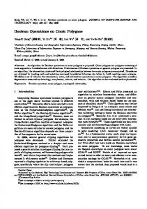
Figure 3: A 2D example: object A has four features named A1 to A4, object B has three features named B1 to B3. State1 State2 State3 State4
If the current if FFi adds if FFi subtracts material material status is …
A1
Interfere s
Interfere s
Interfere s
Interior
Interior
Interior
A2
Interior
Interior
Exterior
Exterior
Exterior
Exterior
A3
Interior
Interior
Interference
Interference
Interference
Interfere s
A4
Interior
Interior
Interior
B1
Interfere s
Interfere s
Interfere s
Interfere s
B2
Exterior
Exterior
Exterior
Exterior
B3
Interfere s
Interfere s
Interfere s
Interfere s
Table 2. FF has no intersection with FFi If the current if FFi adds if FFi subtracts status is … material material Interior
Interference
Interference
Exterior
Interference
Interference
Interference
Interference
Interference
Table3. FF interferes with FFi If the current if FFi adds if FFi subtracts material material status is … Interior
Interior
Interior
Exterior
Exterior
Exterior
Interference
Interference
Interference
Table 4. FF contains FFi Generally, FF1 is a primary form feature like a box or a cylinder, so it adds material. If this shouldn't be the case, the status should be reversed (interior and exterior should be switched). FFVU is then compared with all the other useful volumes. The status evolves as the traversal makes progress. Tables 1,2 3,4 give the next status, knowing its current value, the result of the useful volumes comparison and the nature of FFi (it adds or subtracts material). Ê A1
A2
A3
A4
B1
Interferes
Includes
Includes
Includes
B2
No intersection
No intersection
No intersection
No intersection
B3
Interferes
Includes
Intersects
No intersection
Table 5. Results after the first step for the example of figure 3. Let us trace this algorithm on an example (see Figure 3). The first step studies each form feature with regard to the others (see table 5).
Table 6. State evolution for features of A and B. Table 6 means that A1, A3, B1 and B3 must be considered during the combination of A and B, whatever the Boolean operation is. The other features (A2, A4 and B2) are unchanged or deleted: this depends on the requested Boolean operation but they can all be neglected during computations.
Building the FBM of the resulting object We demonstrated in the previous section how to make the most of the design histories of both operands of a Boolean operation to perform this operation faster. However, the Boolean operation only provides the geometric model of the resulting object, not its feature-based representation. This means that the resulting object can not be combined with any other object using the optimized Boolean operators. This is the reason why we are trying to exhibit a feature-based model of the object resulting from a Boolean combination. For that purpose, a general extraction algorithm could be applied to the resulting object. But there is no reason that the algorithm provides with features that are mostly the same as the ones the designer used to create the two operands: there are many feature-based models of the same part. As the features the designer inserted in the operands are part of his design intent, we consider that those which still appear in the resulting object should also appear in its feature-based model. This is why, instead of using a general feature extraction algorithm, we are trying to maintain the feature-based model in an
incremental way, by re-using as much as possible the feature-based models of the operands. The next section gives the proof that the complementary of a comb is the comb of the complementary features. The next two sections deliver our first thoughts on the way to build an incremental extraction algorithm on the basis of this result.
4.1.1 Getting the difference and the intersection combs from the union comb Intersection and difference can be expressed by union and complementary as follows: A∩B=A∪B (equation 1) and A−B=A∪B (equation 2). We have to calculate the design history (called comb in this section) of an object that results from a Boolean operation between two feature-based objects. We suppose that we are able to calculate the comb of an object that comes from a union of two feature-based objects. In this section, we prove that the design history of the complementary of an object can be easily deduced from the design history of this object. For that, the complementary of a feature has to be defined:
Definition 1: The complementary of a feature F is a feature F’ which adds (respectively subtracts) matter when F subtracts (respectively adds) matter. The useful volume obtained by applying F on an object O is the same as the one obtained by applying F’ on the complementary of O (this means that F and F’ may have the same parameters). By example, the complementary of a pocket is a tenon (see Figure 4).
a)
Interior
b)
Useful volume
Figure 4: a) a box with a pocket b) a complementary of a box with a tenon. The complementary of the complementary of a box with a tenon is the box with a pocket. A tenon and a pocket are complementary features. Let us now prove that the complementary of a comb is the comb of the complementary features. First, let us suppose that we have a comb named C and the last feature added to C is a positive feature named F whose useful volume is VU. As F is
positive, the last Boolean operation in the tree is a union between the sub-comb SC and VU. Let us now calculate the complementary of C.
C =SC ∪VU = SC ∪VU =SC −VU =SC −VU according to equation2. This result means that there exists a negative feature F’ whose useful volume is VU (so the same as F’s one) which subtracts matter to the complementary of SC. A similar proof can be done if the last feature added to C is negative. In that case, the starting hypothesis is a difference between the sub-comb and the useful volume of the feature:
C =SC −VU =SC ∪VU = SC ∪VU according
to
equation2. This result means that there exists a feature F’ whose useful volume is VU (so the same as F’s one) which adds matter to the complementary of C. By recursion, these two cases can be applied to SC in order to obtain the complementary of C. In conclusion, as the union operation and the complementary can express the intersection and the difference operations, we can suppose that it is sufficient to only consider the union operation in the next sections.
4.1.2 Geometric and topological reasoning It was proved in the previous section that extracting features in the difference or the intersection of two objects could be performed through extraction in the union of two objects. Thus, in what follows, we focus on feature extraction in the object produced by the union of two solids. To perform this extraction, one option consists in writing a particular extraction algorithm, which makes the most of the fact that the object to be processed was built by uniting to feature-based objects. This section briefly presents the two potential approaches we plan to study, for this adapted extraction algorithm. Both approaches are consequences of the following observation: before the extraction algorithm is run, the boundary representations of both operands are combined by the optimized algorithm described in “Getting the boundary representation of the resulting object”. As the considered operation is a union, if none of the faces of a feature in an operand is modified, this feature also belongs to the resulting object. So all its faces can be neglected by the dedicated extraction algorithm; it just has to focus on all remaining faces. Of course, it is enough that one feature face is modified to make it necessary to put all its faces in the list of faces to be processed. In what follows, this face list is called FL.
First approach: Each face in FL is a useful face or part of a useful face. This means that many geometric constraints and equation link them. For example, if the side face of a slot was removed, the other side and the bottom belong to FL and an orthogonal constraint links them. Then it can be checked what generic features have constraint sets and face sets compatible with these hints. In this example, a step might be a good example. Of course, it might happen that it is necessary to combine faces from various previous features to get a set that can fit a generic feature. So the extraction algorithm will consist in grouping together all faces in FL in all possible manners. This provides many combinations, each one being made up of several face sets. For each combination, it is checked whether each face set in the combination can be matched with a generic feature (see [Gup95] for a similar approach). A first version of an extraction algorithm working on this principle is operational. This algorithm has the following properties: it is exhaustive, because it produces all interpretations of a solid as a combination of features of the library; it is extensible to any type of user-defined feature; it provides semantically rich information, as each feature is delivered with its rank, parameters, orientation, nature, useful volume and accessibilities. As the underlying principle leads to a combinatorial explosion, we plan to use several heuristics to increase the probability to reach a solution earlier: 1) To meet the design intent, it seems reasonable to first look for occurrences of features which existed in one of the operands. For example, if only parts of a feature face were removed, the feature might still exist in the resulting object. So the combination which lets together the faces of a previous feature are generated. 2) The combinations where adjacent faces are grouped together are generated first. The probability that some faces make up a feature is larger if they are adjacent than if they are far one another. 3) If it was not possible to interpret a combination of features, the face sets that could not be paired with a feature are re-arranged first, those which could be matched with a feature are kept as long as all combinations of remaining faces are not tried. 4) It often happens that a feature, when it loses one of its faces, derives into another feature. Classic examples are the slot which becomes a step, the pocket which becomes an open pocket, a blind slot or a slot… The fact of knowing several possible evolutions of usual features and the conditions to get one evolution or another (such as loosing a side face), might make things easier: as all face
modifications are provided by the BRep combination algorithm, it becomes possible to predict with better probabilities what each modified feature becomes. Moreover, during a union, there is only added matter. This means that features in both operands which are not completely removed can only be added pieces of matter: in particular, a negative feature can only decrease, that is it can only be partly filled. So derivation rules for negative features should focus on evolutions caused by matter addition. So the slot which becomes a blind slot and the open pocket which becomes a pocket are better examples than the rules listed on top of this paragraph. Second approach: Another approach would be to keep all positive features (i.e. all positive features whose at least one face belongs to the resulting object) and to reduce the negative features. We remind that this approach is valid because we only have to consider the union operation. In a union, positive features can not create too much matter in the resulting object. Concerning the negative features, we know if they still belong (even partially) to the resulting object. If they are partially covered, matter of the second operand has trimmed them. This means that negative features would subtract too much matter if they were kept as they are. It is then possible to think to an algorithm that would limit the useful volume of negative features. If part of a face of a negative feature exists in the resulting object, then we can deduce that the negative feature still exists in the resulting object with a reevaluation of its parameters. The new values of parameters can be calculated by using topological information given by the “sections method”: faces that cut the remaining faces of negative features are known. Then by propagation, concavities could be localized and the useful volumes of negative features truncated. Nevertheless, the order of appearance in the comb has to be checked. But this step is not easy and may not converge. That is the reason why, in the next section, we keep the same idea (the base is a union of positive features) but we extract new negative features from the concavities in the resulting object. Instead of designing a new extraction tool, one could also use an existing algorithm but only within a limited area. One way to get this area is to build an object with all positive features of both operands which are not entirely included in the other operand. This produces an object O, which is a superset of the part U resulting from the union. Subtracting U from O yields a volume corresponding to all extra matter to which any machining feature extraction algorithm can be applied. The feature-based model of U is then the concatenation of all positive features in both
operands and of all negative features recognized in O. This method seems to be convenient when both operands are mostly made up of positive features, as merging all positive features gives a good outline of the final part. If operands were designed with a destructive paradigm, the best would probably be to apply techniques sketched out in the previous section.
5. CONCLUSION AND FUTURE WORKS This paper has investigated some of the numerous links between Boolean operations and feature-based modeling. It has underlined the possibility to reduce in a significant way the number of Boolean operations performed during a feature instantiation or modification. It has also presented how the complexity of a Boolean operation combining two feature-based objects could be appreciably reduced. Finally, we focused on getting the feature-based model of the resulting object under the assumption that the Boolean combination of the boundary representations supplies the faces which are not changed, those which disappear and those which are modified. Only the union and complement operations have been considered as we proved that, provided that each feature has a complement, the feature-based representation of an object resulting from the intersection or difference of two feature-based objects object is the same as the one of an object made up of a union and complements. Two possible research directions have been proposed to deal with the problem of building a feature-based model for the object resulting from the union of two feature-based objects. Whatever the approach we will implement, Boolean operations appear to be a support of feature extraction in boundary representations.
6. References [Bid98] R. Bidarra, K. J. de Kraker, W.F. Bronsvoort, “Representation and management of feature information in a cellular model”, Computer aided design, volume 30, n°4, pp 301-313, 1998 [Bid00] R. Bidarra, W.F. Bronsvoort, “Semantic feature modeling”, Computer Aided Design, Vol 32, pp 201-225, 2000 [Che95a] X.Chen, C.M. Hoffmann, “Towards feature attachment”, Computer aided design, volume 27, n°11, pp 675-702, 1995 [Che95b] X.Chen, C.M. Hoffmann, “On editability of feature-based design”, Computer aided design, 27(12):905-914, 1995 [Gar96a] Y. Gardan, E. Perrin, “An algorithm reducing 3D boolean operations to a 2D problem : concepts and results”, Computer aided design, volume 28, n°4, pp 277-287, 1996
[Gar96b] Y. Gardan, C. Minich, C. Poinsignon, “Proposals for a product model ”, IDMME '96, Integrated Design and Manufacturing, Nantes, France, April 15-17, 1996 [Gar99] Y. Gardan, C. Minich, D. Pallez, “On shape to specifications adequacy”, IV99, July 14-16, Londres, England, 1999 [Gar00a] Y. Gardan, C. Minich, D. Pallez, E. Perrin, “Towards a specifications-to-shape translation tool , TMCE 2000, pp 373-382, April 18-21, Delft, The Netherlands, 2000 [Gar00b]Y. Gardan, E. Perrin, “Boolean operations and feature-based objects”, CISST'2000, pp 563-569, June 26-29, Monte Carlo Resort, Las Vegas, Nevada, USA, 2000 [Gup95] S.K. Gupta, D.S. Nau, “Systematic approach to analyzing the manufacturability of machined parts”, Computer Aided Design, 27(5):323-342, 1995 [Ma88] D. Ma, R. Tang, “Realizing the boolean operations in solid modeling technique via directed loops”, Computer and Graphics, volume 12, n° ¾, 1988 [Man83] M. Mantyla, M. Tamminen, “Localized set operations for solid modeling”, Computer and Graphics, volume 17, n°3, 1983 [Mar87a] D. Martin, P. Martin, “Les algorithmes de calcul de l'intersection de solides définis par leur bord”, Revue internationale de CFAO et d'infographie, volume 2, n°4, 1987 [Mar87b] D. Martin, P. Martin, “Les algorithmes de calcul de l'intersection de solides définis par leur bord”, Revue internationale de CFAO et d'infographie, volume 3, n°2, 1987 [Nav86] I. Navazo, D. Ayala, P. Brunet, “A geometric modeler based on the exact octtree representation of polyhedra”, Computer Graphics Forum, volume 5, 1986 [Pil89] M. Pilz, H.A. Kamel, “Creation and boundary evaluation of CSG models”, Engineering with Computers, volume 5, pp 105-118, 1989 [Pla93] N. Pla-Garcia, “Boolean operations and spatial complexity of face octrees”, Eurographics’93, volume 12, n°3, 1993 [Ros90] J.R. Rossignac, “Issues on feature-based editing and interrogation of solid models”, Computer and Graphics, 14(2):149-172, 1990 [Suh91] H. Suh, R. S. Ahluwalia, J. E. Miller, “Feature generation in concurrent engineering environment”, Proceedings of the first symposium on solid modeling foundations and CAD/CAM applications, pp 495-502, November 5-7, Austin, Texas, 1991 [Suh99] H. Suh, R. S. Ahluwalia, “Feature modification in incremental feature generation”, Computer aided design, volume 27, n°8, pp 627-635, 1999