BUILDING COMPLEX AUTOMATION SYSTEMS BASED ON THE SIMULATION OF OBJECT-ORIENTED BASIC COMPONENTS W. Fleisch, P. Göhner, R. Belschner, M. Gunzert Institute for Automation and Software Engineering (IAS) University of Stuttgart Pfaffenwaldring 47 D-70569 Stuttgart, Germany e-mail:
[email protected] ABSTRACT Over the last 10 years, the focus of development in automation engineering has changed fundamentally. In the past hardware development was the main task. Nowadays software development is becoming more and more important. At present the success in complex automation projects depends mainly on the faultless operation of the software. Without new methods in the development process it is probable that developers will not be able to handle the increasing software complexity in the future. A complex software project consists of many different components, which are either purchased from commercial manufacturers or are individually developed for a certain project. System integration of the different components usually causes a lot of problems related to interface consistency and timing. In particular distributed real-time systems in the automation field must meet the imposed specifications concerning their temporal behavior. Our approach is that developers of large and complex software systems in the automation field should build a new application just by reusing validated or proven object-oriented components and assure the software is functioning by simulation before the system has been built. For this purpose, the conception of a simulation system is presented providing features for developing components as well as composing and simulating complex systems. This paper is based on a simulation system [Belschner94] for distributed real-time systems which has been developed at the IAS over the last three years and the experience gained in the predecessor project. The authors intend to present the ideas to a competent audience to start a fertile discussion and collect useful feedback and suggestions. The final goal of this project is to handle the increasing complexity of software in automation projects and to improve the software quality and reliability as well as the life cycle costs.
INTRODUCTION In common with other fields, developers of automation systems are fighting with increasing complexity. Alongside the hardware development it is usual to build up systems with standard components purchased from commercial manufacturers. Although the importance of faultless software in automation systems is well known, most software applications are still implemented by individual programming and many faults are integrated into a system in that way.
For efficient development of applications in industrial automation many manufacturers offer tools for building control software using standard function-libraries covering functions like process monitoring, supervisor control, alert reaction, realtime charts, static process control and communication-services for distributed automation systems. In addition resource workshops for building GUIs (Graphical User Interface) from standard class-libraries are already available. Using such proven standard components is a first step for improving software quality in industrial automation. The disadvantage is that it is only offered for simple I/O-controls and general automation tasks connected with PLCs (Programmable Logical Control). Useful simulation and analysis tools which allow analysis of the dynamic behaviour of complex and distributed automation systems in an early phase of the development-cycle are still missing in this field. For larger automation systems in particular, the efficiency of simulation-based analysis and optimization of heterogeneous automation systems including technical process, communication networks, real-time operating systems and interpretable control software specifications has been demonstrated in research work at the IAS [Belschner95a] over recent years. In the area of control systems, first commercial tools provide good test and development environments for real-time applications but the software development process for these applications is not really affected. Software development is still carried out manually by trial and error. Object-oriented modelling methods like ROOM (Real-time Object-Oriented Modelling) [Krasovec95] in the area of real-time software development will improve software quality and reusability but they just support programming with graphical processing instead of using proven components for composing complex software systems. Some car manufacturers are now using tools for modelling, simulating and analyzing like CANoe [CANoe96], from VectorInformatik GmbH, Germany, for distributed CAN-Bus applications in automotive electronics or ASCET [ASCET95], from ETAS GmbH, Germany, for development of linear and non-linear motor control systems for high performance real-time simulation combined with hardware-in-the-loop testing. Developers of time-critical software for real-time operating systems like VxWorks, QNX etc. can use software development environments for example TORNADO [TORN95], from WindRiver Systems corporation, which offers POSIX 1003.1b real-time UNIX extensions and analysis opportunities like process schedule monitoring and other analysis features as well as source code generation for different target platforms. These tools support development of very special application fields but they are not made for development of heterogeneous systems like distributed automation systems. Using such tools is
commercially viable when high numbers of units are produced and application developers have to reduce hardware costs like memory and processing performance to a minimum. One way of fighting complexity is to support developers with tools for simulation and analysis but another way to reach the goal is the general improvement of development methods which means composing distributed software systems from problem adapted components instead of programming.
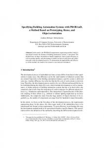
ASSURING SOFTWARE CORRECTNESS THROUGH SIMULATION When building a new complex and distributed software system in the automation field we need the assurance of software functionality before the system has been implemented. Beside the application of software engineering concepts, the simulation of run time aspects, like time predictability, is of importance. Simulation performance tests can be conducted and, if the performance is not acceptable, software restructuring, scheduling policy or load balancing can be applied. Different simulations with variable system parameters illustrate the behaviour of the entire system and reveal bottle-necks as well as deadlocks. The evidence of assuring software correctness through simulation is supported by the procedure of simulation based analysis which is shown in Fig. 1. The architecture of the simulation based analysis system consists of three layers [Belschner95b]. The simulation layer consists of an interpretable software specification, which is individually composed for an automation problem and the simulation model, which is composed of standard components like technical process environment, communication networks and operating systems running on different processor nodes. The analysis layer automatically evaluates specified timing requirements from time stamps which are captured from the software specifications and the simulation model during a simulation run. The optimization layer optimizes selected system parameters from the simulation layer with the help of different optimization strategies.
Optimization Layer
Analysis Layer
Software Specification
Simulation Model
Simulation Layer Fig. 1: Overview of a simulation based analysis system
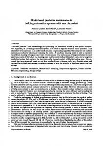
AN EXAMPLE FOR A LARGE DISTRIBUTED AUTOMATION SYSTEM To obtain an impression of a distributed automation system Fig. 2 presents a system consisting of two real-time QNX processor nodes connected via CAN-bus with the distributed technical process of a modular production system.
QNX
QNX
Controller Area Network (CAN)
CAN I/O
CAN I/O
...
CAN I/O
Modular Production System (Festo) (29 Sensors, 20 Actuators) Fig. 2: Example of a distributed automation system
SPECIFICATION OF THE DISTRIBUTED REAL-TIME SOFTWARE SYSTEM The specification of the distributed real-time software system determines and influences the behaviour of the automation system. So it is absolutely necessary to specify the essential parts of a real-time software system as precisely as possible in an early phase of the development-cycle. Standard software specification languages like Estelle, LOTOS and SDL [Fleischmann94] have been analyzed to determine whether they meet the imposed requirements for software specifications in distributed automation systems. Estelle is based on extended finite state machines which are defined as modules. The modules can be built hierarchically and interact via asynchronous communication channels. Estelle offers basic constructs for the description of state transitions. Temporal behaviour can be modelled by delay-instructions which delay the execution of a transition. The Formal Description Technique of LOTOS is based on the specification of processes which can be decomposed into actions. Essential characterization of LOTOS is that the system behaviour is described on an abstract level without knowledge of a systems internal state. A process may change its behaviour when executing temporal conditioned events. Finally the events determine the temporal behaviour of the specified system. Additionally data typing and arithmetic operations are supported. The main emphasis of SDL is the specification of parallel processes and the communication between those processes. SDL supports data typing and system structuring, but not hierarchy. The specification languages introduced here are on a very abstract level and have been developed especially for telecommunication problems. Missing elements for the description of the program flow and real-time language constructs from the POSIX 1003.4 specification have influenced the decision to develop the specification language EPOSIX which supports not only the qualities of the standard specification languages mentioned above but even particular the specification of POSIX 1003.4 RT-UNIX features like interprocess communication, process primitive functions, timer functions etc.. An introduction to the language elements of EPOSIX can be found in [Belschner95a].
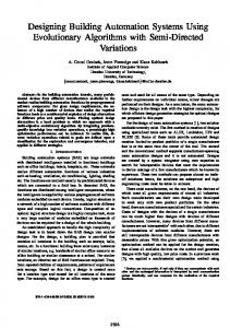
Simulation Model
Network Model
Operating System Model
Environment Model
CAN Driver Model
Scheduler Model
State Models
CAN Board Model
Interrupt-Model
Petri Net Models
CAN Net Model
Processor Model
Decision Tables
IPC Model Fig. 3: Overview of the different simulation components in a distributed automation system
HIERARCHICAL MODELLING OF THE SIMULATION SYSTEM The different components of a distributed automation system can be classified into the categories • software • hardware • communication networks and • technical process environment Except for the automation software, which is specified separated by a specification language, a simulation model is created for imaging the automation system. Hierarchical modelling of a complex and distributed automation system based on vertical decomposition is a necessary mechanism to manage models’ complexity [Booch94]. The simulation system, as shown in Fig. 3., is refined and split into simulation components which can be modelled independently from each other. A simulation component can be a part of the technical process environment, the operating systems on different processor nodes, the software for system processes running on the processor nodes or the communication networks like CAN, Ethernet and other networks ordinary used for communication in distributed automation systems. Further decomposition of the automation system is natural. The CANnetwork model component, for example, is refined into the driver model, the board model and the network model which all represent independent basic simulation components. Component modelling can be made in different ways. In the simulation tool which has been developed at the IAS, the realtime operating system model and the model of the communication networks are implemented as C++-programs and are statically linked to the simulation control. Components are parametrizeable and can be loaded with different essential system parameters, like transfer rate, queue length, scheduling policy etc. Beside the technical process, the environment can be modelled flexibly in a graphical modelling tool with the help of extended state machines, petri nets and decision tables. In order to execute EPOSIX software specifications on different processor nodes an interpreter component has been developed which interacts with the operating system model.
CONCEPT OF A PROCESS-ORIENTED COMPONENT-BASED SIMULATION SYSTEM Modelling the Behaviour of a Component in a Process-Oriented View Our approach is to build an object-oriented simulation system with the help of process-oriented simulation components. The smallest units which are administrated by the simulation control are basic components like a CAN-driver, CAN-board etc.. The reason for building process-oriented simulation components is to be found in the original behaviour of the different components in the real world. In the process-oriented view, components have active phases which can be seen as processes. In real distributed automation systems many actions are running in parallel. But in a nonparallel simulation system all those actions have to be executed in sequence scheduled by the simulation control. In a similar manner to the administration of processes by a scheduler in an operating system, the simulation control is steering the simulation components in a process-oriented way. The simulation control is not directly affected by the eventoriented actions which are executed inside a component. Compared with the operating system the instructions inside a process are executed like event-oriented actions inside a component. The operating system is not even directly affected by the instructions inside a process. However this processoriented behaviour of simulation components is used for the simulation control of the simulation system. Usually a component starts its active phase when a message is received from another connected component or when a timer interrupt occurs inside. These initial events have to be checked by the simulation control and the execution control has to be distributed to the simulation components. Components suspend themselves either after they have finished all scheduled internal actions or after they have sent a message to a neighbour component which has to react to the received message. The CAN-board for example needs a defined time to store a CAN-
message which is passed from the CAN-net in its receive buffer. The execution time for this receiving process depends on the chosen transfer rate of the CAN-bus which is tuned by parameters of the simulation component. After that the simulation component returns control to the simulation control.
Process 1
Fig. 4: Process structure in a PLC Real-time software structures are naturally based on processorientation. It is not important whether it is just a single process running cyclic on a PLC (Programmable Logical Control) as presented in Fig. 4 or whether there are parallel processes running on a processor node with an operating system as shown in Fig. 5. Interrupt Handler
Appl. Process 1
Scheduler
Appl. Process 2
between one component and another independent of the implementation method of the components. A simulation model implemented in the interpretable Java language for example should be addressed through a Java-Browser. In the case that the inefficient method of distributed simulation is used, remote process communication mechanisms will be provided for example from an object request broker belonging to the Object Management Group’s CORBA-architecture [OMG91]. This various interfaces are very useful because all types of components in automation systems like hardware, software, technical process and communication network are usually purchased from many different manufacturers who know the detailed specifications of their products better than somebody else and may protect their know-how about their components in that way even when producing the simulation components for a simulation system. On the other hand automation system developers can analyze, restructure and optimize a planned complex automation system just by simulating the system before any hardware is bought or the real automation system is built up. The architecture of the simulation system interface is remeniscent of the Object Management Group’s CORBAarchitecture but it is not explicitly defined for distributed simulation systems. Maybe this will be subject of future research work about distributed simulation systems.
Appl. Process 3
System Process 4
Fig. 5: Process structure of different processes running on a processor node with an operating system It is probable that both kinds of real-time software structures can be specified in a process-oriented manner. In the example of Fig. 5 the scheduler and interrupt handler of the operating system have also to be modelled in a process-oriented manner.
Similar to the component interfaces through a CORBA object request broker or through a Java-Browser, the additional indirection produces large overhead in the simulation system which is very inefficient. Therefore it is more effective to connect simulation models through static or dynamic link mechanisms than through interpreters (browser) or remote procedure call (RPC) mechanisms.
Building Basic Simulation Components
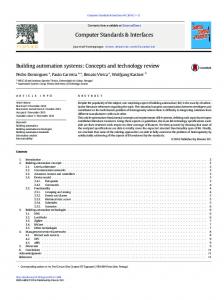
The Simulation System Parameter Simulation System Simulation Control
Reset
Component Interface DLLInterface
Static Link Interface
Browser Interface
DLL Model
Objectcode Model
JAVA Model
E5
E3
LCalendar
In-Port [1..n]
Execute
Object Request Broker
Distributed CORBAModel
E1
? Model
Suspend Return
Fig. 6: Interfaces between components and simulation control Fig. 6 shows the concept for a new component-based processoriented simulation system. The assumption is that the behaviour of each component is modelled in a process-oriented manner. Components are connected through the component interface to the simulation control. The component interface offers various adapters to simulation models implemented in different environments. The reason for this is to allow an open architecture where just a few interface specifications have to be considered by the developer of a simulation model. The component interface must enable communication between each component and the simulation control as well as data exchange
LObjectStack
Out-Port [1..n]
TSimComponent Fig. 7: Communication interfaces and control mechanisms of a basic simulation component Fig. 7 shows the essential objects of a basic simulation component. All actions inside are scheduled and executed in event-oriented manner controlled by a local calendar [Mattern89]. The functions ‘Execute’, ‘Suspend’ and ‘Return’ are the process-oriented control mechanisms from and to the simulation control. The state of a simulation component can be initialized by the ‘Reset’ function. The local object stack
guarantees persistency of the component so that the actual state of a component can be stored at any simulation time. The inand out-port objects connect one component with another and enable message based intercomponent communication. One opportunity is that all basic components inherit this basic attributes from an abstract class which defines all methods for the interfaces between simulation control and components as well as the interfaces between the port objects of two components [Kocher94]. This is just one suggestion how to build basic simulation components for the planned simulation system. Minimum condition is that simulation components just fulfil the demanded interface specifications and possesses the essential objects shown in Fig. 7. This view emphasizes encapsulated object-oriented simulation components with process-oriented behaviour. Additionally logical related components like the CAN-driver, the CAN-board and the CAN-network as shown in Fig. 3 can be combined to one network component which even exhibits process-oriented behaviour. In this way hierarchical modelling is encouraged to manage complexity by information hiding.
CONCLUSIONS & CURRENT WORK A conception for an object-oriented open simulation system based on process-oriented simulation components has been introduced. The architecture supports handling complexity with encapsulated basic simulation components and hierarchical modelling of the automation system. The purpose of the simulation system is to assure software correctness and the validation of the dynamic behaviour of complex and distributed automation systems in an early phase of the development-cycle. The implementation of the simulation system in the context of a CASE-tool will be part of the future research work. The authors intend to gain knowledge about the expected improvements of the presented component-based process-oriented simulation system.
REFERENCES [ASCET95] Advanced Simulation and Control Engineering Tool, Product Description, ETAS GmbH, Markgröninger Straße 45, D-71701 Schwieberdingen, 1995. [Belschner95a] Belschner, R.: Simulation Based Analysis on the Example of a Distributed Real-Time System and a Robot Control by Using the ECS Evolutionary Strategy. Proc. European Simulation MultiConference, Prague, Czechoslovakia, June. 1995, 709-713. [Belschner95b] Belschner, R., Lehmann, M.: Conception and Analysis of an ATM Based Communication Transfer Protocol for Distributed Real-Time Systems. IFAC Workshop, Distributed Computer Control Systems, Toulouse-Blagnac, September 1995, 97-102. [Belschner94] Belschner, R.: A Simulation System for Distributed Real-Time Systems. Proc. European Simulation Symposium, Istanbul, Turkey, 1994, 205-209. [Booch94] Booch, G.: Object Oriented Analysis and Design with Applications. Benjamin Cummings, Redwood City, CA, 1994. [CANoe96] CAN open environment, Overview and Project Description, Vector-Informatik GmbH, Friolzheimer Straße 6, D-70499 Stuttgart, 1996. [Fleischmann94] Fleischmann, A.: Distributed Systems Software Design & Implementation. Springer, Berlin, Germany, 1994, 106-200. [Krasovec95] Krasovec, Baker, Gheoghe: Target Tracking: A Real-Time Object Oriented Design Experiment, Proc. First IEEE International Conference of Complex Computer Systems, Ft. Lauderdale, November 1995, 290-297. [Kocher94] Kocher, H.: Design and Implementation of a Simulation Library Using an Object-Oriented Approach, Institute of Communications Switching and Data Technics, German language, University of Stuttgart, 1994. [Mattern89] Mattern, F., Sturm, P.: An Automatic Distributed Calendar and Appointment System, Sonderforschungsbereich 124 ‘VLSI Entwurfsmethoden und Parallelität’, Report No. SFB 124-24/89, University of Kaiserslautern, Germany, 1989. [OMG91] The Common Object Request Broker: Architecture and Specification, OMG Document Number 91.12.1, 1991 [TORN95] TORNADO for UNIX, Product Description, Wind River Systems, 1010 Atlantic Avenue, Alameda, CA 94501 USA, 1995.