Abstract. Enriching Building Automation Systems (BAS) with .... This mechanism should allow the distribution of system ...... ogy Handbook, volume 1, chapter 34.
Security in Networked Building Automation Systems Wolfgang Granzer, Wolfgang Kastner, Georg Neugschwandtner and Fritz Praus Vienna University of Technology, Inst. of Computer Aided Automation, Automation Systems Group Treitlstraße 1-3, A-1040 Vienna, Austria {wgranzer, k, gn, fpraus}@auto.tuwien.ac.at Abstract Enriching Building Automation Systems (BAS) with new services formerly provided by separate subsystems promises synergies, but increases demands on the BAS architecture. In particular, the integration of security subsystems significantly tightens security requirements on the protocol of a networked control system. First, this paper gives a survey on security in BAS. Possible threats and attacks are discussed. Weaknesses in the security mechanisms of important open networked BAS (LonWorks, BACnet, KNX/EIB) are summarized. Then, a security extension to KNX/EIB is presented. It includes several security mechanisms that guarantee data integrity, confidentiality and freshness, as well as authentication to provide secure process data and management communication. Relevant configuration related issues such as key management and distribution are also addressed.
1. Introduction Building Automation Systems (BAS) aim at improving control, monitoring and administration of technical building subsystems and interaction among devices typically found in buildings. The core BAS application area is environmental control with the traditional service types lighting/daylighting and Heating, Ventilation and Air conditioning (HVAC) systems. However, a tighter integration of formerly dedicated stand-alone systems is desirable. Extending BAS towards further application areas allows improvements in building control and cost reductions. Furthermore management and configuration of an integrated BAS becomes easier, since a variety of different management solutions can be replaced by a single tool. Obviously, the demands on a more sophisticated BAS controlling different subsystems increase. This is especially true for the integration of access control and security alarm systems. They depend on the underlying control system to be reliable and robust against malicious manipulations to fulfill their purpose. For the core BAS application areas, comparable demands have not been made up to now. Nevertheless, protection is desirable for these service types as well. As
an example, consider the adverse economic impact of a company-wide attack on the lighting system. It may easily be comparable to the effect of an attack on the company web server. With further standardization and increasing use of BAS (possibly with remote connection) adversaries can be expected to target unprotected building control systems. Thus, it seems reasonable to set up schemes for BAS providing protection as powerful as those already established in the IT (Information Technology) domain. In a networked BAS, the control network protocol has a key role in providing the required protection. Thus, this paper presents an adequate extension to the European Installation Bus (KNX/EIB). It allows the integration of subsystems with special demands on the security of the control network, thus broadening the application area. Still, it maintains downward compatibility. This allows the smooth transition of core BAS applications into a secure environment. Section 2 gives an overview of the BAS hierarchy and possible security threats. Section 3 introduces the demands on security critical applications and Section 4 discusses security mechanisms and flaws in common BAS. The remaining sections present the system architecture, design and implementation of our approach.
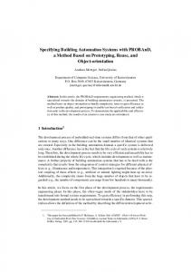
2. Security threats in BAS Communication networks in BAS are typically implemented following a two-tiered hierarchical model (cf. Fig. 1 and [1, 2]). The control level consists of intelligent sensors and actuators interacting with the environment and performing control tasks. They are interconnected by a robust, low-bandwidth and cost effective control network. The backbone level connects multiple control subnetworks. It also provides interconnections with possible foreign networks (e.g., the Internet). Management nodes requiring a global view of the entire BAS are also located at the backbone. This may include logging and backup servers to collect and archive statistical data. The backbone network features high bandwidth. For reasons of economy and compatibility, IT technology is often used (e.g., Internet Protocol networks). Depending on the data to be sent, two different types of communication exist. Exchanging process data such as sensor values is referred to as process data commu-
Management node
Backbone level
Attacking the backbone network (threat from the outside)
WAN
Backbone network
Control level
Attacking a gateway (threat from the outside) Attacking the control network (threat from the inside)
Attacking a field device (threat from the inside)
Control networks
Figure 1. Two level model and security threats in BAS
nication, whereas data transmitted for configuration and maintenance purposes are called management communication. For the protection of BAS, various measures have to be developed. It is essential to protect the system against attacks at the backbone level as well as at the control level (also shown in Fig. 1). Attackers from a public network (threat from the outside) must not gain unauthorized access to the system. Likewise, the inner network has to be protected against local attacks (threat from the inside). In both cases two attack scenarios exist. First, an individual can try to manipulate (intercept, modify, fabricate or interrupt) the traffic on the control or backbone network (attacking the network). To protect the backbone network traffic, established schemes from the IT world can be applied. However, these approved and common security mechanisms cannot be trivially mapped to the control level [3] due to resource limitations (e.g., network bandwidth, node processing power and memory). Second, an individual can directly attack an interconnection device (e.g., gateway) or field device using its network or local communication interface (attacking the device). A network interface provides access to a shared medium whereas a local interface is used for direct pointto-point communication. To avoid unauthorized access, it is essential to protect these interfaces against malicious use. In addition, measures to prevent and detect unauthorized physical access to a device have to be implemented. The latter is outside the scope of this paper, however.
3. Security demands on a BAS Creating a secure environment involves specifying a policy containing the particular security demands. To fulfill the requirements, various security mechanisms must be implemented. The following paragraphs describe the demands on a secure BAS network. To begin with, it is necessary to protect the exchanged process data (secure process data communication) as well as prevent unauthorized use of the management services (secure management communication).
Two essential elements provide the basis for both types of secure communication. On the one hand, an authentication mechanism is necessary, verifying the claimed identities of the communication partners. The identities of all involved participants have to be checked. For example, when transmitting a key update it is as important that it originates from an authorized sender as it is that it actually reaches all intended receivers. Especially, these identities must be managed in a secure manner to prevent malicious individuals from stealing or faking them. On the other hand, a secure transmission channel is necessary to protect the transmission of data between authenticated participants against malicious interference. The main objectives of such a secure transmission channel are: • Data Confidentiality: The disclosure of confidential information must be avoided. It must be guaranteed that only entities with the required privileges have access to confidential data (e.g., confidential process data, secret keys). • Data Integrity: The modification of data by unauthorized entities must be prohibited. If such a modification cannot be avoided, it must be detectable by the involved communication participants. Thus, at least the use of these corrupted data can be prevented. • Data Freshness: It must be guaranteed that the data processed by an entity is valid at the current point in time. Message injection or replaying by an unauthorized entity must be prevented. This secure channel can be provided by cryptographic algorithms, making use of secret keys. To prevent unintended disclosure of these keys, sophisticated key management is necessary. The key management facility must provide the opportunity to generate and distribute the necessary keys in a secure manner. In addition, it must also be possible to revoke old, compromised and insecure keys. To provide additional security, the lifetime of keys shall be limited and controlled using this revocation mechanism. The key management mechanism also has to be able to handle point-to-multipoint communication, as such relationships are often used in BAS. BAS need to run stable for many decades. Such systems obviously have to undergo maintenance during their lifetime in order to keep them operable. With the complexity of the embedded software increasing, it must be assumed that not all implementation flaws can be detected in the development phase. Since these may result in security vulnerabilities, an update mechanism is beneficial. This mechanism should allow the distribution of system software patches in an easy and secure manner. It can also be used to add required functionality not anticipated during development. Since BAS can consist of hundreds or even thousands of devices, appropriate scalability of the mechanisms mentioned above is essential. For instance, key distribution schemes which routinely require physical access to the individual devices are not feasible in large networks.
Therefore, services must be provided which assist in performing these tasks. Finally, the integration of a security extension into an established BAS is preferable to creating an entirely new system. Such an approach allows to leverage the existing base of available components for parts of the system where security is not (yet) a requirement. This allows a smooth transition until devices supporting the security extension become widely available. It also offers an economical upgrade path for existing installations. Downward compatibility will influence the acceptance of a security extension significantly. Such a compatible extension shall not make existing standard system components obsolete. It shall be possible to use them simultaneously with new secure devices, without mutual interference. However, security must not be compromised.
4. Security in open standard BAS In this section we analyze the security aspects of the three popular BAS: LonWorks/LonTalk [4, 5], BACNet [6, 7], and KNX/EIB [8, 9]. 4.1. LonWorks/LonTalk LonTalk provides authentication using a four step challenge-response mechanism. A sender which desires to authenticate a transmission asserts the authentication bit of its message. Receivers reply with a 64 bit random number. The sender returns a 64 bit hash value calculated over the content of the message and the random number using a shared key. The receiver performs the same calculation and compares the results. In addition to verifying the identity of the sender, data integrity as well as data freshness are provided. However, [10] describes the following security flaws: • Disclosure of confidential data cannot be avoided, since the data is transmitted in cleartext. • The authentication services only support the verification of the sender’s identity. The identity of the receiver cannot be checked. • The usage of the authentication protocol is restricted to acknowledged unicast and multicast. If broadcast or an unacknowledged transmission mode are used, the identity of the sender cannot be verified. • It is not possible to establish communication sessions. Thus, it is always necessary to transmit four messages for authentication, even if a sender transmits multiple data messages to the same receiver. • Using authenticated multicast, each receiver generates its own random number and sends it to the sender. To prove its identity, the sender must respond to all receivers with the corresponding hash value. If a multicast group contains n members, the sender must calculate n − 1 hash values. • The authentication protocol is vulnerable to Denial of Service (DoS) attacks. To start a flooding attack [11], the attacker sends a lot of messages with the
authentication bit set. For each message, the receiver will generate a random number and calculate the necessary hash value. This is time-consuming. • The cryptographic algorithm is not openly available. The key length is limited to 48 bits. Therefore, it must be assumed as being weak. • The LonTalk protocol does not provide a mechanism to distribute the secret keys in a secure manner. Hence, key distribution has to be performed in a secure environment to prevent interception. • Each node can only use one authentication key. This means that all entities that want to communicate with each other must share the same authentication key. 4.2. BACnet BACnet offers several services which provide support for data confidentiality, data integrity and data freshness as well as an authentication service [6, 10]. These mechanisms use the symmetric Data Encryption Standard (DES) algorithm and a trusted key server, which is responsible for generating and distributing session keys. These session keys are used to encrypt the transmitted data between two network nodes. To establish a secure connection to the key server, each node must own a secret key. BACnet suffers the following general security flaws [10, 12, 13]: • The generation and distribution of the initial secret keys is not defined in the BACnet standard. These mechanisms are considered “local matters”. • The freshness of the session keys cannot be guaranteed. During session establishment, the device adds the retrieved session key to the list of valid session keys. The BACnet specification does not mandatorily limit the lifetime of these session keys. Hence, an attacker can use an old session key to communicate with a particular device. • The implementation of the key server is not defined by the BACnet standard. Since the key server holds a copy of all secret keys, it is obvious that the key server must be protected against all kinds of malicious attacks. • DES is the only supported encryption algorithm. Since DES uses short keys (56 bit), brute force attacks can be performed to find valid keys [14]. In addition, [12] and [13] describe the following security flaws of the authentication service: man-in-the-middle attacks, type flaws, parallel interleaving attacks, replay attacks, and implementation dependent flaws. 4.3. KNX/EIB KNX/EIB does not offer mechanisms to guarantee data confidentiality, data integrity or data freshness. Neither does it support a dedicated authentication service. It only provides a basic access control scheme based on cleartext passwords [15]. Up to 255 different access levels can be defined, each of them associated with a different (otherwise unspecified) set of privileges. For each of these access levels, a 4 byte password (key) can be specified. This
scheme is only available for management communication. Process data exchange remains insecure1 . Since this access protection is very rudimentary, KNX/EIB does not provide the necessary mechanisms to guarantee a secure environment. Furthermore, it suffers the following general security flaws [15]: • The keys are transmitted in cleartext. • KNX/EIB does not support mechanisms to manage, generate and distribute keys in a secure manner. Therefore, the keys must be uploaded to the device manually. It is up to the system administrator to guarantee that this upload is performed in a secure environment. • To configure and maintain a KNX/EIB network, a single management tool called ETS is used. As shown in [15], it does not make full use of the access protection mechanism (e.g., only one key for the whole installation). • The access protection mechanism cannot be applied to process data communication. An unauthorized use of these services cannot be avoided. In addition to the above mentioned problems, the protocol itself is vulnerable to different security attacks [15]: • Parallel connections are not supported: if a node has established a connection with a particular device, all other connection requests are ignored. An attacker can use this restriction to perform a DoS attack. • Injection of messages: as the source address of a transmitted message can be spoofed very easily, an attacker can simply inject malicious messages. 4.4. Summary The security mechanisms of LonWorks and KNX/EIB are not sufficient to fulfill the requirements on BAS integrating security subsystems. They cannot provide an effective protection against the security threats mentioned. The security architecture of BACnet is more advanced. However, the cryptographic algorithm used is obsolete and should be replaced by a modern one (e.g., Advanced Encryption Standard (AES)). Additionally, the protocol itself must be improved to avoid certain security flaws. A key problem which has not been solved by any of these three systems is the generation and distribution of the required initial secrets. Even if the architecture of the system itself is secure, a mechanism must be available to distribute the initial secrets in a secure manner. Table 1 gives an overview of the security architectures presented. As shown, further development is necessary to provide a secure environment.
5. EIBsec: Overview Regarding the limited usability of KNX/EIB in security critical applications, we decided to develop a KNX/EIB 1 In KNX/EIB process data can only be exchanged using a pointto-multipoint communication service (called group communication) whereas management communication is point-to-point.
Authentication Integrity Confidentiality Freshness
LonWorks
BACnet
KNX/EIB
64 bit MAC (48 bit key) 64 bit MAC (48 bit key) – Random number (64 bit)
DES
32 bit password –
DES DES Random number (64 bit)
– –
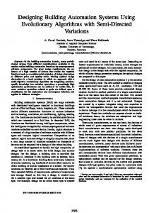
Table 1. Security mechanisms in BAS security extension called EIBsec. The main reason for selecting KNX/EIB is that it is widely used in Europe. Another motive is that KNX/EIB has only very limited security features. An extension is thus badly required. Moreover, it has the advantage to start from scratch. 5.1. Previous work At the TU Munich, a secure communication protocol called Secure EIB (SEIB) was developed [16]. This security extension provides data confidentiality, integrity and freshness for process data communication. It is based on the SNEP protocol which is part of the Secure Protocol for Sensor Networks, SPINS [17]. SEIB uses AES to encrypt the content of group messages and a 32 bit CRC (cyclic redundancy check) checksum to detect unauthorized modifications. To protect the communication against replay attacks, a 128 bit counter is used. However, a number of problems still remain unsolved: • Management communication is not protected. • The used key management is very rudimentary. • Key revocation is not supported. • The lifetime of keys cannot be limited. • Mechanisms to perform software updates are not available. • Due to only rudimentary key management, the protocol does not scale to large networks. 5.2. System overview EIBsec fulfills the demands described in Section 3. It supports: • Data confidentiality, integrity and freshness • Authentication of both communication participants • Protection of both management and process data communication • Sophisticated key management (including mechanisms to revoke keys and to limit their lifetime) • Mechanisms for initial key distribution A KNX/EIB network is divided into different network segments which are arranged in a three-level tree structure. Depending on the location in this structure, such a segment is called line, main line or backbone. In EIBsec, the functionality of the EIBsec specific components is distributed across this tree structure. Each network segment contains a special device called Advanced Coupler Unit (ACU) (cf. Fig. 2).
IP gateway Backbone Internet ACU Main line 1
Line 1.1 Secure field device (EIBsec)
Line 1.2
Line 3.1
Standard field device (KNX/EIB)
Figure 2. EIBsec topology This distributed solution avoids introducing a single point of failure. If an ACU is successfully attacked or fails, only the respective subsegment is affected. The rest of the network is kept operable. Another benefit is that it can help to minimize the consequences of DoS attacks. If the ACU detects a DoS attack in its network segment, it will be able to isolate the affected segment and block the attacker from accessing the remainder of the network. An ACU is similar to a standard KNX/EIB line or backbone coupler. In KNX/EIB, such a coupler is responsible for routing the network traffic between different network segments. Compared to a standard KNX/EIB coupler, an ACU performs additional tasks. It consists of the following two building blocks: • Coupler Unit: implements the standard coupler functionality. • Key Server Unit: implements the functionality of the necessary key server (distribution and generation of secret keys, key revocation and key lifetime limitation). Additionally, group membership can be maintained. Another key feature of EIBsec is compatibility to standard KNX/EIB. The frame format of SEIB is used, where the header information of EIBsec messages (including control field, source and destination address, network control field and layer 2 checksum) is transmitted unencrypted. With this frame format, standard KNX/EIB and EIBsec devices can share the same network segment. If the whole frame was encrypted, it would not be possible for standard KNX/EIB devices to distinguish between EIBsec and KNX/EIB frames. For example, a standard KNX/EIB device could be confused by encrypted data in a place where it expects the address field.
6. Secure communication in EIBsec 6.1. Encryption in EIBsec To protect transmitted data against malicious attacks, an encryption algorithm is necessary. Since the embedded microcontrollers used in filed devices have limited memory and processing power, the use of asymmetric algorithms is not appropriate [18]. Therefore, a symmetric algorithm has to be chosen. Since DES is no longer considered secure, EIBsec uses its successor AES [19].
Depending on the communication services used, different keys are necessary. If two communication participants want to establish a point-to-point connection for secure management communication, a so called session key is needed. This session key must be retrieved from the corresponding ACU (cf. Section 6.2) and is only valid during a single session. This does not introduce a bottleneck since management tasks occur only sporadically. For secure process data communication, the corresponding group messages must be encrypted. A so called group key is necessary, which is shared between the members of a group and is used to encrypt and decrypt group messages. To be able to join such a group, this group key must be retrieved from the corresponding ACU (cf. Section 6.3). To be able to retrieve a session key or a group key, the communication participants must establish a secure connection to their ACU. Therefore, each field device must share a so called node key with its ACU. At installation time, these node keys must be distributed in a secure manner (cf. Section 7.1). Due to security reasons, this node key is not directly used to encrypt the messages between the field node and the ACU. Instead, a dynamic node key derived from a nonce N ∗ and the node key is used (cf. Fig. 4). EIBsec provides two different encryption modes, illustrated in Fig. 3. The first mode called normal mode is used during session establishment and group key retrieval. Since it only performs an encryption of the message, the service using it is responsible of protecting the message against replay attacks (e.g., by adding a nonce). A layer 7 CRC signature is not added to the message. Therefore, all 14 octets user data can be used. K
Normal mode 6 TCF
7 ACF
6 TCF
7 ACF
8
... 21 User data
AES 128
Encrypted data
Counter mode 8
... 17 User data
18 ... 21 CRC signature
C ACF: TCF:
K AES 128
Encrypted data
Application Control Field Transport Control Field
Figure 3. Encryption in EIBsec The second mode is called counter mode which is similar to the counter mode used in SNEP and SEIB. In this mode, a counter is used to provide protection against replay attacks. To avoid transmission of the counter value, the counter value is XOR-ed with the message and encrypted afterwards. The used counter length is 128 bits.2 To provide data integrity a signature has to be added to each message which prevents the misinterpretation of 2 Since an encrypted EIBsec message is 23 octets (184 bits) long and the bit rate of KNX/EIB is 9600 bits/s, a theoretical maximum of 52 messages can be sent per second. Since 2128 different counter values exist, a wrap around occurs approximately after 1029 years.
a maliciously corrupted message at the receiving device. Similar to SEIB, a 32 bit CRC checksum is calculated over the plaintext of the user data and appended to it.3 Thus, only 10 octets of user data can be used. To perform an encryption in counter mode, a key and an initial counter value are necessary. These are derived from a so called base key. Depending on the communication service, a session base key or a so called group base key are used. Fig. 4 gives an overview of all keys and their abbreviations.4 Additionally, it is shown how the keys and the initial counter values are calculated. Management Communication Session Base Key K SB_AB
Session Key K S_AB =E(K
SB_AB
Session Counter C S_AB
,1) =E(K
Process Data Communication Group Base Key KGB_a
Group Key
Group Counter C G_a
Key Retrieval Node Key KA Dynamic Node Key
K G_a K*A ,2) =E(K GB_a ,1) =E(K GB_a ,2) =E(K A ,N*) SB_AB
Figure 4. Keys in EIBsec The counter values of both participants are synchronized. To avoid having to transmit the current counter value along with the message, each involved node increments its counter value after a message has been received or transmitted. If the values on the different nodes lose synchronization, it is not possible to decrypt the received message correctly. To synchronize the counter, a small number of counter variations are tested. Testing increments compensates the problem of lost messages whereas testing decrements can be used as a countermeasure if two group messages are sent simultaneously. If this approach fails, the current counter value can be retrieved from the ACU. This is an improvement over SEIB. Using the A Group Resync Request service, a device can request the current counter value of a specified group. If the ACU receives such a request, it transmits the current counter value to the requesting device (using A Group Resync Response Low and an A Group Resync Response High). 6.2. Secure management communication Unlike SEIB, EIBsec protects management communication, too. To perform a secure exchange of management messages, a session must be established. During this session establishment, the necessary session base key is retrieved from the corresponding ACU. Also, the identities 3 A CRC does not fulfil the requirements of a cryptographic hash. However, since both message and CRC are encrypted, an attacker cannot modify both in a coordinated manner to avoid a CRC mismatch. Thus, message encryption is mandatory in EIBsec. 4 For the rest of this paper, lower case letters are used for groups, upper case letters for devices and overlined symbols (e.g., i) represent constants. E(K, x) denotes the encryption of the data x using key K and the encryption function E.
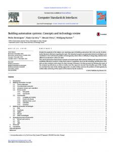
of both communication participants are verified. The session base key and the session key are only valid during a single session. They thus become invalid after the connection has been closed (e.g., timeout, disconnect message). The protocol employed is based on an improved variant of the Needham-Schroeder protocol (used in Kerberos). This variant overcomes the vulnerability of the original protocol to malicious reuse of old keys [20]. It is, however, not immediately applicable to KNX/EIB, since the length of a standard KNX/EIB message is limited to 23 octets. Without further modification of the protocol, some messages would have to be split into several messages, causing unacceptable overhead. The key server, for example, would have to send 6 messages to transmit the generated key and the ticket to the initiator. Therefore, EIBsec takes an improved approach (cf. Fig. 5). Suppose, for example, an entity A wants to set up a secure connection to B. A thus sends an A SessionKey Request message to the corresponding ACU S. This message contains the address of B and the nonces N1 and N ∗ .5 To avoid that an attacker sends an old session base key to B, a second nonce N2 is used. To retrieve this nonce, the ACU transmits an A Init Connect Request to B which sends a nonce N2 back to the ACU using an encrypted A Init Connect Response message. After having received this message, the ACU generates a 128 bit session base key KSB AB and distributes it to both communication participants. Instead of using a ticketing scheme as in [20], the session base key is sent directly to both participants. As the length of the user part of a standard KNX/EIB message (short frame format) is limited to 14 bytes, the session base key must be split. Therefore, the lower bytes of KSB AB are transmitted using the A Key Response Low service whereas the higher bytes are sent using an A Key Response High message. To avoid interception of the key, these messages are encrypted using the ∗ ∗ dynamic node keys KA and KB . Additionally, the corresponding nonce previously sent to the ACU is also included to avoid replay attacks. After this key distribution phase, both participants can calculate the session key KS AB and the initial session counter CS AB using the equation shown in Fig. 4. Secure communication in counter mode is now possible. However, an additional authentication and connection phase is proposed to improve the robustness of the protocol. Since entity-authentication is already provided by the distribution of the session key, these steps are optional. However, they provide an explicit means to verify the mutual agreement on session establishment. They also eliminate the need for a dedicated connect message. Furthermore, these steps verify the successful key distribution. Otherwise, A could send an A Auth Connect Request message to B before B has received the session base key. To reduce the likelihood of such a situation, the 5 The nonces N ∗ and N ∗ are used to calculate the dynamic node A B ∗ and K ∗ (cf. Fig. 4). keys KA B
ACU should transmit the session base key to B first. Additionally, the transmission to A should be delayed using a fixed value (e.g., a few hundred milliseconds). To start this second phase, A sends an A Auth Connect Request message to B. This message contains a nonce N3 and is encrypted using the session base key KSB AB . B receives this nonce and generates another nonce N4 . Afterwards, B performs a conversion of N3 (for example, N3� = N3 − 1) and returns the converted nonce N3� together with the generated one N4 back to A (using A Auth Connect Reply). This conversion proves that B is capable of decrypting the message. After receiving this encrypted message, A verifies if the converted nonce N3� is correct. If N3� is valid, the identity of B has been verified. To prove the identity of A, A converts the received nonce N4 and returns it to B using an encrypted A Auth Connect Response message (using KSB AB ).
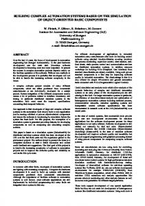
Fig. 6. First, device A must send an A Join Group Request message to its corresponding ACU which contains the group address a and the nonces N1 and NA∗ . After receiving the request, the ACU can optionally verify whether the device is actually allowed to join the group. After this step, the ACU transmits the group key together with the received nonce and the group address to A. Since the group key is 128 bits long, two response messages (A Join Group Response Low and A Join Group Response High) must be transmitted. Additionally, the ACU also transmits the current group counter value to A. This is done by sending an A Group Resync Response Low and an A Group Resync Response High message. To avoid interception of the group key and the current group counter value, these messages are encrypted using the dynamic node key ∗ KA (derived from NA∗ ). After having received the group key KG a and the current group counter value CG a , A is able to en- and decrypt group messages in counter mode.
A_SessionKey_Request
A_Join_Group_Request N 1N*A a Entity A
ACU
A_Init_Connect_Response E(K* ,N ) B
2
A_Key_Response_{Low,High} E(K*A ,KSB_AB N 1B)
E(K*B ,K SB_AB N 2 A)
A_Auth_Connect_Request
Entity B
Entity A
A_Key_Response_{Low,High}
E(K SB_AB ,N3 )
E(K SB_AB ,N’4 )
Figure 5. Session establishment in EIBsec
6.3. Secure process data communication To ensure the secure transmission of process data, group messages are encrypted in counter mode. In contrast to SEIB, it is not necessary to distribute the group keys at installation time. In EIBsec, each field device can obtain the required group key from its corresponding ACU at any time. Additionally, key revocation as well as a lifetime limitation are supported. Each communication group is assigned to one supervising ACU. This ACU randomly generates the corresponding group base key. Using the equation shown in Fig. 4, the ACU calculates the group key and the initial group counter. To perform an encryption of group messages in counter mode, a device needs the group key and the current group counter value. To join a group, it has to retrieve them from its ACU (which may have to forward the request to the group’s supervising ACU, cf. Section 7.2. The (supervising) ACU in turn must keep track of the group counter values of its assigned groups. The steps necessary to join a group G are illustrated in
E(K* ,K N a) A G_a 1 A_Group_Resync_Response_{Low, High} E(K* ,C N a) A G_a 1
Figure 6. Group key retrieval in EIBsec
A_Auth_Connect_Reply E(K SB_AB ,N’3 N 4) A_Auth_Connect_Response
A_Join_Group_Response_{Low, High} ACU
A_Init_Connect_Request A N*B
N 1 N*A B
EIBsec also allows to revoke a group key. To inform all group members about the revocation of the group key, the ACU sends an A Group Invalidate message. Afterwards, it generates a new group base key. From it, the ACU calculates the new group key and the new initial group counter value. To resume the exchange of group messages, each group member must rejoin the group using the A Join Group Request service mentioned above. This mechanism can also be used to limit the lifetime of group keys by the ACU periodically6 sending A Group Invalidate requests.
7. Key management 7.1. Node key distribution The node key distribution must be performed in a secure environment. It must be avoided that an unauthorized user intercepts or modifies a node key during distribution. Additionally, it must be prevented that an attacker uses the “key upload” mechanism to set a new key. As a key is 128 bits long and a standard KNX/EIB message can only contain 14 bytes of user data, EIBsec provides two primitives to upload a node key. A Set SecretKey Low can be used to upload the low-order 8 bytes of the key whereas A Set SecretKey High is used to send the high-order 8 bytes. To verify whether 6 As
a first approach a lifetime of 1 day seems appropriate.
the remote user is allowed to change the node key, these messages must include a 6 byte password.7 This explained mechanism has one drawback. The messages mentioned above are transmitted in clear. Thus, a malicious user could simply intercept the key or the password. Therefore, EIBsec provides additional protection mechanisms. Depending on the required security level, it is possible to choose one of the following three different modes separately for each field device: • Bus mode: The KNX/EIB bus medium can be used to upload the key. Due to security reasons, the node key distribution process must be performed in a secure environment. Therefore, this mode should only be chosen if it can be guaranteed that unauthorized users are not able to access the bus medium during node key distribution. One possible solution is to set up a minimal network containing only the device and the management station. Additionally, physical access to the particular device can also be required (e.g., pressing a button). • Local mode: In this mode, the KNX/EIB bus medium cannot be used to upload a key. Instead, the key upload is performed via a point-to-point connection. To establish such a direct connection, the standard local configuration interface for KNX/EIB components must be used. Obviously, this mode is only applicable if the device provides this interface. The main benefit of this mode is that the node key is never transmitted over the KNX/EIB network. Thus, an eavesdropper is not able to intercept the key. • Direct mode: The direct mode provides the strongest but least flexible form of security. In direct mode, neither the KNX/EIB bus nor the local configuration interface can be used to upload a node key. Thus, low level hardware access is necessary to perform a key upload. One possibility is to upload the key directly into the EEPROM of the microcontroller. The device manufacturer has to provide appropriate tools. 7.2. Forwarding keys There are two situations where a key retrieval request cannot be immediately satisfied by an ACU. First, it is possible that two communication participants from different network segments want to establish a session. In this case, the ACU contacted by the initiator does not hold the node key of the second communication partner. Thus, it cannot perform the key distribution phase of the session establishment protocol (node key miss). Second, since exactly one ACU is responsible for managing a communication group, it is possible that a device wants to join a group the ACU is not responsible for. In such a case the ACU does not have the group key and the current group counter value of the desired group and has to obtain them from the ACU supervising the group (group miss). 7 To change this password, the user must send an A Set Password message.
To resolve these situations, the ACU consults its parent ACU or one of its child ACUs. To communicate with them in a secure manner, each ACU holds the node keys of these ACUs. Fig. 7 illustrates a possible resolution of a node key miss. Suppose that entity A (address 1.1.1) wants to establish a session with entity B (address 1.2.2). To initiate a session, A sends a request to the corresponding ACU S1.1.0 (message 1). Since B is located in a different network segment, S1.1.0 does not have the node key of B. Thus, S1.1.0 is not able to distribute the generated session base key to B. By comparing the address of B and its own position in the hierarchy, S1.1.0 determines that it has to ask its parent ACU (S1.0.0 ) for the node key of B using an A PrivateKey Request message (message 2). S1.0.0 receives the request and verifies whether it has the requested key. As B is not located in the Main Line 1 but in a subordinate line, S1.0.0 sends another A PrivateKey Request message to its child ACU S1.2.0 (message 3). S1.2.0 finally possesses the requested key and sends it back to S1.0.0 using an A Key Response Low and an A Key Response High message (message 4). S1.0.0 receives the key and transmits it to S1.1.0 (message 5). After having received the node key of B, S1.1.0 is able to distribute the generated session base key to B (message 6) and to A (message 7). Afterwards, A can set up a secure channel to B using the second phase of the authentication protocol described in Section 6.2 (message 8). ACU 1.0.0
Main Line 1 2) 5)
ACU 1.1.0 1) 1.1.1 Line 1.1
7)
4)
3) ACU 1.2.0
6) 8)
1.2.2 Line 1.2
Figure 7. Key forwarding in EIBsec The resolution of a group miss is similar to that of a node key miss. If the ACU is not itself responsible for the desired group, it has to forward the request to its parent or one of its child ACUs. Since the distribution of the groups is specified at configuration time, the selection of the appropriate ACU is static and therefore can be realized using a lookup table. Compared to the example above, the A GroupKey Request service is used instead. If the receiving ACU is responsible for the group, it sends the group key and the current group counter value back to the requesting ACU. Otherwise, it forwards the request.
8. Implementation of EIBsec 8.1. Protocol implementation Compatibility is an important feature of EIBsec. Thus, the frame format of EIBsec was designed to be backward compatible with the standard KNX/EIB protocol. Fig. 8 shows the frame format. Only the transport and application layer PDU (protocol data unit) is encrypted using
AES. Since the control information for the lower layers is left in the standard cleartext format, standard KNX/EIB devices not supporting EIBsec are still able to route these frames.
A_Init_Connect_Request A_Init_Connect_Response A_Auth_Connect_Request
7
...
17
App. Data App. Data
18
...
22 Checksum
6
ACF
5
TCF
4
ACF
3
Hop Count + Length
2
Destination Address
1
Source Address
Control Field
0
*)
AES encrypted
CRC Signature
unencrypted
11 0000001 11 0000010 11 0000011
*) unencrypted
Figure 8. EIBsec frame format In Fig. 9, a detailed description of the particular EIBsec PDUs is given. Octets 0 to 5 (data link and network layer control fields) as well as the last octet (layer 2 checksum) are not shown since their format follows the KNX/EIB standard. Some EIBsec commands do not need to be encrypted (shown with white background), but most of them are encrypted using AES (gray background). Since AES has a fixed block size of 128 bits, an encrypted frame always has to contain 14 octets application data. Together with the transport and application control field, this results in 16 encrypted octets and a constant total length of 23 octets for an EIBsec frame. As mentioned earlier, KNX/EIB devices are managed via the standard tool software ETS. The integration of EIBsec management procedures into this software is not yet feasible due to the invasiveness of the necessary changes and since the ETS code base is not open. Therefore, a separate add-on tool for configuration and management of EIBsec devices is under development. A special focus is placed on automated key management (secure initial key distribution, key lifetime limitation, . . . ) with selectable parameters. 8.2. Hardware implementation The encryption of process and management data obviously takes additional resources of the communication partners (i.e., ACUs and secure field devices). Since standard KNX/EIB components do not provide the required processing power and memory, suitable hardware has to be designed. Recently, we developed a versatile embedded KNX/EIB platform [21, 22], which fulfills the hardware requirements of an ACU. Besides two KNX/EIB twisted pair (TP) interfaces, it provides EIA-232, USB and Ethernet connectivity. The platform is based on a Fujitsu MB90330F series microcontroller running at 24 MHz and also has a SD/MMC card interface for virtually unlimited storage expansion. It is shown in Fig. 10. To confirm that the performance of this platform is sufficient to handle the cryptographic algorithms on an ACU, a freely available AES implementation ([23]) was ported
A_Init_Connect_Request 6 7 8 9 10 ... 13 TCF ACF Participant Nonce A_Init_Connect_Response 6 7 8 ... 11 TCF ACF Nonce
12
... 0
17
18 ... 21 CRC signature
A_SessionKey_Request / A_PrivateKey_Request 6 7 8 ... 11 12 ... 15 16 17 Address TCF ACF Nonce Nonce A_Key_Response_{Low,High} 6 7 8 ... 15 16 17 Address TCF ACF Key {Low, High}
18
A_Auth_Connect_Request 6 7 8 ... 11 Nonce TCF ACF
12
17
A_Auth_Connect_Reply 6 7 8 ... 11 Nonce -1 TCF ACF
12
A_Auth_Connect_Response 6 7 8 ... 11 12 Nonce -1 TCF ACF
... 0
... 15 Nonce ... 0
17
... 21 Nonce 18 ... 21 CRC signature 16
17 0
18 ... 21 CRC signature
18 ... 21 CRC signature
A_Join_Group_Request / A_Group_Key_Request 6 7 8 ... 11 12 ... 15 16 17 Group TCF ACF Nonce Nonce A_Join_Group_Response_{Low,High} 6 7 8 ... 15 16 17 Group TCF ACF Key {Low, High} A_Group_Resync_Request 6 7 8 ... 11 TCF ACF Nonce
12
18
... 21 Nonce
... 15 Nonce
16 17 Group
A_Group_Resync_Response_{Low,High} 6 7 8 ... 15 16 17 18 ... 21 Group Nonce TCF ACF Cnt {Low,High} A_Group_Invalidate 6 7 8 9 Group TCF ACF
10
... 0
17
18 ... 21 CRC signature
A_Set_SecretKey_{Low,High} 6 7 8 ... 15 16 ... 21 TCF ACF Key {Low,High} Password A_Set_Password 6 7 8 ... 15 TCF ACF New Password
16 ... 21 Old Password
Figure 9. EIBsec transport and application layer PDUs
to our prototype (without further optimization). A first performance analysis shows that the encryption of a single EIBsec message takes approximately 0.59 ms net processor time. Since the total transmission time of an EIBsec message is 39 ms8 the additional processing time clearly is not a limiting factor. Our prototype thus can be expected to be able to handle encrypted messages at the maximum theoretical data rate of the KNX/EIB network. As an EIBsec-capable successor to standard KNX/EIB bus attachment units, a design based on [16] is currently under development. The goal is a small-sized device based on the low-cost TI MSP430 series. This microcontroller promises enough performance to handle the cryptographic algorithms, yet has low power consumption. The connection to KNX/EIB is realized using a TP-UART chip. As additional extensions, the standard configuration interface as well as an additional proprietary local interface will be integrated. 8 This covers the whole transmission cycle including immediate acknowledgment and required bus idle times.
Figure 10. KNXcalibur
9. Conclusion and future work EIBsec extends KNX/EIB by mechanisms for secure communication over the network. Both point-to-point and group communication are protected, including authentication of all communication partners. EIBsec is based on cryptographic algorithms and protocols which are commonly accepted as being safe. Nevertheless the presented protocol benefits from further formal validation. Its design takes the performance limitations of both network and nodes into account. A prototype implementation is currently underway. It will also be used to conduct first performance tests. Since key functionality is concentrated in the ACUs – not even devices located in the same segment can communicate securely without them – devising an appropriate redundancy scheme will be one of the next steps. Another goal is to refine the mechanisms for distribution of the node keys. With secure management communication, EIBsec already provides the basis for a mechanism for the distribution of system software updates. Still, further work is necessary to create a scheme that properly addresses the variations introduced by different node hardware platforms. Further steps include the integration of intrusion detection mechanisms as well as detection and handling of denial-of-service attacks, including the automated isolation of segments under attack. Since automation solutions based on radio communication, including the KNX/EIB compatible KNX RF, rapidly rise in popularity, research regarding their security appears as another important topic. Acknowledgements The authors are grateful to the anonymous reviewers for their comments that both enhanced this paper and contributed valuable ideas.
References [1] W. Kastner, G. Neugschwandtner, S. Soucek, and H. M. Newman, “Communication Systems for Building Automation and Control”, Proceedings of the IEEE, vol. 93, no. 6, pp. 1178–1203, 2005.
[2] “Building Automation and Control Systems (BACS) – Part 2: Hardware”, IS0 16484-2, 2004. [3] P. Neumann, “Virtual Automation Network - Reality or Dream”, in IEEE International Conference on Industrial Technology, volume 2, 2003, pp. 994– 999. [4] “Control Network Protocol Specification”, ANSI/EIA/CEA 709.1, 1999. [5] D. Loy, D. Dietrich, and H. Schweinzer, Open Control Networks, Kluwer Academic Publishers, 2002. [6] “BACnet – A Data Communication Protocol for Building Automation and Control Networks”, ANSI/ASHRAE 135, 2004. [7] “Building Automation and Control Systems (BACS) – Part 5: Data Communication Protocol”, ISO 16484-5, 2003. [8] “KNX Specification”, Version 1.1, 2004. [9] W. Kastner and G. Neugschwandtner, “EIB: European Installation Bus”, in The Industrial Communication Technology Handbook, volume 1, chapter 34. CRC Press, 2005. [10] C. Schwaiger and A. Treytl, “Smart Card Based Security for Fieldbus Systems”, in Proc. IEEE Conference on Emerging Technologies and Factory Automation (WFCS), volume 1, 2003, pp. 398–406. [11] A. D. Wood and J. A. Stankovic, “Denial of Service in Sensor Networks”, IEEE Computer, vol. 35, no. 10, pp. 54–62, 2002. [12] D. G. Holmberg, “BACnet Wide Area Network Security Threat Assessment”, Technical report, National Institute of Standards and Technology, 2003. [13] J. Zachary, R. Brooks, and D. Thompson, “Secure Integration of Building Networks into the Global Internet”, Technical report, National Institute of Standards and Technology, 2002. [14] Electronic Frontier Foundation, Cracking DES: Secrets of Encryption Research, Wiretap Politics and Chip Design, O’Reilly & Associates, 1998. [15] W. Granzer, “Security in Networked Building Automation Systems”, Master’s thesis, Vienna University of Technology, Institute of Computer Aided Automation, 2005. [16] G. Westermeir, Diversit¨are Zugangs- und Sicherheitsmechanismen angewendet in automatisierten Geb¨auden, PhD thesis, TU Munich, 2004. [17] A. Perrig, R. Szewczyk, J. D. Tygar, V. Wen, and D. E. Culler, “SPINS: Security Protocols for Sensor Networks”, in Proc. 7th Annual Intl. Conf. on Mobile Computing and Networking (MobiCom), 2001, pp. 189–199. [18] N. Okabe, S. Sakane, K. Miyazawa, K. Kamada, A. Inoue, and M. Ishiyama, “Security Architecture for Control Networks using IPsec and KINK”, in Proc. Symposium on Applications and the Internet (SAINT), 2005, pp. 414–420. [19] “Advanced Encryption Standard (AES)”, FIPS PUB 197, National Institute of Standards and Technology, 2001. [20] A. S. Tanenbaum and M. van Steen, Distributed Systems: Principles and Paradigms, Prentice Hall, 2002. [21] F. Praus, W. Kastner, and O. Alt, “Yet Another All-purpose EIBNet/IP Gateway”, in Proc. Konnex Scientific Conference, 2004. [22] F. Praus, “A versatile networked embedded platform for KNX/EIB”, Master’s thesis, Vienna University of Technology, Institute of Computer Aided Automation, 2005. [23] V. Rijmen, A. Bosselaers, and P. Barreto, “Optimised ANSI C code for the Rijndael cipher (now AES)”, http://www.iaik.tu-graz.ac.at/research/krypto/AES/, 2000, version 3.0.